1
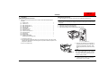
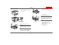
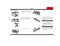
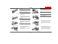
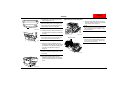
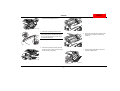
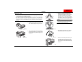
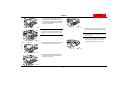
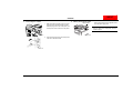
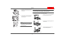
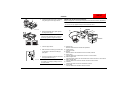
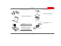
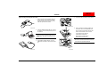
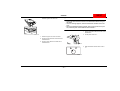
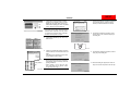
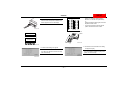
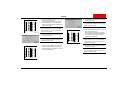
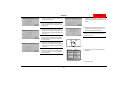
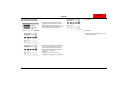
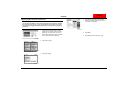
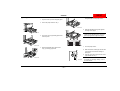
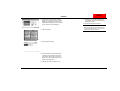
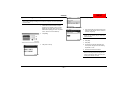
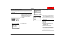
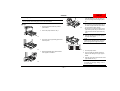
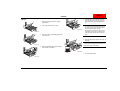
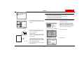
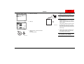
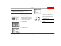
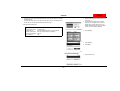
NEXT
SETUP INSTRUCTIONS
CF2001P
Printer
WARNING
• Do not plug in the power cord or turn on this unit until you are instructed to according to this manual.
CAUTION
• Install this machine so that it can quickly be unplugged from the electrical outlet in case of an
emergency. The socket-outlet shall be installed near the machine and shall be easily accessible.
• Keep all packing materials out of the reach of children.
NOTE
• If the CF2001P is connected to the Minolta MircroPress Cluster Printing System, be sure
to take back the User Manual for the CF2001P, since it is not needed by the customer.
• Keep all packing materials in a safe place for later use in case they are needed for transportation.
4004-7715-01
© MINOLTA CO., LTD.
Printed in Japan
NEXT
CF2001P
1. Outline of the CF2001P System Setup
When setting up the system consisting of this unit and its options, set up each unit in the
order shown below.
NOTE
• Install and setup each option according to the instructions included with the
option.
• For information on adjusting each option, refer to the section “10. Adjusting
the Options” on page 29.
NOTE
Set up each unit correctly according to its SETUP INSTRUCTIONS.
1-A. Copy Table CT-2
2-A. Paper Feed Unit PF-118
2-B. Large Capacity Cabinet
PF-117
3-A. Dehumidifying Heater
PF-117
2-C. Copy Desk CD-2M
3-B. Dehumidifying Heater
PF-118
4. CF2001P Printer
7. Mechanical Counter
5. Duplex Unit AD-14
8. I/F Kit
6. Data Terminal
DT-105*1,*2
9. Controller
*1: U.S.A and Canada only
*2: Not available if the MicroPress PrintLink 2020m is installed
10-A. 10-Mailbin Sorter
JS-1002*2
10-B. Finisher FN-107
10-C. Finisher FN-108*2
C4004U551CA
4004-7715-01
–1–
NEXT
CF2001P
2. Unpacking
■ Unpacking the Printer
1. Open the printer box, and then remove the box containing the imaging unit.
■ Unpacking the Accessories
1. Remove the accessories from the box, and then check that the following are
enclosed.
(1)
(2)
(3)
(4)
(5)
(6)
(7)
(8)
(9)
(10)
(11)
(12)
(13)
Imaging units . . . . . . . . . . . . . . . . . . . . . . . . . . . . . . . . . . . . . . . . . . . . . . .
Power cord *1 . . . . . . . . . . . . . . . . . . . . . . . . . . . . . . . . . . . . . . . . . . . . . .
LED cleaning tool *2 . . . . . . . . . . . . . . . . . . . . . . . . . . . . . . . . . . . . . . . . .
LED cleaning paper *2 . . . . . . . . . . . . . . . . . . . . . . . . . . . . . . . . . . . . . . .
Manual holder . . . . . . . . . . . . . . . . . . . . . . . . . . . . . . . . . . . . . . . . . . . . . .
User Manual . . . . . . . . . . . . . . . . . . . . . . . . . . . . . . . . . . . . . . . . . . . . . . .
Setup Instructions . . . . . . . . . . . . . . . . . . . . . . . . . . . . . . . . . . . . . . . . . . .
Warranty card *3 . . . . . . . . . . . . . . . . . . . . . . . . . . . . . . . . . . . . . . . . . . . .
Power cord instruction *1. . . . . . . . . . . . . . . . . . . . . . . . . . . . . . . . . . . . . .
Paper size label . . . . . . . . . . . . . . . . . . . . . . . . . . . . . . . . . . . . . . . . . . . . .
Cable clamp . . . . . . . . . . . . . . . . . . . . . . . . . . . . . . . . . . . . . . . . . . . . . . .
Support label . . . . . . . . . . . . . . . . . . . . . . . . . . . . . . . . . . . . . . . . . . . . . . .
Additional information
(Storing the LED cleaning tool) . . . . . . . . . . . . . . . . . . . . . . . . . . . . . . . . .
NOTE
Remove the box containing the imaging unit before removing the box from around
the printer.
4
1
1
1
1
1
1
1
1
1
1
1
2.
3.
4.
Remove the box from around the printer.
Remove the printer from the plastic bag.
Open the two handle covers, and then pull out the handles.
1
*1 For Particular area only.
*2 The LED cleaning tool and its paper are not used during setup. Since they will be
needed when the imaging unit is changed or the printer is cleaned, keep them in a
safe place for later use.
*3 U.S.A. and Canada only.
C4004U003AA
5. Grasp the two handles on the right side of
the printer and the two grips on the left (as
shown in the illustration), and then, while
keeping the printer level, remove it from its
box.
C4004U004AA
NOTE
The printer weighs about 77 kg (169-3/4
lbs.). The printer must be lifted by at least
two people. When lifting the printer, be careful not to strain your back.
6. Carefully place the printer on a level and
sturdy surface, such as a table.
4004-7715-01
–2–
NEXT
CF2001P
■ Removing the Protective Tape and Packing Materials
<Outside Surface of the Printer>
3. Remove the 2 pieces of packing material
from the paper-lifting plate.
Remove the tape affixed to the outside surface of the printer.
C4004U145AA
4. Close the paper drawer.
C4004U005AA
5. Pull out the paper drawer for Tray 2.
Paper take-up
roller
Packing
material
Tapes
<Paper Feed Section>
Paper take-up
roller
7. Remove the packing material from the
paper-lifting plate.
1. Pull out the paper drawer for Tray 1.
8
NOTE
Be careful not to touch the surface of the
paper take-up roller with your hands. If the
roller has been touched, wipe it with a dry
cloth.
C4004U024AA
2. Remove the 2 pieces of tape shown in the
illustration from the paper-lifting plate.
4004-7715-01
C4004U026AB
6. Remove the 3 pieces of tape affixed to the
paper-lifting plate as shown.
C4004U006AA
Packing
material
NOTE
Be careful not to touch the surface of the
paper take-up roller with your hands. If the
roller has been touched, wipe it with a dry
cloth.
–3–
Close the paper drawer.
NEXT
CF2001P
3. Installing the Units
4. Remove the packing material from the imaging unit slot.
■ Installing the Imaging Units
1. Grasp the handle of the front door, and then
carefully swing the door open to the right as
shown.
C4004U144AA
C4004U011AA
2. Pinch the release lever for the yellow imaging unit. (The colors of the imaging units are,
from the left, yellow, magenta, cyan, and
black.)
Protective tape
C4004U049AB
NOTE
• The imaging unit can easily be damaged
by light. Therefore, leave the imaging unit
in its protective plastic bag until immediately before it is to be installed.
• After removing the imaging unit from its
protective plastic bag, make sure that it is
not exposed to light, and immediately
install it into the printer.
6. Hold the imaging unit in both hands, tilt it to
the left, and then lightly shake it twice in the
direction of the tilt. Next, hold the unit tilted to
the right, and then lightly shake it twice in the
direction of the tilt.
C4004U047AA
3. Swing the release lever toward you.
C4660U001AB
C4004U048AA
4004-7715-01
5. Remove the yellow imaging unit from its box
and its protective plastic bag, and then place
the imaging unit on a stable, level surface,
such as a table.
–4–
NEXT
CF2001P
7. Remove the protective tape from the imaging unit.
Protective sheet
NOTE
Be sure to insert the imaging unit until the
end of the bottom imaging unit cover contacts the back of the imaging unit compartment.
NOTE
The clear plastic protective sheet is not
packing material; therefore, do not remove
it.
*
C4004U193AA
*
The additional protective sheet, indicated by
the shaded area, is only attached to the
black imaging unit.
C4004U052AB
NOTE
Do not insert the imaging unit into the compartment at an angle.
8. Keeping the imaging unit level, pick it up by
supporting it on the bottom with your left
hand and on the bottom at the front with your
right hand.
C4004U215AB
NOTE
When holding the imaging unit, be sure to
hold it by its bottom cover. If the top imaging
unit cover is held, it may fall off or the PC
drum installed on the imaging unit may
become damaged, resulting in decreased
image quality.
C4004U217AB
10. While keeping the bottom of the imaging unit
supported with your left hand, carefully
insert the imaging unit with your right hand,
as shown, until the cartridge snaps into
place.
C4004U216AB
C4004U053AB
9. Keeping the imaging unit level, insert the
imaging unit as far as possible into the imaging unit compartment.
Insert the imaging unit with the protective
sheet(s) attached.
C4004U051AC
4004-7715-01
11. Pull out the empty imaging unit cover.
The empty imaging unit cover for the black
imaging unit can simply be pulled out, even if
the protective sheets on the imaging unit
become caught on the toner hopper lid.
C4004U054AB
–5–
NEXT
CF2001P
■ Installing the Oil-Coating Unit
12. Separate the top and bottom halves of the
empty imaging unit cover.
1. Grasp the upper right-side door as shown,
and then carefully open the door completely
while making sure to support it.
NOTE
Since the bottom half of the imaging unit
cover will be used when the imaging unit is
replaced again, store it in a safe place.
NOTE
Be sure to support the upper right-side door
while carefully opening it; otherwise, it may
become damaged.
Bottom cover
C4004U055AA
13. Carefully swing the release lever back up to
its original position, pushing it in until it locks
into place.
C4004U173AA
NOTE
If the release levers are not correctly positioned, the front door cannot be closed.
Metal terminals
NOTE
Do not touch the metal terminals at the front
of the fusing unit; otherwise, damage may
occur due to static electricity.
C4004U056AA
14. Remove the packing materials from the
remaining imaging unit slots, and then install
the magenta, cyan, and black imaging units
in the same way described in steps 2
through 13.
NOTE
Be sure to install the imaging units in their
correct slots.
C4004U149AB
15. After all four imaging units have been
installed, grasp the handle of the front door,
and then carefully swing the door closed as
shown.
C4004U013AA
4004-7715-01
–6–
NEXT
CF2001P
5. Swing the oil-coating unit up to install it.
2. Remove the two pieces of tape from the lock
levers of the oil-coating unit shown.
C4004U150AB
C4004O153AA
3. Remove the oil-coating unit from its box.
6. Secure the oil-coating unit by moving the two
lock levers (one on each end of the unit)
toward you.
NOTE
When picking up the oil-coating unit, pick it
up by the two handles (one on each end of
the unit) with both hands.
C4004U151AA
C4004O154AA
4. Insert the oil-coating unit, making sure that
the two pins (one on each end of the unit) fit
into the notches in the printer.
7. Grasp the upper right-side door as shown,
and then carefully close it.
C4004U152AB
C4004U174AA
4004-7715-01
–7–
NEXT
CF2001P
■ Filling the Toner
3. Remove the yellow toner bottle from its
packaging. Hit the bottom of the bottle
against a strong surface, such as a desk or
table, four or five times from a height of
about 10 cm (4 in.). (Since the toner within
the bottle may have become compacted, be
sure to break it up by performing this step.)
NOTE
• The toner bottles are not included. A bottle of toner is needed for each color (four
in total) and should be purchased separately.
• Be careful not to spill toner inside the printer or get toner on your clothes and
hands. If toner gets on your hands, wash them using water and a neutral soap. If
toner gets in your eyes, immediately rinse them, and then consult a medical professional.
NOTE
Be sure to hit the bottom of the toner bottle
against the strong surface (the opening of
the bottle should be pointing up).
1. Grasp the toner hopper door as shown, and
then carefully swing the door up to open it.
C4004U010AA
C4004U058AA
4. While holding the bottle securely, shake it
well in all directions to mix up the toner.
2. Open the yellow toner hopper lid (leftmost)
by swinging it toward you. (The toner hopper
lids are, from the left, yellow, magenta, cyan,
and black.)
C4004U060AA
C4004U059AA
5. With the rounded side (marked with “▼”) of
the bottle mouth facing towards you, place
the toner bottle on top of the hopper, and
then press down on the bottle until it snaps
into place.
C4004U061AA
4004-7715-01
–8–
NEXT
CF2001P
9. Carefully close the yellow toner hopper lid.
6. Fully pull the toner hopper shutter out toward
you. Pulling out the toner hopper shutter
allows the toner to begin filling the toner hopper. Check that all of the toner has emptied
out of the toner bottle and into the hopper,
which may take a while.
C4004U066AA
C4004U062AA
10. Fill the magenta, cyan, and black toner in the
same way (as described in steps 2 through
9).
NOTE
Do not tap on the toner bottle while refilling
the hopper; otherwise, the toner may spurt
out.
NOTE
Be sure to fill the toner hoppers with the correct color of toner.
11. After all four toner hoppers are filled, grasp
the toner supply door as shown, and then
carefully swing the door down to close it.
C4004U063AA
7. Push the toner hopper shutter closed until it
snaps into place and closes the bottle.
C4004U067AA
C4004U064AA
8. Tilt the toner bottle slightly backward, and
then pull the opening of the bottle up and
toward you to remove it.
C4004U065AB
4004-7715-01
–9–
NEXT
CF2001P
4. Connecting the Cables
5. Affixing the Support Label
1. Make sure that the printer power cord is not
plugged into the electrical outlet, and then
insert the plug on the end of the power cord
into the power cord connector on the printer.
C4005U552AA
C4004U139CA
– 10 –
Affix the support label on the right side of the
top of the toner supply door.
NOTE
Affix the label that corresponds with the
installed options.
C4004U589AA
2. Insert the plug on the other end of the power
cord into an electrical outlet.
4004-7715-01
Support label
NEXT
CF2001P
6. Installing the Manual Holder
7. Checking the Operation of the Printer
1. Insert the tab on the bottom of the manual
holder into the slot in the printer as shown in
the illustration.
NOTE
Before adjusting the printer, be sure to install the interface kit and the controller. For more details on their installation, refer to their manuals.
■ Loading Test Paper
Load test paper specifically for use with X-Rite calibration.
1. Prepare A4-size (or Letter-size) plain paper.
C4004U553AA
2. Insert the tabs on the left and right sides of
the manual holder into the corresponding
slots in the printer.
2. Pull out the paper drawer for Tray 1.
C4004U071AA
C4004U554AA
3. Press down on the paper-lifting plate until it
locks into place.
NOTE
If the optional finisher is used, attach the
manual holder to the back of the finisher at
the position shown, using the same procedure described above.
C4004U072AA
C4004U098AA
4. Slide the adjustable paper guides to the
A4(C) (or Letter(C)) paper size.
C4004U073AA
4004-7715-01
– 11 –
NEXT
CF2001P
5. Load the prepared A4(C)-size (or Letter(C)size) plain paper into the paper drawer.
■ Setting Up the Servicing Equipment
Set up the equipment in order to print a test pattern and make the necessary adjustments.
NOTE
Do not turn on any equipment until you are instructed to do so.
(4)
C4004U074AA
(2)
(5)
6. Slide the adjustable paper guides against
the edges of the paper.
(8)
(3)
NOTE
Check that the adjustable paper guides are
pushed up against the edges of the paper.
(6)
(7)
CF2001P
(1)
C4004U170AA
7. Close the paper drawer.
8. Make sure that the media type selection dial
on the drawer is turned to the setting for
plain paper.
9. From the control panel, select the size of the
test paper loaded into Tray 1.
C4004U075CA
4004-7715-01
NOTE
For details on specifying settings, refer to
the User Manual.
(1) Notebook PC
Starts the External Panel Controller for adjustment.
(2) X-Rite (DTP32)
Color Tone Tester
(3) Selector
Switches between the Notebook PC and the X-Rite, CF2001P
(4) DTP32 cable
Connects between the X-Rite and the connector A of the selector
(5) RS232 straight cable
Connects between COM1 port of the Notebook PC and the connector C of the selector
(6) RS232 straight cable
Connects between the converter and the connector B of the selector
(7) Converter
Converts the RS422 connector to the RS232 connector
(8) IR Port cable
Connects between the CF2001P and the converter
– 12 –
NEXT
CF2001P
■ Setting Up the Converter (7)
■ Setting Up the Selector (3)
1. Remove the converter from its box.
1. Remove the selector from its box.
C4004U601AA
2. Remove the two screws from the selector,
and then remove the upper cover.
C4004U556AA
2. Remove the screw at the bottom of the converter, and then remove the upper cover.
C4004U602AA
C4004U557AA
3. Affix aluminum tape to the converter as
shown in the illustration.
3. Set the TERM switch (S2) to ON as shown in
the illustration.
TERM
O
N
1
S2
NOTE
• Set the button on the converter to “Normal”.
• In order to reduce the risk of damage to
the circuit board due to static electricity,
do not touch the circuit board pattern.
• Do not change the setting of any
switches other than those specified.
C4004U558AA
4004-7715-01
– 13 –
Aluminum tape
C4004U603AA
NEXT
CF2001P
■ Connecting the Equipment Cables
4. Connect the IR port cable (8) to the printer.
1. Insert a connector on the DTP32 cable (4)
into the I/O port on the side of the X-Rite,
and then insert the other connector of the
cable into port B on the selector.
C4004U562AA
C4004U559AA
5. Using a common screwdriver, tighten the
four screws shown in the illustration, and
then connect the harnesses of the IR port
cable to the terminals on the converter.
2. Using the RS232 straight cable (5), connect
the COM 1 port of the computer to port C on
the selector.
TXA terminal: brown harness
TXB terminal: red harness
RXA terminal: orange harness
RXB terminal: blue harness
NOTE
Make sure that the RS232 straight cable is
connected to the COM 1 port of the computer.
C4004U560AA
NOTE
Be sure to connect the harnesses of the IR
port cable to the specified terminals.
3. Using RS232 straight cable (6), connect
DB25 of the converter to port A of the selector.
Brown
Blue
Orange
C4004U563AA
C4004U561AA
4004-7715-01
Red
– 14 –
NEXT
CF2001P
6. Loosen the screw of the terminal, and then
attach the ground wire as shown.
■ X-Rite Caliblation
NOTE
• Start up the External Panel Controller on the Notebook PC before turning on
the printer.
• If an error message appears, follow the instructions described in the message.
• Do not quit the External Panel Controller while it is being used. If it is quitted, restart the printer and the External Panel Controller.
1. Start up the External Panel Controller on the
Notebook PC.
2. Set the power switch to “I”.
C4004U604AA
7. Attach the upper cover of the converter.
8. Plug the power cable of the converter into an
electrical outlet.
9. Plug the power cable of the X-Rite into an
electrical outlet.
C4004U564AA
3. Make sure that the selector knob is set to
“A”.
C4004U598AA
4004-7715-01
– 15 –
NEXT
CF2001P
4. Check that the External Panel Controller
appears in the computer screen, and then
display the Tech. Rep. Mode screen. (For
details about displaying the Tech. Rep. Mode
screen, refer to the Service Manual.)
C4004P565CA
NOTE
If the basic screen does not appear in the
External Panel Controller, turn the printer
off. Restart the External Panel Controller,
and then turn the printer on again.
7. After the test patterns are printed, check that
the message appears, and then click the
Start key in the External Panel Controller.
C4004P569CA
8. Check that the dialog box appears, set the
selector knob to “B”, and then click [OK] in
the dialog box.
5. Click [X-Rite Calibration] in the Tech. Rep.
Mode screen.
C4004P570CA
C4004P597CA
C4004U571AA
6. Check the message that appears, and then
click the Start key in the External Panel Controller.
Test patterns are printed for the four colors.
(Cyan, Magenta, Yellow, Black)
C4004P567CA
Test patterns
NOTE
• Since it may take some time to output the
test patterns (about 2 minutes), wait until
printing is finished.
• During printing, do not open the front
door. If the front door is opened, restart
the procedure from step 1.
9. Check that the dialog box appears, and then
click [Yes] in the dialog box.
C4004P572CA
10. When the dialog box appears, the auto-cal
strip can be read. Prepare the auto-cal strip.
C4004U568AA
C4004P573CA
4004-7715-01
– 16 –
NEXT
CF2001P
11. Insert the auto-cal strip into the X-Rite.
NOTE
Insert the auto-cal strip after “INSERT CAL
STRIP” appears on the X-Rite display.
13. Prepare the cyan test pattern, set the X-Rite
guide to “10”, and then feed the pattern in
direction “1” to read the row represented by
“A”.
Align the test pattern with the guide, and insert
the pattern into the X-Rite.
1
3
*
B
C4004U574AA
2
D
4
C
The arrows indicate the direction that the
pattern should be fed into the X-Rite.
A
C4004U576AA
Guide
Reading . . .
0.08
0.08
0.06
CALIBRATION OK
MANU
C4004U577AA
C4004U594CA
14. Check that the area indicated in the dialog
box appears in [OK].
12. Check that the dialog box appears.
NOTE
The dialog box appears if the auto-cal strip
was read correctly.
NOTE
The area indicated appears in [OK] if the
pattern was read correctly.
C4004P578CA
C4004P575CA
4004-7715-01
– 17 –
NEXT
CF2001P
1
3
B
D
2
C
4
18. Check that the area indicated in the dialog
box appears in [OK].
15. Feed the test pattern in direction “2” to read
the row represented by “B”.
When feeding the test pattern to read the
row represented by “B”, turn the paper to
feed it in the correct direction without adjusting the X-Rite guide.
NOTE
The area indicated appears in [OK] if the
pattern was read correctly.
C4004P580CA
NOTE
When reading the row in the test pattern
represented by “B”, do not change the setting of the X-Rite guide.
A
1
3
C4004U576AA
16. Check that the area indicated in the dialog
box appears in [OK].
NOTE
The area indicated appears in [OK] if the
pattern was read correctly.
B
2
C4004P579CA
1
3
B
2
D
4
C
4
C
A
NOTE
When reading the row in the test pattern
represented by “D”, do not change the setting of the X-Rite guide.
C4004U576AA
17. Turn the cyan test pattern to its original orientation, set the X-Rite guide to “30”, and
then feed the pattern in direction “3” to read
the row represented by “C”.
A
C4004U576AA
4004-7715-01
D
19. Feed the test pattern in direction “4” to read
the row represented by “D”.
When feeding the test pattern to read the
row represented by squares, turn the paper
to feed it in the correct direction without
adjusting the X-Rite guide.
– 18 –
20. Check that the area indicated in the dialog
box appears in [OK].
NOTE
The area indicated appears in [OK] if the
pattern was read correctly.
NEXT
CF2001P
21. Check that “Read the Pattern of Cyan” disappears, and that >> appears beside “Read
the Pattern of Magenta”.
C4004P582CA
24. Prepare the black test pattern, and then
repeat steps 13 through 21 of the above procedure to read the black test pattern with the
X-Rite.
NOTE
If the cyan test pattern is read correctly,
“Read the Pattern of Cyan” disappears from
the dialog box.
C4004P592CA
25. Check that the dialog box appears, set the
selector knob on the selector from “B” to “A”,
and then click [OK] in the dialog box.
22. Prepare the magenta test pattern, and then
repeat steps 13 through 21 of the above procedure to read the magenta test pattern with
the X-Rite.
C4004P590CA
NOTE
If the magenta test pattern is read correctly,
“Read the Pattern of Magenta” disappears
from the dialog box.
23. Prepare the yellow test pattern, and then
repeat steps 13 through 21 of the above procedure to read the yellow test pattern with
the X-Rite.
C4004P591CA
NOTE
Be sure to click [OK] only after the selector
knob has been set.
C4004P595CA
A
B
C4004U593AA
NOTE
If the yellow test pattern is read correctly,
“Read the Pattern of Yellow” disappears
from the dialog box.
26. Check that the Tech. Rep. Mode screen is
displayed.
C4004P597CA
27. Click [Fin. Time].
4004-7715-01
– 19 –
NEXT
CF2001P
8. Making System Setting
3. Click [END].
■ Checking the Date Setting
1. Check that the External Panel Controller
appears in the computer screen, and then
display the Date/Time Input screen. (For
details about displaying the Date/Time Input
screen, refer to the Service Manual.)
C4004PU09CA
4. Click [Menu].
C4004P565CA
5. Check that the Basic screen appears on the
External Panel Controller.
C4004PU07CA
2. Check that the current date and time settings
are correct. If the settings are not correct,
use the keypad in the External Panel Controller to enter the correct date and time in
the upper row of the screen.
Example)
To specify April 1, 2001 15:30, click:
[2], [0], [0], [1], [0], [4], [0], [1], [1], [5], [3], [0]
C4004PU08CA
4004-7715-01
– 20 –
NEXT
CF2001P
■ Specifying the Serial Number
4. Make sure that [Printer] is selected. Using
the keypad in the External Panel Controller,
enter the printer’s serial number.
Repeat this step to enter the serial numbers
for [LCC], [Sorter/FN], and [Duplex].
NOTE
Be sure to specify the serial number.
When the serial number is specified, the settings for each unit can be read by the
printer. If the serial number is not specified, a correctly adjusted image cannot be
printed.
C4004P585CA
1. Check that the External Panel Controller
appears in the computer screen, and then
display the Tech. Rep. Mode screen.(For
details about displaying the Tech. Rep. Mode
screen, refer to the Service Manual.)
C4004P565CA
2. Click [System Input].
C4004P597CA
3. Click [Serial # Input].
C4004P584CA
4004-7715-01
– 21 –
5. Click [END].
6. Click [Menu], and then click [Fin. Time].
NEXT
CF2001P
■ Specifying Who Performs Replacements
4. Click [User] or [Service] to select whether
each unit should be replaced by the user or
the service representative.
NOTE
The message that appears a unit must be replaced can be changed to indicate
that either the user or the service representative must perform the replacement. Select the appropriate settings depending on the type of servicing being
performed.
C4004PU02CA
1. Check that the External Panel Controller
appears in the computer screen, and then
display the Tech. Rep. Mode screen. (For
details about displaying the Tech. Rep. Mode
screen, refer to the Service Manual.)
C4004P565CA
2. Click [System Input].
C4004P597CA
3. Click [Unit Change].
C4004P584CA
4004-7715-01
– 22 –
5. Click [END].
6. Click [Menu], and then click [Fin. Time].
NEXT
CF2001P
■ Printing the List
5. Load the prepared A4(L)-size (or Letter(L)size) plain paper into the paper drawer.
1. Prepare A4-size (or Letter-size) plain paper.
2. Pull out the paper drawer for Tray 1.
C4004U087AA
6. Slide the adjustable paper guides against
the edges of the paper.
C4004U071AA
NOTE
Check that the adjustable paper guides are
pushed up against the edges of the paper.
3. Press down on the paper-lifting plate until it
locks into place.
C4004U072AA
C4004U172AA
7. Close the paper drawer.
4. Slide the adjustable paper guides to the
A4(L) (or Letter(L)) paper size.
8. Make sure that the media type selection dial
on the drawer is turned to the setting for
plain paper.
9. From the control panel, select the size of the
paper loaded into Tray 1.
C4004U073AA
C4004U075CA
4004-7715-01
– 23 –
NOTE
For details on specifying settings, refer to
the User Manual.
NEXT
CF2001P
10. Check that the External Panel Controller
appears in the computer screen, and then
display the Tech. Rep. Mode screen. (For
details about displaying the Tech. Rep. Mode
screen, refer to the Service Manual.)
16. Exit the External Panel Controller.
NOTE
Before connecting or disconnecting the harnesses of the IR port cable, be sure to turn
off the printer and the converter.
C4004P565CA
11. Click [List Output].
C4004P597CA
12. Click [Image Processing].
C4004PU10CA
13. Click the [Start] key in the External Panel
Controller. A list of image processing settings and the values of each counter are
printed out on four sheets of A4(L)-size (or
Letter(C)-size) plain paper.
14. Click [Menu], and then click [Fin. Time].
4004-7715-01
15. Check that the message displayed in the
control panel changes from “Alert Printing
suspended” to “Info”.
– 24 –
NEXT
CF2001P
■ To set the “Energy Save Mode” parameter
4. Click [Energy Save Mode.]
NOTE
When making settings according to the customer’s requests, refer to the procedure
described below.
1. Check that the External Panel Controller
appears in the computer screen, and then
display the Tech. Rep. Mode screen. (For
details about displaying the Tech. Rep. Mode
screen, refer to the Service Manual.)
C4004P600CA
5. Using the keypad in the External Panel Controller, enter the desired number of minutes,
and then click [Enter].
2. Click [Utility].
NOTE
Select the [C] (Clear) key to erase the
entered number.
C4004P058CA
6. Click [Exit].
C4004P565CA
7. Click [Exit].
3. Click [User’s Choice].
8. Check that the message displayed in the
control panel changes from “Alert Printing
suspended” to “Info”.
9. Exit the External Panel Controller.
NOTE
Before connecting or disconnecting the harnesses of the IR port cable, be sure to turn
off the printer and the converter.
C4004P599CA
4004-7715-01
– 25 –
NEXT
CF2001P
■ To set the “Sleep Mode” parameter
4. Click [Sleep Mode.]
NOTE
When making settings according to the customer’s requests, refer to the procedure
described below.
1. Check that the External Panel Controller
appears in the computer screen, and then
display the Tech. Rep. Mode screen. (For
details about displaying the Tech. Rep. Mode
screen, refer to the Service Manual.)
C4004P600CA
5. Using the keypad in the External Panel Controller, enter the desired number of minutes,
and then click [Enter].
2. Click [Utility].
NOTE
Select the [C] (Clear) key to erase the
entered number.
C4004P059CA
6. Click [Exit].
C4004P565CA
7. Click [Exit].
3. Click [User’s Choice].
8. Check that the message displayed in the
control panel changes from “Alert Printing
suspended” to “Info”.
9. Exit the External Panel Controller.
NOTE
Before connecting or disconnecting the harnesses of the IR port cable, be sure to turn
off the printer and the converter.
C4004P599CA
4004-7715-01
– 26 –
NEXT
CF2001P
9. Loading Paper
5. Load the paper into the drawer so that the
front side of the paper (the side facing up
when the package was unwrapped) faces
up.
NOTE
For more details about loading paper, refer to the User Manual.
■ Tray 1
1. Prepare paper that meets this product’s
specifications.
C4004U074AA
2. Pull out the paper drawer for Tray 1.
NOTE
• Do not load so much paper that the top of
the stack is higher than the mark indicating the maximum paper capacity.
• Be careful not to touch the surface of the
paper take-up roller with your hands. If the
roller has been touched, wipe it with a dry
cloth.
6. Slide the adjustable paper guides against
the edges of the paper.
C4004U071AA
NOTE
Check that the adjustable paper guides are
pushed up against the edges of the paper.
3. Press down on the paper-lifting plate until it
locks into place.
C4004U170AA
C4004U072AA
7. Close the paper drawer.
4. Slide the adjustable paper guides to fit the
size of paper to be loaded.
8. Turn the media type selection dial on the
drawer to the setting for the type of paper
loaded.
9. From the control panel, select the size of the
paper loaded into Tray 1.
NOTE
For details on specifying settings, refer to
the User Manual.
C4004U073AA
4004-7715-01
– 27 –
NEXT
CF2001P
■ Tray 2
5. Load the paper into the drawer so that the
front side of the paper (the side facing up
when the package was unwrapped) faces
up.
1. Prepare paper that meets this product’s
specifications.
2. Pull out the paper drawer for Tray 2.
C4004U079AA
C4004U076AA
3. Press down on the paper-lifting plate until it
locks into place.
NOTE
• Do not load so much paper that the top of
the stack is higher than the mark indicating the maximum paper capacity.
• Be careful not to touch the surface of the
paper take-up roller with your hands. If the
roller has been touched, wipe it with a dry
cloth.
6. Slide the lateral guides against the edges of
the paper.
NOTE
Check that the lateral guides are pushed up
against the edges of the paper.
C4004U077AA
4. Slide the adjustable paper guides to fit the
size of paper to be loaded.
C4004O108AA
7. Close the paper drawer.
C4004U078AA
4004-7715-01
– 28 –
NEXT
CF2001P
8. Affix the enclosed paper size label to Tray 2
as shown.
9. Affix the enclosed drawer number label as
shown.
Paper size label
Drawer number label
C4004U141AA
10.Adjusting the Options
NOTE
• With the CF2001P, the adjustments of each option are performed with the
servicing equipment. Therefore, start up the External Panel Controller, and
make the adjustments with the appropriate setting.
• After adjusting the options, restart the printer.
■ Checking the Paper Reference Position for PF-118
NOTE
• For details on the installing PF-118, refer to its Setup Instructions.
• To adjust PF-118, follow the instructions below.
• To exit the External Panel Controller, refer to step 14 on page 24.
1. Load A4-size (or Letter-size) paper into the
paper drawer of the optional paper feed unit.
2. Check that the External Panel Controller
appears in the computer screen, and then
display the Tech. Rep. Mode screen. (For
details about displaying the Tech. Rep. Mode
screen, refer to the Service Manual.)
C4004P565CA
3. Click [Machine Adjust].
C4004P597CA
4004-7715-01
– 29 –
NEXT
CF2001P
4. Click [PRT Area].
7. Measure margin a from the edge of the
paper to the pattern printed in the test page,
and then check that the width of the measured margin meets its standard width.
a
Standard width of the margin (a):
3.0 mm ± 1.0 mm (with Fiery X3e installed)
5.0 mm ± 1.0 mm (with MicroPress PrintLink
2020m installed)
C4004P588CA
If the width of the measured margin does not
meet its standard width, follow the procedure
in the next section, “Adjusting the Paper Reference Position for PF-118”, to adjust it.
5. Click [Left Margin].
C4658U028AA
C4658P003CA
6. Select the key for the paper drawer that is to
be adjusted, and then click the Start key in
the External Panel Controller.
A test page is printed.
C4658P005CA
4004-7715-01
– 30 –
NEXT
CF2001P
■ Adjusting the Paper Reference Position for PF-118
1. Check that the External Panel Controller
appears in the computer screen, and then
display the Tech. Rep. Mode screen. (For
details about displaying the Tech. Rep. Mode
screen, refer to the Service Manual.)
C4004P565CA
5. Select the paper drawer that you wish to
adjust, and then click the up and down
arrows in the lower-right corner of the screen
to enter the difference between the measured width and the standard width.
C4658O005CA
2. Click [Machine Adjust].
6. Print a test page and check the paper reference position.
If the width of the measure margin does not
meet its standard width, follow the instructions described below.
7. Open the paper drawer for the cassette that
needs to be adjusted, and then remove all of
the paper.
8. Loosen the two screws on the guide plate at
the bottom of the paper drawer.
C4004P597CA
3. Click [PRT Area].
C4658U024AA
9. Adjust the guide plate to the appropriate
position on the scale inside the paper
drawer.
C4004P588CA
4. Click [Left Margin].
C4658U025AA
C4658P003CA
4004-7715-01
– 31 –
NEXT
CF2001P
10. Check that the message displayed in the control panel changes from “Alert Printing
suspended” to “Info”.
11. Exit the External Panel Controller.
■ Checking and Adjusting the Paper Reference Position for PF-117
NOTE
• For details on the installing PF-117, refer to its Setup Instructions.
• To adjust PF-117, follow the instructions below.
• To exit the External Panel Controller, refer to step 14 on page 24.
1. Load A4-size (or Letter-size) paper into the
paper drawer of the large-capacity cabinet.
2. Check that the External Panel Controller
appears in the computer screen, and then
display the Tech. Rep. Mode screen. (For
details about displaying the Tech. Rep. Mode
screen, refer to the Service Manual.)
C4004P565CA
3. Click [Machine Adjust].
C4004P597CA
4. Click [PRT Area].
C4004P588CA
4004-7715-01
– 32 –
NEXT
CF2001P
■ Checking and Adjusting the Paper Reference Position for AD-14
5. Click [Left Margin].
NOTE
• Perform the procedure below after adjusting the paper reference positions for the
paper feed unit and the large-capacity cabinet.
• For details on the installing AD-14, refer to its Setup Instructions.
• To adjust AD-14, follow the instructions below.
• To exit the External Panel Controller, refer to step 14 on page 24.
C4658P003CA
6. Select the key for the third paper drawer, and
then click the Start key in the External Panel
Controller.
1. Load A4-size (or Letter size) paper into the
paper drawer of the Tray1.
2. Check that the External Panel Controller
appears in the computer screen, and then
display the Tech. Rep. Mode screen. (For
details about displaying the Tech. Rep. Mode
screen, refer to the Service Manual.)
C4659P002CB
C4004P565CA
3. Click [Machine Adjust].
7. Measure the margin from the edge of the
paper to the pattern printed in the top-right
corner of the test page.
a
Standard width (a):
3.0 mm ± 1.0 mm (with Fiery X3e installed)
5.0 mm ± 1.0 mm (with MicroPress PrintLink
2020m installed)
C4004P597CA
4. Click [PRT Area].
Click the up and down arrows in the lowerright corner of the screen to enter the difference (in millimeters) between the measured
width and the standard width.
C4658U028AA
8. Print another test page and check the paper
reference position.
C4004P588CA
4004-7715-01
– 33 –
NEXT
CF2001P
5. Click [Dup. Left Margin].
8. Measure the width of loss for the test pattern
printed on the back of the test page.
NOTE
Do not measure from the back of the test
pattern.
a
Standard width (a):
3.0 mm ± 1.0 mm (with Fiery X3e installed)
5.0 mm ± 1.0 mm (with MicroPress PrintLink
2020m installed)
C4657P001CA
6. Click [1st.].
C4657U014AA
If the measured width of loss does not meet
its standard width, click
and
in the
lower-right corner of the screen to adjust the
width. Print another test page and check the
printed image.
C4659P002CA
9. Adjust the paper reference positions for the
2nd, 3rd and 4th drawers in the same way
(by repeating steps 6 through 8).
7. Click the Start key in the External Panel
Controller.
A test page is printed.
NOTE
The 4th drawer is only available if two
optional paper feed units are installed.
C4004U596CA
4004-7715-01
– 34 –
NEXT
CF2001P
■ Checking the Hole-Punching Positions for FN-107
6. Click [Hole-Punch].
NOTE
• For details on the installing FN-107, refer to its Setup Instructions.
• To adjust FN-107, follow the instructions below.
• To exit the External Panel Controller, refer to step 14 on page 24.
1. Unplug the power cord, and then turn off the
printer.
C4683P005CA
7. Click the Start key in the External Panel
Controller.
2. Load A4-size (or Letter-size) paper (in landscape orientation) into Tray 1.
8. Fold the paper that is fed out in half, and
check that the punched holes are aligned.
3. Check that the External Panel Controller
appears in the computer screen, and then
display the Tech. Rep. Mode screen. (For
details about displaying the Tech. Rep. Mode
screen, refer to the Service Manual.)
Standard position: ±2mm
C4004P565CA
4643U031AA
4. Click [Machine Adjust].
C4004P597CA
5. Click [Staple/Hole-Punch].
C4004P588CA
4004-7715-01
– 35 –
NOTE
If the punched holes are not at their standard positions, adjust the hole-punching
position.
NEXT
CF2001P
■ Setting DT-105 (USA and Canada only)
<Connecting the Telephone Cables>
• Connect the telephone cable to the jack marked “LINE” on the data terminal.
NOTE
• For details on installing DT-105, refer to the Setup Instructions included with it.
• To set the DT-105, follow the instructions below.
• To exit the External Panel Controller, refer to step 14 on page 24.
NOTE
If the telephone cable is too short, obtain a different cable with modular plugs.
• Connection examples
<When the telephone line is only for the data terminal>
4656M007CA
<When the telephone line is for a phone and the data terminal>
4656M008CA
<When the telephone line is only for a fax, phone and data terminal>
4656M009CA
NOTE
For details on connecting the fax, refer to the manual for the fax machine.
4004-7715-01
– 36 –
NEXT
CF2001P
<Precautions for Connecting a Telephone to the Data Terminal>
<Modem Settings>
• If a telephone is connected to the data terminal, check that the telephone complies
with FCC part 68.
• If a telephone which does not comply with FCC part 68 is used, the telephone connection may be cut when data terminal transmission begins.
1. Plug in the AC plug for the data terminal, and
then turn it on.
2. Check that the External Panel Controller
appears in the computer screen, and then
display the Tech. Rep. Mode screen. (For
details about displaying the Tech. Rep. Mode
screen, refer to the Service Manual.)
<Data terminal specifications>
Product name:
Transmission speed:
Telephone line:
Power requirements:
Current consumption:
DC resistance:
DT-105 (Data Terminal)
2,400 bps (max)
General public telephone line; analog dual-line
DC5.2V (supplied via the AC adaptor)
600 mA
149Ω
C4004P565CA
3. Click [SMART].
C4004P566CA
4. Click [Modem].
5. Click [END].
C4656P002CA
<Transmission Settings>
1. Click [Common DT].
C4656P003CA
4004-7715-01
– 37 –
NEXT
CF2001P
<Date/Time Settings>
2. Click [Dial Mode].
1. Click [Date/Time Input].
C4656P004CA
3. Select the dial mode of the user’s telephone
line.
C4656P003CA
2. Click [Year], click the Clear key in the
External Panel Controller, and then use the
keypad in the External Panel Controller to
enter the correct year.
Push-button .............................. [Tone]
Rotary....................................... [Pulse]
4. Click [END].
3. Enter the correct settings for [Month], [Date],
and [Hour].
C4656P005CA
5. Click [Auto Receive].
C4656P007CA
4. Click [SET].
C4656P004CA
6. Click [Disable].
7. Click [END] twice.
C4656P006CA
4004-7715-01
– 38 –
NEXT
CF2001P
<Maintenance Center (Billing Center) Settings>
4. Click [ID Code] again so that it appears in
black on a white background.
NOTE
The procedure for making Maintenance Center settings are described below. If Billing
Center settings are necessary, specify them using the same procedure after entering
the Maintenance Center settings.
<Clearing the Maintenance RAM>
5. Click [RAM Clear].
C4656P010CA
1. Click [Maintenance].
(For the Billing Center, click [Billing].)
6. Click [Yes].
7. Click [END].
C4656P003CA
C4656P011CA
2. Click [ID Code] so that it appears in white on
a black background.
NOTE
For the Billing Center, there is no need to
enter an ID code.
C4656P008CA
3. Using the keypad in the External Panel
Controller, enter the 7-digit ID code.
NOTE
Enter the service representative’s ID code.
C4656P009CA
4004-7715-01
– 39 –
NEXT
CF2001P
<DT Settings>
6. Using the keypad in the External Panel
Controller, enter the 4-digit Center ID.
1. Click [ID Code] so that it appears in white on
a black background.
Password: Center ID code; identification
number of the Center that the
data terminal connects to
C4656P013CA
7. Click [DT-ID] so that it appears in white on a
black background.
C4656P008CA
2. Using the keypad in the External Panel
Controller, enter the 7-digit ID code.
NOTE
Enter the service representative’s ID code.
C4656P014CA
8. Using the keypad in the External Panel
Controller, enter the 6-digit data terminal ID.
C4656P009CA
3. Click [ID Code] again so that it appears in
black on a white background.
NOTE
If the number is not 6-digits long, add “0” at
the beginning.
4. Click [DT Setting].
DT-ID:
C4656P015CA
C4656P010CA
5. Click [Password] so that it appears in white
on a black background.
C4656P012CA
4004-7715-01
– 40 –
Data terminal ID code; the number of the data terminal
NEXT
CF2001P
<Setting the Telephone Number>
1. Click [TEL No.] so that it appears in white on
a black background.
3. If the data terminal is connected to an internal switchboard where the internal and
outside lines are of different systems, enter a pulse code (P) for a rotary line or
enter a tone code (T) for a push-button line.
2. Click the Clear key in the External Panel
Controller.
C4656P016CA
3. Using the keypad in the External Panel
Controller, enter the 19-digit telephone
number for the Center.
NOTE
1. Check the screen in the in the External Panel Controller and make sure to enter
the data correctly. If an incorrect number is entered, click the Clear key in the
External Panel Controller, and then re-enter the data.
2. If the data terminal is connected to an internal switchboard, the time required to
access the outside line varies depending on the type of system used. Therefore,
enter pause (–) or wait (W) codes for the time required to access the outside line.
• If the access time is 3 seconds or more, enter wait codes by selecting the Energy
Saver key.
• If the access time is less than 3 seconds, enter pause codes by selecting the Interrupt key.
Key
Function
Display
–
Pause
–
W
Wait
W
P
Pulse
P
T
Tone
T
#
Extension key (sharp)
#
*
Extension key (asterisk)
*
4. After the telephone number has been entered, call the Center to inform them of
the entered settings.
4. Click [END].
C4656P017CA
4004-7715-01
– 41 –
RETURN
CF2001P
<Initial Transmission>
3. Click the Panel Reset key in the External
Panel Controller.
• To perform the initial user registration for the data terminal after the initial settings
have been specified, connect to the Center so the initial information can be sent to
the data terminal.
NOTE
Call the Center by telephone before and after the initial transmission for verification. In
addition, after the transmission, check that the data (total counters, etc.) has been
sent correctly to the Center.
4002U103EA
4. Click [Fin. Time].
1. Click [Initial Transmission].
C4004P566CA
C4656P010CA
2. After the initial transmission is completed,
check that “End normal.” appears on the
screen.
NOTE
This completes input of the Maintenance
Center settings. If the Billing Center settings
must be specified, perform it in the same
way.
C4656P019CA
C4656P018CA
Messages
4004-7715-01
Line is busy.
Not answering.
Max. trial number reached.
The other line is busy.
Connection failed.
DT modem error.
Connected.
Dialing.
End normal.
DT Connection failed.
– 42 –