1
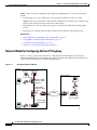
CH A P T E R
7
Provisioning: Configuring QoS for IP Telephony
In an Architecture for Voice, Video, and Integrated Data (AVVID) network, you must configure QoS for
IP telephony to ensure voice quality.
The following topics provide information about the need for configuring QoS in an IP telephony
environment and the tools that enable you to do this.
•
Understanding QoS for IP Telephony, page 7-1
•
Using QPM to Configure QoS for IP Telephony, page 7-3
•
Configuring QoS Using the IP Telephony Wizard, page 7-4
•
Modifying Voice Policies, page 7-17
•
Viewing the Voice Ready Report, page 7-18
•
Advanced IP Telephony Network Configuration, page 7-19
Understanding QoS for IP Telephony
Real-time based applications in a network, such as voice applications, have different characteristics and
requirements than those of data applications. Voice applications tolerate minimal variation in the amount
of delay affecting delivery of their voice packets.
Voice traffic is also intolerant of packet loss and jitter, both of which degrade the quality of the voice
transmission delivered to the recipient end user. To effectively transport voice traffic over IP,
mechanisms are required that ensure reliable delivery of packets with low latency.
In an enterprise environment, network congestion can occur at any time in any portion of the network
campus, branch office, or WAN. For successful deployment of IP telephony, you must ensure end-to-end
network quality for voice traffic.
To ensure voice quality, you must use QoS in all areas of the enterprise network. To make a proper QoS
configuration, you must first identify the points where QoS is a concern, then choose the appropriate
QoS tools to use, and deploy to the devices in the network.
User Guide for CiscoWorks QoS Policy Manager 4.1.6
OL-23444-01
7-1
Chapter 7
Provisioning: Configuring QoS for IP Telephony
Understanding QoS for IP Telephony
QPM provides tools that can determine and configure the optimum QoS for a voice network. These
include:
•
Provisioning tools—Lets you define the correct policies for interfaces on the voice paths.
QPM provides voice policies that contain the QoS configurations and traffic rules required at each
relevant point in the network that needs QoS for IP telephony.
•
Deployment tools—Lets you deploy these policies on the network and monitor the deployment
process.
•
Reporting tools—Graphs and charts help you identify and troubleshoot QoS related issues.
Related Topics
•
Network Model for Configuring QoS for IP Telephony, page 7-2
•
Using QPM to Configure QoS for IP Telephony, page 7-3
•
Viewing the Voice Ready Report, page 7-18
•
Chapter 9, “Provisioning: Deploying QoS Policies”
Network Model for Configuring QoS for IP Telephony
Figure 7-1 shows a typical network model for configuring QoS for IP telephony in an enterprise
environment. QPM supports the QoS methods required to configure IP telephony QoS for high-speed
campus domains, branch offices, and WAN implementations.
Figure 7-1
IP Telephony Network Model
Campus
SoftPhone CallManager
V
Remote Branch
2
3
Catalyst 6000
Access Switch
with PFC
1
IP
4
5
Catalyst 6000
Distribution switch
with PFC
7
IP
1
8
9
WAN
8
6
Catalyst 2900
Access Switch
Catalyst 3500
Access Switch
63130
1
IP
User Guide for CiscoWorks QoS Policy Manager 4.1.6
7-2
OL-23444-01
Chapter 7
Provisioning: Configuring QoS for IP Telephony
Using QPM to Configure QoS for IP Telephony
Table 7-1 explains the network points that require QoS configuration for IP telephony.
Table 7-1
Network Points Requiring QoS Configuration
Network Point
in Figure 7-1
Description
1
Access switch—IP phone ports
2
Layer 3 QoS-aware access switch (with PFC)—SoftPhone port
3
Layer 3 QoS-aware access switch (with PFC)—CallManager
port
4
Layer 3 QoS-aware access switch (with PFC) uplink port to
distribution switch (with PFC)
5
Distribution switch (downlink) port to Layer 3 QoS-aware
access switch (with PFC)
6
Distribution switch (downlink) port to Layer 2 QoS-aware
access switch
7
Layer 3 distribution switch port to WAN router
8
WAN interface
9
Branch office router interface to Layer 2 QoS-aware switch
Related Topics
•
Understanding QoS for IP Telephony, page 7-1
•
Using QPM to Configure QoS for IP Telephony, page 7-3
Using QPM to Configure QoS for IP Telephony
The QPM IP Telephony application provides a solution for configuring QoS for voice traffic in an
AVVID network.
The solution is an IP Telephony wizard that creates voice policies at each network point that requires IP
telephony QoS configuration.
Voice policies are policies that contain the QoS properties and traffic rules for each relevant point in the
IP telephony network. A voice policy contains a voice role attribute, which specifies the role of an
interface, according to its type, function and location on the network, such as, IP phone, Switch to WAN
Router. QPM allows you to modify properties and traffic rules of certain voice policies created by the
wizard, to suit specific network configurations, as required.
The IP Telephony wizard creates voice policies from voice policy templates which are provided by QPM
in the Policy Templates library. These templates follow the IP telephony QoS guidelines, described in
the IP Telephony QoS Design Guide:
www.cisco.com/warp/customer/771/srnd/qos_srnd.pdf
If the required templates do not exist during IP telephony QoS configuration, they can also be generated
by the wizard and stored in the library.
Some templates that are provided by QPM, such as ATM links, might not be used by the IP Telephony
wizard.
User Guide for CiscoWorks QoS Policy Manager 4.1.6
OL-23444-01
7-3
Chapter 7
Provisioning: Configuring QoS for IP Telephony
Configuring QoS Using the IP Telephony Wizard
You can also create voice policies without the wizard, using the voice policy templates supplied by QPM.
You assign the voice policies in the same way as you would data policies.
After you have completed the IP Telephony wizard, you can modify properties and policies of the voice
policies created by the voice wizard, to suit a specific network configuration.
Related Topics
•
Configuring QoS Using the IP Telephony Wizard, page 7-4
•
Modifying Voice Policies, page 7-17
•
Working with Policy Templates, page 6-4
Configuring QoS Using the IP Telephony Wizard
The IP Telephony wizard allows you to configure QoS for voice traffic on the network. The wizard
handles VoIP configuration in common IP telephony network topologies. It guides you through the steps
required to define your IP telephony network topology.
At each step, the wizard automatically creates the voice policies, that include the QoS properties and
traffic rules required at each network point (interface) where QoS is a concern. The wizard presents only
the interfaces on which the relevant QoS can be configured.
You need to select the network elements that require QoS configuration at each network point. The
wizard then automatically assigns the interfaces to the appropriate voice policies.
QPM allows you to import files which contain device role information about devices (see Removing
Devices, page 4-15). Device role information is used by the IP Telephony wizard during the selection of
interfaces to voice roles.
For example, for the wizard to select an Ethernet 10/100 port on the switch to an IP phone voice role,
the switch must be an access type switch (i.e., have an “access” device role). If the switch has a
“distribution” device role, QPM will not select it. If the device role information imported from a file is
not up-to-date, you can manually override it in the Device Properties page (see Viewing and Editing
Device Properties, page 4-10).
The wizard automatically creates voice policies in the current policy group. The policy group may also
contain previously created policies containing data traffic rules.
If required, you can change the current policy group when you start working with the wizard.
•
If the required voice policies already exist in the policy group, the wizard uses them and assigns the
required interfaces to them.
•
If a required voice policy does not exist in the policy group, the wizard creates a new one from the
relevant template.
Related Topics
•
Using QPM to Configure QoS for IP Telephony, page 7-3
•
Using the IP Telephony Wizard, page 7-5
•
Adding Devices to the Device Inventory, page 4-3
•
Working with Policy Templates, page 6-4
User Guide for CiscoWorks QoS Policy Manager 4.1.6
7-4
OL-23444-01
Chapter 7
Provisioning: Configuring QoS for IP Telephony
Configuring QoS Using the IP Telephony Wizard
Using the IP Telephony Wizard
This topic describes the following main features of the IP Telephony wizard pages, and how to use those
features:
•
Description, page 7-5
•
Advanced, page 7-5
•
Selection Table, page 7-5
•
Assignment Summary, page 7-5
•
Saving Your Assignments, page 7-6
Description
Each configuration step page of the wizard includes a description of the QoS policies that will be
configured on the interfaces for the selected voice role. You can view or hide this description by clicking
the arrow button next to Description. By default, the description is hidden.
Advanced
The Advanced section of a configuration step page provides two buttons:
•
Remove—This button opens a page in which you can remove network elements that were assigned
for a voice role.
This option allows you to change your selection of network elements after they have been assigned
to voice policies. The wizard removes the assignment of selected elements from the voice policy.
•
Recommend—If QPM recommended rules are available for a specific voice role, clicking this
button activates the wizard to accept the recommended selection of network elements for the current
voice role.
The network elements are selected but not assigned to voice policies. A list of the rules for the
current voice role is displayed.
You can view or hide the Advanced section by clicking the arrow button next to Advanced. By default,
this section is hidden.
Selection Table
In each configuration step, you select the network elements that require QoS configuration. The available
network elements are presented in a table. You can hide this table by clicking the arrow button next to
Selection Table. By default, the selection table is open. For information about using a selection table,
see Using QPM Tables, page 3-16.
By selecting the Display Configuration Info. check box in the first configuration step, you can choose to
view assignment summary information after each configuration step. The check box will remain selected
in all the other steps. Similarly, you can uncheck this check box in the first configuration step if you don’t
want to view the summary information. You can override the default selection at each step, if required.
Assignment Summary
As you work through the wizard, you can choose to view an assignment summary page that displays the
voice policies that were created for the current voice role, and summary information about the
assignment of network elements in the current configuration step.
User Guide for CiscoWorks QoS Policy Manager 4.1.6
OL-23444-01
7-5
Chapter 7
Provisioning: Configuring QoS for IP Telephony
Configuring QoS Using the IP Telephony Wizard
The following assignments summary information may be displayed:
•
The total number of network elements you selected in this configuration step.
•
The number of network elements that were selected, but found to be previously assigned to voice
policies with this voice role.
•
The number of network elements that were newly assigned to a voice policy with this voice role.
(This may include elements that were previously assigned to voice policy groups with different
voice roles.)
•
The number of network elements that were selected in this configuration step, but were not assigned
to the voice role because they have no policies for this voice role. These elements appear in the
selection list because they have the same interface type as other elements that can be selected.
For example, although GigabitEthernet interfaces have the same interface type as FastEthernet
interfaces, they cannot be connected to an IP phone. During IP phone configuration, these interfaces
will not be assigned to voice policy groups for the IP Phones voice role.
•
The number of related assignment elements. These are network elements that were not selected (or
were not in the selection table), but were assigned to voice policy groups to complete the
configuration correctly. For example, when you configure traffic shaping on a DLCI, you must also
enable it on a main frame-relay interface.
•
The number of reassigned network elements. If network elements were found to be already assigned
to voice policy groups with different voice roles, the wizard overrides the previous assignment and
assigns them to voice policies with the new voice role.
From this assignment summary page, you can also view detailed information about a voice policy group,
and a list of the newly assigned network elements.
Saving Your Assignments
You work through each step of the wizard by clicking the Next button in each page, or you can use the
Navigation TOC that is displayed on the left side of each page to move directly to the step you want to do.
Clicking Next to move to the next configuration step, or selecting another step forward in the Navigation
TOC, saves the voice policies and the assignments that were made for that voice role, to the deployment
group.
Clicking Cancel, Back, or selecting another step backward in the Navigation TOC, undoes any
configuration changes you made in that step.
If the Display Configuration Info check box is selected, clicking Next opens the assignments summary
page for that configuration step.
The voice policies will be saved in the policy group, but the assignment of interfaces to them will not be
saved.
After reviewing your assignments summary, clicking Next in this page saves both the voice policy
groups and the interface assignments, and opens the next step of the wizard.
Step-by-step procedures for configuring QoS using the IP Telephony wizard, are described in the
following sections.
•
Introduction
•
Selecting IP Telephony Devices
•
Selecting IP Phone Connections
•
Selecting SoftPhone Connections
•
Selecting CallManager Connections
User Guide for CiscoWorks QoS Policy Manager 4.1.6
7-6
OL-23444-01
Chapter 7
Provisioning: Configuring QoS for IP Telephony
Configuring QoS Using the IP Telephony Wizard
•
Selecting IntraLAN Connections
•
Selecting Voice VLAN Connections
•
Selecting Switch to WAN Router Connections
•
Selecting Router WAN to Switch Connections
•
Selecting WAN Point to Point Connections
•
Selecting WAN Frame Relay Connections
•
End
Before you Begin
To run the wizard, it is assumed that the following preconditions have been met:
•
Voice VLANs have been configured on all the relevant ports of the devices to enable the wizard to
attach QoS properties to these VLANs.
•
All the relevant devices in your network were added or imported to QPM’s device inventory.
Related Topics
•
Configuring QoS Using the IP Telephony Wizard, page 7-4
•
IP Telephony Wizard: Assignment Summary Page, page B-129
•
Viewing Policy Information, page 8-14
Introduction
The first page is an introduction to the wizard. It includes an overview of why QoS configuration is
necessary for VoIP networks, and how the wizard will guide you to configure QoS for IP telephony.
Before you run the wizard, ensure that all the required devices in your IP telephony network have been
added to the device inventory. If not, you must exit the wizard and add or import them. After adding your
devices, you can check that your devices support voice QoS, by running the Voice Ready report. The
Voice Ready report shows all the devices in the current device group, and whether or not they support
voice QoS.
This page also displays the name of the current deployment group that will be used by the wizard for
defining the IP telephony policies. You can change the current deployment group, if required.
To open the Introduction page of the wizard:
Step 1
Choose Provisioning > Policy View.
The Policy View page opens.
Step 2
Click Voice Policy.
The IP Telephony Wizard - Introduction page appears.
User Guide for CiscoWorks QoS Policy Manager 4.1.6
OL-23444-01
7-7
Chapter 7
Provisioning: Configuring QoS for IP Telephony
Configuring QoS Using the IP Telephony Wizard
If you are running the wizard for the first time, click the Before you run the wizard for the first time
link. A window opens, prompting you to check the following:
•
If you opened the wizard before adding or importing your devices into QPM’s device inventory,
click Cancel to exit the wizard, and add or import your devices before running the wizard.
•
Check if your devices support voice QoS by viewing the Voice Ready report. You can open this
report in one of the following ways:
•
Click the Voice Ready Report link in step 2 of the wizard.
•
Choose Reports > IP Telephony.
To change the displayed deployment group, select the required one from the list box.
Step 3
Click Next to move to the first configuration step of the wizard.
Related Topics
•
Selecting IP Telephony Devices, page 7-8
•
Adding Devices to the Device Inventory, page 4-3
•
Viewing the Voice Ready Report, page 7-18
Selecting IP Telephony Devices
In this step of the wizard, you select the devices that you want to participate in the current IP Telephony
wizard session. All the devices in the device group that support IP telephony features (according to
model and OS) are displayed in a table. The wizard will configure only the network elements from the
selected devices. By default, the wizard selects all the devices.
Devices that do not support IP telephony are not displayed. If required, you can open the Voice Ready
report to see all the devices in the current device group and whether or not they support QoS for voice.
If you opened the IP Telephony wizard before you added or imported your devices, no devices will be
displayed in the table. In this case, you must add or import devices into the device inventory.
Click Cancel to exit the wizard, and open the Add/Import Devices wizard (see Adding Devices to the
Device Inventory, page 4-3).
Some devices, such as Catalyst 6000 and Catalyst 4000 switches, require global device configuration. If
any of the selected devices require global device configuration, the wizard immediately assigns them to
the appropriate voice policy groups with a Voice Device voice role. Clicking the link on this page opens
an information window describing this feature.
To select IP Telephony devices:
Step 1
In the table, check the check boxes next to the devices you want to configure for voice QoS.
For more information about the columns in this table, see IP Telephony Wizard: Select IP Telephony
Devices Page, page B-128.
Step 2
To view the Voice Ready report, click the Voice Ready report link.
User Guide for CiscoWorks QoS Policy Manager 4.1.6
7-8
OL-23444-01
Chapter 7
Provisioning: Configuring QoS for IP Telephony
Configuring QoS Using the IP Telephony Wizard
Step 3
Select/deselect to view the Assignment Summary page:
•
If you want to view summary information about the assignments made at each configuration step of
the wizard, select the Display Configuration Info check box and click Next. The Assignment
Summary page appears.
For information about the Assignment Summary page, see IP Telephony Wizard: Assignment
Summary Page, page B-129.
•
Step 4
If you don’t want to view the assignments summary at each configuration step of the wizard,
uncheck the Display Configuration Info check box.
Click Next.
The voice policy groups and your network element assignments will be saved, and the next configuration
step of the wizard appears (Selecting IP Phone Connections).
Related Topics
•
Using QPM Tables, page 3-16
•
Adding Devices to the Device Inventory, page 4-3
•
Using the IP Telephony Wizard, page 7-5
•
Modifying Voice Policies, page 7-17
•
Viewing the Voice Ready Report, page 7-18
•
Viewing Policy Information, page 8-14
Selecting IP Phone Connections
This step of the wizard describes the QoS requirements for all catalyst ports to which IP phones are
connected, and asks you to select the switch ports on which the wizard will configure the QoS settings
for the IP phone connections (network point 1 in Figure 7-1).
To select IP phone connections:
Step 1
In the selection table, select the switch ports on which to configure QoS for your IP phones by selecting
the check boxes next to the appropriate Ethernet ports.
For more information about the columns in this table, see IP Telephony Wizard: Select IP Phone
Connections Page, page B-130.
Step 2
To remove any ports that were previously assigned for this voice role:
a.
Click the Remove button in the Advanced section of the page.
A page appears, displaying the network elements assigned for the IP Phones voice role.
For more information about this page, see IP Telephony Wizard: Remove Network Elements Page,
page B-132.
b.
Select the ports you want to unassign and click Remove.
The page closes.
User Guide for CiscoWorks QoS Policy Manager 4.1.6
OL-23444-01
7-9
Chapter 7
Provisioning: Configuring QoS for IP Telephony
Configuring QoS Using the IP Telephony Wizard
Step 3
Click Next.
If the Display Configuration Info. check box is selected, the Configuration Info page appears. After
reviewing the assignments summary, click Next.
The voice policy groups and your IP phones ports assignments will be saved, and the next configuration
step of the wizard appears (Selecting SoftPhone Connections).
Related Topics
•
Using QPM Tables, page 3-16
•
Using the IP Telephony Wizard, page 7-5
•
Viewing Policy Information, page 8-14
Selecting SoftPhone Connections
This step of the wizard describes the QoS requirements for a Catalyst 6000 (with PFC) switch that is
connected to a PC running a Cisco IP SoftPhone application.
You should select the switch ports on which the wizard will configure QoS settings for the SoftPhone
connections in your network (network point 2 in Figure 7-1).
To select SoftPhone connections:
Step 1
In the selection table, select the switch ports on which to configure QoS for the SoftPhone connections
in the network, by selecting the check boxes next to the appropriate Ethernet ports in the list.
For more information about the columns in this table, see IP Telephony Wizard: Select SoftPhone
Connections Page, page B-133.
Step 2
To remove any ports that were previously assigned for this voice role:
a.
Click the Remove button in the Advanced section of the page.
A page appears, displaying the network elements assigned for the SoftPhones voice role.
For more information about this page, see IP Telephony Wizard: Remove Network Elements Page,
page B-132.
b.
Select the ports you want to unassign and click Remove.
The page closes.
Step 3
Click Next.
If the Display Configuration Info. check box is selected, the Configuration Info page appears. After
reviewing the assignments summary, click Next.
The voice policy groups and your SoftPhones port assignments will be saved, and the next configuration
step of the wizard appears (Selecting CallManager Connections).
Related Topics
•
Using QPM Tables, page 3-16
•
Using the IP Telephony Wizard, page 7-5
•
Viewing Policy Information, page 8-14
User Guide for CiscoWorks QoS Policy Manager 4.1.6
7-10
OL-23444-01
Chapter 7
Provisioning: Configuring QoS for IP Telephony
Configuring QoS Using the IP Telephony Wizard
Selecting CallManager Connections
This step of the wizard describes the QoS requirements for Catalyst ports to which CallManagers or
Voice Gateways are connected, and asks you to select the switch ports on which the wizard will configure
the QoS settings for these connections in your network (network point 3 in Figure 7-1).
To select Call Manager connections:
Step 1
Select the switch port on which to configure QoS for the CallManager connection in the network, by
selecting the check box next to the appropriate Ethernet port in the selection table.
For information about the columns in this table, see IP Telephony Wizard: Select CallManager
Connections Page, page B-134.
Step 2
To remove any ports that were previously assigned for this voice role:
a.
Click the Remove button in the Advanced section of the page.
A page appears, displaying the network elements assigned for the CallManager voice role.
For more information about this page, see IP Telephony Wizard: Remove Network Elements Page,
page B-132.
b.
Select the ports you want to unassign and click Remove.
The page closes.
Step 3
Click Next.
If the Display Configuration Info. check box is selected, the Configuration Info page appears. After
reviewing the assignments summary, click Next.
The voice policy groups and your CallManager ports assignments will be saved, and the next
configuration step of the wizard appears (Selecting IntraLAN Connections).
Related Topics
•
Using QPM Tables, page 3-16
•
Using the IP Telephony Wizard, page 7-5
•
Viewing Policy Information, page 8-14
Selecting IntraLAN Connections
In this step, the wizard helps you define the appropriate QoS for the internal LAN ports—the uplinks
and downlinks (network points 4, 5 and 6 in Figure 7-1).
Note
No QoS configuration is required on the uplink port of the Layer 2 Catalyst 3500 switch to the Layer 3
distribution switch port.
The correct QoS configuration for LAN connections is to trust DSCP from Layer 3 devices and trust CoS
from Layer 2 devices. The wizard will configure the QoS automatically according to the type of
neighboring switch.
User Guide for CiscoWorks QoS Policy Manager 4.1.6
OL-23444-01
7-11
Chapter 7
Provisioning: Configuring QoS for IP Telephony
Configuring QoS Using the IP Telephony Wizard
If QPM recognizes that the neighboring switch has Layer 3 QoS capabilities, it will trust DSCP from the
Layer 3 switch. If there is no neighboring switch (or if the switch is of unknown type), QPM will
configure QoS for a Layer 2 device.
To select IntraLAN connections:
Step 1
Select the switch interfaces on which to configure QoS for the LAN connections in the network, by
selecting the check boxes next to the appropriate interfaces in the selection table.
For more information about the columns in this table, see IP Telephony Wizard: Select IntraLAN
Connections Page, page B-136.
Step 2
To remove any interfaces that were previously assigned for this voice role:
a.
Click the Remove button in the Advanced section of the page.
A page appears, displaying the network elements assigned for the IntraLAN voice role.
For more information about this page, see IP Telephony Wizard: Remove Network Elements Page,
page B-132.
b.
Select the interfaces you want to unassign and click Remove.
The page closes.
Step 3
Click Next.
If the Display Configuration Info. check box is selected, the Configuration Info page appears. After
reviewing the assignments summary, click Next.
The voice policy groups and your LAN interfaces assignments will be saved, and the next configuration
step of the wizard appears (Selecting Voice VLAN Connections).
Related Topics
•
Using QPM Tables, page 3-16
•
Using the IP Telephony Wizard, page 7-5
•
Viewing Policy Information, page 8-14
Selecting Voice VLAN Connections
Since the IP phone ports are configured to use an auxiliary voice VLAN on the switches, and the QoS
style on the IP phone ports is set to VLAN-based, it is important to attach the appropriate policies to the
voice VLAN.
In this step, the wizard configures VLAN-based QoS style for an auxiliary VLAN on the connection of
the IP phones to the Catalyst 6000 access switch, and also on the Layer 2 switch to Layer 3 switch
connection.
User Guide for CiscoWorks QoS Policy Manager 4.1.6
7-12
OL-23444-01
Chapter 7
Provisioning: Configuring QoS for IP Telephony
Configuring QoS Using the IP Telephony Wizard
To select Voice VLAN connections:
Step 1
In the selection table, select the auxiliary VLANs on which to configure QoS on both the access and
distribution layer switches.
For more information about the columns in this table, see IP Telephony Wizard: Select Voice VLAN
Connections Page, page B-138.
Step 2
To remove any VLANs that were previously assigned for this voice role:
a.
Click the Remove button in the Advanced section of the page.
A page appears, displaying the VLANs assigned for the Voice VLAN voice role.
For more information about this page, see IP Telephony Wizard: Remove Network Elements Page,
page B-132.
b.
Select the VLANs you want to unassign and click Remove.
The page closes.
Step 3
Click Next.
If the Display Configuration Info. check box is selected, the Configuration Info page appears. After
reviewing the assignments summary, click Next.
The voice policy groups and your Voice VLAN assignments will be saved, and the next configuration
step of the wizard appears (Selecting Switch to WAN Router Connections).
Related Topics
•
Using QPM Tables, page 3-16
•
Using the IP Telephony Wizard, page 7-5
•
Viewing Policy Information, page 8-14
•
Troubleshooting the IP Telephony Network, page 14-14
Selecting Switch to WAN Router Connections
In this step, the wizard sets QoS for the distribution switch interfaces to the WAN router (network point
7 in Figure 7-1).
Since the traffic coming from the WAN side is already classified, the QoS configuration for the
distribution switch interface to the router will be to trust the layer 3 DSCP bits.
To select Switch to WAN Router connections:
Step 1
Select the switch interface on which to configure QoS for the distribution switch connection to the WAN
router, by selecting the check box next to the appropriate port in the selection table.
For more information about the columns in this table, see IP Telephony Wizard: Select Switch to WAN
Router Connections Page, page B-140.
Step 2
To remove any interfaces that were previously assigned for this voice role:
a.
Click the Remove button in the Advanced section of the page.
A page appears, displaying the interfaces assigned for the Switch to WAN Router voice role.
User Guide for CiscoWorks QoS Policy Manager 4.1.6
OL-23444-01
7-13
Chapter 7
Provisioning: Configuring QoS for IP Telephony
Configuring QoS Using the IP Telephony Wizard
For more information about this page, see IP Telephony Wizard: Remove Network Elements Page,
page B-132.
b.
Select the interfaces you want to unassign and click Remove.
The page closes.
Step 3
Click Next.
If the Display Configuration Info. check box is selected, the Configuration Info page appears. After
reviewing the assignments summary, click Next.
The voice policy groups and your Switch-to-WAN-Router interface assignments will be saved, and the
next configuration step of the wizard appears (Selecting Router WAN to Switch Connections).
Related Topics
•
Using QPM Tables, page 3-16
•
Using the IP Telephony Wizard, page 7-5
•
Viewing Policy Information, page 8-14
Selecting Router WAN to Switch Connections
In this step, the wizard sets QoS for the WAN router connection to the access (layer 2 QoS aware) switch
in the branch office (network point 9 in Figure 7-1).
By default, a router trusts the interface to a distribution (layer 3 QoS aware) switch, so no special QoS
is required on the router input direction.
For example, in Figure 7-1, there is no need to set QoS for the router connection to the Catalyst 6000
distribution switch in the campus. In addition, no special QoS is required on the output direction, since
the layer 3 switch knows to trust DSCP from the router and sets the CoS bits accordingly. However, if
the switch has only layer 2 QoS capabilities, the router must classify traffic on input and set layer 2 CoS
bits on output.
To select Router WAN to Switch connections:
Step 1
Select the switch interfaces on which to configure QoS for the router interfaces to the distribution and
access switches, by selecting the check boxes next to the appropriate interfaces in the list.
For more information about the columns in this table, see IP Telephony Wizard: Select Router WAN to
Switch Connections Page, page B-141.
Step 2
To remove any interfaces that were previously assigned for this voice role:
a.
Click the Remove button in the Advanced section of the page.
A page appears, displaying the interfaces assigned for the Router WAN to Switch voice role.
For more information about this page, see IP Telephony Wizard: Remove Network Elements Page,
page B-132.
b.
Select the interfaces you want to unassign and click Remove.
The page closes.
Step 3
Click Next.
User Guide for CiscoWorks QoS Policy Manager 4.1.6
7-14
OL-23444-01
Chapter 7
Provisioning: Configuring QoS for IP Telephony
Configuring QoS Using the IP Telephony Wizard
If the Display Configuration Info. check box is selected, the Configuration Info page appears. After
reviewing the assignments summary, click Next.
The voice policy groups and your Router-to-Switch interface assignments will be saved, and the next
configuration step of the wizard appears (Selecting WAN Point to Point Connections).
Related Topics
•
Using QPM Tables, page 3-16
•
Using the IP Telephony Wizard, page 7-5
•
Viewing Policy Information, page 8-14
Selecting WAN Point to Point Connections
This step of the wizard allows you to select the interfaces on which to configure QoS for the Serial
Point-to-Point links in the WAN segment of your network. You should select all MLP and HDLC
interfaces (from both the central and the remote sites) that carry voice traffic.
For Point-to-Point links with speeds equal to or less than 768 kbs, you should select Multilink
interfaces—selecting a serial interface may cause a deployment failure.
The wizard will automatically configure QoS separately for groups of interfaces with link speeds greater
than 768kbs, and those with link speeds equal to or less than 768kbs.
In certain types of configurations where the rate of a multilink interface is not defined, and the serial
bandwidth is less than or equal to 768 kbits, the IP Telephony wizard assigns the multilink interfaces to
high speed policy groups instead of low speed policy groups.
To make the correct assignment in the IP Telephony wizard, you must define the bandwidth on the
multilink interface using the device’s bandwidth CLI command.
To select WAN Point to Point connections:
Step 1
Select the interfaces on which to configure QoS for the WAN Serial Point-to-Point links, by selecting
the check boxes next to the appropriate interfaces in the list.
For more information about the columns in this table, see IP Telephony Wizard: Select WAN Point to
Point Connections Page, page B-143.
Step 2
To remove any interfaces that were previously assigned for this voice role:
a.
Click the Remove button in the Advanced section of the page.
A page appears, displaying the interfaces assigned for the WAN Point-to-Point voice role.
For more information about this page, see IP Telephony Wizard: Remove Network Elements Page,
page B-132.
b.
Select the interfaces you want to unassign and click Remove.
The page closes.
Step 3
Click Next.
If the Display Configuration Info. check box is selected, the Configuration Info page appears. After
reviewing the assignments summary, click Next.
User Guide for CiscoWorks QoS Policy Manager 4.1.6
OL-23444-01
7-15
Chapter 7
Provisioning: Configuring QoS for IP Telephony
Configuring QoS Using the IP Telephony Wizard
The voice policy groups and your WAN-Serial-Point-to-Point interface assignments will be saved, and
the next configuration step of the wizard appears (Selecting WAN Frame Relay Connections).
Related Topics
•
Using QPM Tables, page 3-16
•
Using the IP Telephony Wizard, page 7-5
•
Viewing Policy Information, page 8-14
•
Troubleshooting the IP Telephony Network, page 14-14
Selecting WAN Frame Relay Connections
If the interface connections in the WAN segment of your network support Frame Relay configuration,
this step of the wizard allows you to select the Frame Relay DLCI’s WAN links. When you assign a role
to a DLCI, the role will also be assigned to the interface to which the DLCI belongs. QPM will configure
both the DLCIs and the interfaces.
Note
The IP Telephony wizard currently supports only Frame Relay to Frame Relay network configuration,
and not Frame Relay to ATM configuration. QPM does include templates for Frame Relay to ATM
connections; see Configuring QoS on ATM to Frame Relay Connections, page 7-20. QPM also includes
ATM templates; see Configuring QoS on ATM Connections, page 7-20.
The wizard describes the tools that will be used to configure the QoS settings for these interfaces.
You must select all the Frame Relay interfaces (from both the central and the remote sites) that carry
voice traffic. The wizard will automatically configure QoS separately for groups of interfaces, according
to their link speed.
To select WAN Frame Relay connections:
Step 1
Select the interfaces on which to configure QoS for the Frame Relay WAN links, by selecting the check
boxes next to the appropriate Frame Relay interfaces in the list.
For more information about the columns in this table, see IP Telephony Wizard: Select WAN Frame
Relay Connections Page, page B-145.
Step 2
To remove any interfaces that were previously assigned for this voice role:
a.
Click the Remove button in the Advanced section of the page.
A page appears, displaying the interfaces assigned for the WAN Frame Relay voice role.
For more information about this page, see IP Telephony Wizard: Remove Network Elements Page,
page B-132.
b.
Select the interfaces you want to unassign and click Remove.
The page closes.
Step 3
Click Next.
If the Display Configuration Info. check box is selected, the Configuration Info page appears. After
reviewing the assignments summary, click Next.
User Guide for CiscoWorks QoS Policy Manager 4.1.6
7-16
OL-23444-01
Chapter 7
Provisioning: Configuring QoS for IP Telephony
Modifying Voice Policies
The voice policy groups and your WAN-Frame-Relay interface assignments will be saved, and the last
step of the wizard appears (End, page 7-17).
Related Topics
•
Using QPM Tables, page 3-16
•
Using the IP Telephony Wizard, page 7-5
•
Viewing Policy Information, page 8-14
•
Troubleshooting the IP Telephony Network, page 14-14
End
The final step of the IP Telephony wizard informs you that all the QoS settings have been completed and
that the wizard has added and saved the policies in the current deployment group.
From this page, you can select to go to the Deployment wizard to deploy the deployment group directly,
or to the Policy Groups page to view a detailed summary of all the voice policy groups that were created
by the wizard. From the Policy Groups page, you can modify the properties and policies configured in
the voice policy groups, if required.
To finish the wizard:
Step 1
Select the Yes or No radio button, depending on whether or not you want to deploy your QoS policies.
Step 2
Click Finish to close the wizard.
The Policy Groups page or the Deployment wizard appears.
Related Topics
•
Modifying Voice Policies, page 7-17
•
Modifying a Policy, page 8-15
•
Chapter 9, “Provisioning: Deploying QoS Policies”
Modifying Voice Policies
After you have completed the IP Telephony wizard, you can modify properties and traffic rules of the
voice policies created by the voice wizard, to suit a specific network configuration. You can also add
nonvoice rules to the default voice policies.
Note
You cannot modify a voice policy that is linked to a policy template. You must disconnect the voice
policy from its template, or modify the template.
After you have completed the IP Telephony wizard and you selected not to deploy your QoS policies
directly (see End, page 7-17), the Policy View page automatically appears.
User Guide for CiscoWorks QoS Policy Manager 4.1.6
OL-23444-01
7-17
Chapter 7
Provisioning: Configuring QoS for IP Telephony
Viewing the Voice Ready Report
The Policy View page displays all voice policies together with non voice policies in the current policy
group. For each voice policy, its associated voice role is displayed.
You can modify any of the properties and traffic rules of a voice policy, except for its device constraints.
Changing the device constraints will cause the voice policy to lose its voice role.
In this case, the IP Telephony wizard will be unable to assign network elements to the voice policy. You
edit a voice policy just like any policy. The difference is that when saving, QPM checks the device
constraints of the voice policy. If any changes were made, you must save the voice policy as a regular
policy without a voice role.
A full description of modifying policies is provided in Modifying a Policy, page 8-15.
Related Topics
•
Using QPM to Configure QoS for IP Telephony, page 7-3
Viewing the Voice Ready Report
The Voice Ready report provides you with an overview of the system’s readiness for voice, displaying a
list of all the configurable and nonconfigurable devices in the current device group.
The report displays the voice ready status of each device, and the reason for nonvoice readiness, where
relevant. For a device to be “voice ready”, it must have all the required software and hardware to support
QoS for voice and be supported by QPM.
Nonconfigurable devices do not have the required software or hardware to support QoS for voice, and/or
are not supported by QPM. From this report, you can also view the properties of the devices in the list.
Note
Some devices that appear as “voice ready” in the report may not be supported by the IP Telephony
wizard. They must be configured manually by QPM.
We recommend that you view the Voice Ready report after adding or importing the devices in your IP
telephony network to QPM’s device inventory, so that you can check whether your devices support voice
QoS.
In the second step of the IP Telephony wizard, only the devices that support IP telephony features are
displayed in a table. Devices that do not support IP telephony are not displayed. By opening the Voice
Ready report, you can see all the devices in the current device group, including those that do not support
QoS for voice.
To view the Voice Ready Report:
Step 1
In Step 2 (Select Devices) of the IP Telephony wizard, click the Voice Ready Report link
The Voice Ready report appears, displaying the voice status of each device and the reason for non voice
readiness, where relevant.
Step 2
To view details about a device in the table, click the Sys Name link for the required device in the table.
The Device Properties page appears for the selected device.
User Guide for CiscoWorks QoS Policy Manager 4.1.6
7-18
OL-23444-01
Chapter 7
Provisioning: Configuring QoS for IP Telephony
Advanced IP Telephony Network Configuration
Related Topics
•
Introduction, page 7-7
•
Selecting IP Telephony Devices, page 7-8
•
Using QPM Tables, page 3-16
•
Viewing and Editing Device Properties, page 4-10
Advanced IP Telephony Network Configuration
Although QPM’s IP Telephony wizard can configure many of the QoS requirements for an AVVID
network, there are some potential configurations you might need to consider that are beyond the scope
of the wizard. These topics describe some of these configuration issues:
•
Policing SoftPhone Traffic, page 7-19
•
Configuring QoS on ATM Connections, page 7-20
•
Configuring QoS on ATM to Frame Relay Connections, page 7-20
In addition to these topics, see the Cisco AVVID Network Infrastructure Enterprise Quality of Service
Design Guide, which provides a blueprint for implementing the end-to-end Quality of Service (QoS).
This QoS is required for successful deployment of Cisco AVVID solutions in today's enterprise
environment. It is located at:
www.cisco.com/warp/customer/771/srnd/qos_srnd.pdf
Policing SoftPhone Traffic
On a Catalyst port that is connected to a PC running a Cisco IP SoftPhone application, the IP Telephony
wizard marks all the VoIP traffic with DSCP value 46, and all the control traffic with DSCP 26. If PC
users begin sending non-priority traffic using the VoIP UDP ports or the CTI TCP port, this non-priority
traffic will receive the same quality of service from the network as VoIP traffic or VoIP control traffic.
You can configure policing on the inbound traffic of the Catalyst port to prevent the PC from flooding
the queues for DSCP 46 traffic.
For example:
•
You can police VoIP traffic at a rate of 100kbps with a burst of 2kb.
•
You can police control traffic at 8kbps (configure 32kbs) with a burst of 8kb.
You should also set the markdown table on the device from DSCP 46 to 0, and DSCP 26 to 0.
User Guide for CiscoWorks QoS Policy Manager 4.1.6
OL-23444-01
7-19
Chapter 7
Provisioning: Configuring QoS for IP Telephony
Advanced IP Telephony Network Configuration
Configuring QoS on ATM Connections
The QPM IP Telephony wizard does not configure ATM connections. However, QPM includes templates
that you can use to create policy groups for your ATM interfaces.
To configure QoS on ATM Connections:
Step 1
Create and bind virtual template interfaces on the ATM PVC.
For example, the bolded command in this configuration example shows the commands for binding
virtual templates to the ATM PVC. See the configuration documentation for your device for information
on creating virtual templates.
interface ATM4/0.60 point-to-point
protocol ppp Virtual-Template60
!
interface Virtual-Template60
bandwidth 256
ip address 10.200.60.1 255.255.255.252
ppp multilink
If you have already added the devices to QPM, rediscover the devices in QPM so that the virtual template
interfaces are recognized. See Rediscovering Device Information, page 4-12.
Otherwise, add the devices to QPM (see Adding Devices to the Device Inventory, page 4-3).
Step 2
Step 3
Create policy groups from these QPM templates, and assign them to the described interfaces.
•
WanATMVirtualTemplate—Assign to the ATM virtual template interfaces.
•
WanATMHighSpeed—Assign to the ATM PVC for interfaces greater than 768kbps.
Deploy the policies. See Deploying Policies and QoS Configurations, page 9-2.
Configuring QoS on ATM to Frame Relay Connections
Some networks use ATM at the main site, but Frame Relay at remote sites, for communicating between
the main and remote sites. If your network uses this setup, you can use QPM’s ATM to Frame Relay IP
telephony templates to deploy QoS on the ATM and Frame Relay interfaces.
To support IP telephony, low speed interfaces (less than 768kbps) must enable link fragmentation and
interleaving. For ATM to Frame Relay connections, this can be done using Multilink PPP (MLP) over
ATM or Frame Relay. This procedure describes how to configure this setup.
To configure QoS on ATM to Frame Relay Connections:
Step 1
Create and bind virtual template interfaces on the ATM PVC and the Frame Relay DLCI.
For example, the bolded commands in these configuration examples show the commands for binding
virtual templates to the ATM PVC (Example 7-1)and Frame Relay DLCI (Example 7-2). See the
configuration documentation for your device for information on creating virtual templates.
User Guide for CiscoWorks QoS Policy Manager 4.1.6
7-20
OL-23444-01
Chapter 7
Provisioning: Configuring QoS for IP Telephony
Advanced IP Telephony Network Configuration
Example 7-1
ATM PVC Virtual Template
interface ATM4/0.60 point-to-point
protocol ppp Virtual-Template60
!
interface Virtual-Template60
bandwidth 256
ip address 10.200.60.1 255.255.255.252
ppp multilink
Example 7-2
Frame Relay DLCI Virtual Template
!
interface Serial6/0
no ip address
encapsulation frame-relay
!
interface Serial6/0.60 point-to-point
bandwidth 256
frame-relay interface-dlci 60 ppp Virtual-Template60
!
interface Virtual-Template60
bandwidth 256
ip address 10.200.60.2 255.255.255.252
ppp multilink
If you have already added the devices to QPM, rediscover the devices in QPM so that the virtual template
interfaces are recognized. See Rediscovering Device Information, page 4-12.
Otherwise, add the devices to QPM (see Adding Devices to the Device Inventory, page 4-3).
Step 2
Step 3
Create policy groups from these QPM templates, and assign them to the described interfaces.
•
WanATM2FR-FR-Main—Assign to the main Frame Relay interface.
•
WanATM2FRVirtualTemplate—Assign to both the ATM and Frame Relay virtual template
interfaces.
•
WanATM2FR-FR-DLCI—Assign to the Frame Relay DLCI.
•
WanATM2FR-ATM-PVC—Assign to the ATM PVC.
Deploy the policies. See Deploying Policies and QoS Configurations, page 9-2.
User Guide for CiscoWorks QoS Policy Manager 4.1.6
OL-23444-01
7-21
Chapter 7
Provisioning: Configuring QoS for IP Telephony
Advanced IP Telephony Network Configuration
User Guide for CiscoWorks QoS Policy Manager 4.1.6
7-22
OL-23444-01