1
Ciprico Disk Array . . . . . . . .
6500 Disk Array
User’s Guide
Ciprico Inc.
Publication 21020690 B
©1996 by Ciprico Inc.
All rights reserved. No part of this publication may be reproduced or transmitted
in any form, or by any means, electronic or mechanical (including
photocopying and recording), or by any information storage or retrieval system,
without the permission of Ciprico Inc.
Printed in the United States of America
Rimfire is a trademark of Ciprico Inc.
Chapter
Page 4
Programmer Reference
Preface
This guide contains all the information needed to successfully install,
operate, and maintain Ciprico’s 6500 Disk Array subsystems in
standard configurations. If you need more technical information for
non-standard applications, refer to the Ciprico 6500 Controller Board
Technical Reference (available from Ciprico).
The standard 6500 array contains eight data drives and one parity drive.
The array is equipped with a Wide Ultra SCSI interface, providing
transfer rates up to 40MB per second.
Ciprico 6500 arrays readily fit into any standard SCSI platform
environment, including DEC, HP, IBM, Silicon Graphics (SGI), Sun,
and PC.
Note Different model numbers identify 6500 subsystems as
single-ended (Model 6511) or differential (Model 6512).
In this guide, references to 6500 disk arrays apply to both
models unless specifically stated otherwise.
In This Guide
Notational
Conventions
Chapter 1
Description
Chapter 2
Installation
Chapter 3
Display/Operation Panel
Chapter 4
Maintenance, Troubleshooting & Hardware
Replacement
The following notational conventions are used throughout this guide:
•
An uppercase letter “H” following a number indicates that the
number is a hexadecimal value, e.g., 20H and FFH.
•
In this guide, a byte is defined as an 8-bit quantity.
•
Note is used in the text to indicate emphasized or supplemental
information.
•
Caution is used in the text to indicate a condition that could
destroy data or damage equipment.
•
Warning is used in the text to indicate a condition that could
cause injury to the operator or technician.
Page ii
Preface
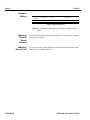
Revision
History
Publication
Number
21020690
21020690
Revision
Date
Description
A
B
09.96
11.96
First release
Updated for production release
Figure 1 Revision History
Note The information in this document is subject to change without
notice.
21020690 B
Warning:
Fire and
Shock
Hazards
To prevent the hazards of fire and electrical shock, do not expose this product
to any type of moisture.
Warning:
Power Cord
In case of emergency, unplug the power cord from the back of the unit to ensure
that no power is applied to the unit.
6500 Disk Array User’s Guide
Preface
Electromagnetic
Compatibility
Page iii
United States
This equipment has been tested and found to comply with the limits of a Class
A computing device in accordance with the specifications set forth in Part 15
of the FCC Rules. If this equipment does cause interference to radio or
television reception, which can be determined by turning the equipment on and
off, use the equipment in another location and/or utilize an electrical outlet
different from that used by the receiver. The user should use special accessories,
such as a shielded cable, as recommended in these operating instructions, in
order to continue to meet FCC emission limits and not possibly interfere with
nearby radio and television reception.
Canada
This digital apparatus does not exceed the Class A limits for radio noise for
digital apparatus set out on the Radio Interference Regulations of the Canadian
Department of Communications.
Cet èquipement èlectronique ne dèpasse pas la limite de la classe A pour le
bruit èlectromagnètique dèfinie pour les appareils èlectroniques numèriques
par la règlementation sur les radio interfèrences des Services Canadiens des
tèlècommunications.
Germany
Hiermit wird bescheinigt, dass das Gerät AS6511 und AS6512 Disk Array
subsystems in Übereinstimmung mid den Bestimmungen der Vfg 1046/1984
funkentstört ist.
Der Deutschen Bundespost wurde das Inverkehrbringen dieses Gerätes
angezeigt und die Berechtigung zur Überprüfung der 6500 auf Einhaltung der
Bestimmung eingeräumt.
6500 Disk Array User’s Guide
21020690 B
Page iv
Preface
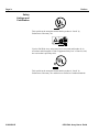
Safety
Listings and
Certification
This symbol on the nameplate means that the product is “listed” by
Underwriters Laboratory Inc.
Ciprico 6500 Disk Array subsystems have been tested and found to be in
accordance with Paragraph 3 of the “Equipment Safety Law” of June 24, 1968,
the version that is presently valid.
This symbol on the nameplate means that the product is “listed” by
Underwriters Laboratory Inc. and has been certified to Canadian standards.
21020690 B
6500 Disk Array User’s Guide
Table of Contents
Page v
Table of
Contents
1
Preface . . . . . . . . . . . . . . . . . . . . . . . . . . . . . . . . . . . . . . . . . . . .
In This Guide . . . . . . . . . . . . . . . . . . . . . . . . . . . . . . . . . . . .
Notational Conventions . . . . . . . . . . . . . . . . . . . . . . . . . . . .
Revision History . . . . . . . . . . . . . . . . . . . . . . . . . . . . . . . . .
Warning:
Fire and Shock
Hazards . . . . . . . . . . . . . . . . . . . . . . . . . . . . . . . . . . . . . . . . . . . . . . .
Warning:
Power Cord . . . . . . . . . . . . . . . . . . . . . . . . . . . . . . . . . . . . . . . . . . . .
Electro-magnetic
Compatibility . . . . . . . . . . . . . . . . . . . . . . . . . . . . . . . . . . . . . . . . . .
United States . . . . . . . . . . . . . . . . . . . . . . . . . . . . . . . . .
Canada. . . . . . . . . . . . . . . . . . . . . . . . . . . . . . . . . . . . . .
Germany . . . . . . . . . . . . . . . . . . . . . . . . . . . . . . . . . . . .
Safety Listings and Certification . . . . . . . . . . . . . . . . . . . . .
i
i
i
ii
iii
iii
iii
iii
iv
Description . . . . . . . . . . . . . . . . . . . . . . . . . . . . . . . . . . . . . . . . . . . .
1-1
In This Chapter. . . . . . . . . . . . . . . . . . . . . . . . . . . . . . . . . . . . . .
1-2
6500 Disk Array Functions and Application . . . . . . . . . . . . . . .
1-3
Features and Options . . . . . . . . . . . . . . . . . . . . . . . . . . . . . . . . .
SCSI Compatibility . . . . . . . . . . . . . . . . . . . . . . . . . . . . . . .
Controller Board . . . . . . . . . . . . . . . . . . . . . . . . . . . . . . . . .
Disk Drives . . . . . . . . . . . . . . . . . . . . . . . . . . . . . . . . . . . . .
Redundancy . . . . . . . . . . . . . . . . . . . . . . . . . . . . . . . . . . . . .
Parallel Disk Array Architecture . . . . . . . . . . . . . . . . . . . . .
Parity Drive . . . . . . . . . . . . . . . . . . . . . . . . . . . . . . . . . . . . .
16-Bit Wide Synchronous Transfer . . . . . . . . . . . . . . . . . . .
Single-Ended or Differential Signals. . . . . . . . . . . . . . . . . .
Enclosure . . . . . . . . . . . . . . . . . . . . . . . . . . . . . . . . . . . . . . .
1-4
1-4
1-4
1-4
1-4
1-4
1-4
1-5
1-5
1-5
ii
ii
Primary
Components . . . . . . . . . . . . . . . . . . . . . . . . . . . . . . . . . . . . . . . . . . .
Enclosure . . . . . . . . . . . . . . . . . . . . . . . . . . . . . . . . . . . . . . .
Air Filter . . . . . . . . . . . . . . . . . . . . . . . . . . . . . . . . . . . . . . .
Controller
Board. . . . . . . . . . . . . . . . . . . . . . . . . . . . . . . . . . . . . . . . . . . . . . . . .
Display/Operation Panel . . . . . . . . . . . . . . . . . . . . . . . . . . .
Disk Drives . . . . . . . . . . . . . . . . . . . . . . . . . . . . . . . . . . . . .
Fans and Temperature Sensor . . . . . . . . . . . . . . . . . . . . . . .
Power Supply. . . . . . . . . . . . . . . . . . . . . . . . . . . . . . . . . . . .
Display/Operation Panel . . . . . . . . . . . . . . . . . . . . . . . . . . .
Liquid Crystal Display (LCD) . . . . . . . . . . . . . . . . . . .
RESET Switch . . . . . . . . . . . . . . . . . . . . . . . . . . . . . . .
SELECT Switch . . . . . . . . . . . . . . . . . . . . . . . . . . . . . .
Navigation Switches (Up, Down, Left, Right) . . . . . . .
1-6
1-6
1-6
1-6
1-6
1-8
1-8
1-8
1-8
1-8
Rear Panel Switches and Connectors . . . . . . . . . . . . . . . . . . . . .
SCSI Connectors . . . . . . . . . . . . . . . . . . . . . . . . . . . . . . . . .
Activity LED . . . . . . . . . . . . . . . . . . . . . . . . . . . . . . . . . . . .
Power ON/OFF Switch . . . . . . . . . . . . . . . . . . . . . . . . . . . .
Power Cord Connectors. . . . . . . . . . . . . . . . . . . . . . . . . . . .
1-9
1-9
1-9
1-9
1-9
6500 Disk Array User’s Guide
1-6
1-6
1-6
21020690 B
Table of Contents
Page vi
2
3
21020690 B
Power Voltage Selection Switch . . . . . . . . . . . . . . . . . . . . .
1-9
Installation. . . . . . . . . . . . . . . . . . . . . . . . . . . . . . . . . . . . . . . . . . . . .
2-1
In This Chapter . . . . . . . . . . . . . . . . . . . . . . . . . . . . . . . . . . . . . .
2-2
Installation Procedure. . . . . . . . . . . . . . . . . . . . . . . . . . . . . . . . .
Step 1.
Move Array to Operation Site. . . . . . . . . . . . . . . . . . . . . . . . . . . . . .
Step 2.
Mount Enclosure . . . . . . . . . . . . . . . . . . . . . . . . . . . . . . . . . . . . . . . .
Step 3.
Attach SCSI Cable . . . . . . . . . . . . . . . . . . . . . . . . . . . . . . . . . . . . . .
Step 4.
Terminate SCSI Bus, if Necessary . . . . . . . . . . . . . . . . . . . . . . . . . .
Step 5.
Set Array Input Voltage Switch . . . . . . . . . . . . . . . . . . . . . . . . . . . .
Step 6.
Attach Power Cord . . . . . . . . . . . . . . . . . . . . . . . . . . . . . . . . . . . . . .
Step 7.
Power Up the Array . . . . . . . . . . . . . . . . . . . . . . . . . . . . . . . . . . . . .
Step 8.
Check Array Status . . . . . . . . . . . . . . . . . . . . . . . . . . . . . . . . . . . . . .
Drive Status . . . . . . . . . . . . . . . . . . . . . . . . . . . . . . . . . .
Drive Status Codes . . . . . . . . . . . . . . . . . . . . . . . . . . . .
Step 9.
Configure the Array . . . . . . . . . . . . . . . . . . . . . . . . . . . . . . . . . . . . .
Step 10.
Power Up the Host System . . . . . . . . . . . . . . . . . . . . . . . . . . . . . . . .
2-3
2-3
2-3
2-3
2-3
2-4
2-4
2-4
2-4
2-4
2-5
2-5
2-5
Display/Operation Panel . . . . . . . . . . . . . . . . . . . . . . . . . . . . . . . . . .
3-1
In This Chapter . . . . . . . . . . . . . . . . . . . . . . . . . . . . . . . . . . . . . .
3-2
Controls and Indicators . . . . . . . . . . . . . . . . . . . . . . . . . . . . . . .
3-3
Operation Guidelines . . . . . . . . . . . . . . . . . . . . . . . . . . . . . . . . .
Array Power-Up and Built-In Self-Test (BIST) . . . . . . . . .
Initial Display . . . . . . . . . . . . . . . . . . . . . . . . . . . . . . . . . . .
Tree-Structured Menu . . . . . . . . . . . . . . . . . . . . . . . . . . . . .
Changing or Selecting a Menu Option . . . . . . . . . . . . . . . .
Saving Changes . . . . . . . . . . . . . . . . . . . . . . . . . . . . . . . . . .
Default Settings . . . . . . . . . . . . . . . . . . . . . . . . . . . . . . . . . .
3-4
3-4
3-4
3-4
3-5
3-5
3-5
ARRAY OPTIONS . . . . . . . . . . . . . . . . . . . . . . . . . . . . . . . . . .
ON/OFF LINE . . . . . . . . . . . . . . . . . . . . . . . . . . . . . . . . . . .
SCSI ID . . . . . . . . . . . . . . . . . . . . . . . . . . . . . . . . . . . . . . . .
PASSWORD . . . . . . . . . . . . . . . . . . . . . . . . . . . . . . . . . . . .
Clear Password . . . . . . . . . . . . . . . . . . . . . . . . . . . . . . .
UNIT ATTENTION . . . . . . . . . . . . . . . . . . . . . . . . . . . . . .
WRITE PROTECT . . . . . . . . . . . . . . . . . . . . . . . . . . . . . . .
ALARM . . . . . . . . . . . . . . . . . . . . . . . . . . . . . . . . . . . . . . . .
SET DEFAULTS . . . . . . . . . . . . . . . . . . . . . . . . . . . . . . . . .
3-11
3-11
3-11
3-12
3-13
3-13
3-13
3-13
3-14
6500 Disk Array User’s Guide
Table of Contents
Page vii
RPT AS RECOVER . . . . . . . . . . . . . . . . . . . . . . . . . . . . . .
TEMP WARNING . . . . . . . . . . . . . . . . . . . . . . . . . . . . . . .
TEMP CRITICAL . . . . . . . . . . . . . . . . . . . . . . . . . . . . . . . .
AUTO MEGOMETER (ON/OFF) . . . . . . . . . . . . . . . . . . .
ARRAY NAME . . . . . . . . . . . . . . . . . . . . . . . . . . . . . . . . .
3-14
3-14
3-14
3-14
3-14
ARRAY INFORMATION . . . . . . . . . . . . . . . . . . . . . . . . . . . . .
FIRMWARE . . . . . . . . . . . . . . . . . . . . . . . . . . . . . . . . . . . .
FIRMWARE REV . . . . . . . . . . . . . . . . . . . . . . . . . . . .
TEST CHECKSUMS . . . . . . . . . . . . . . . . . . . . . . . . . .
DISP CHECKSUMS. . . . . . . . . . . . . . . . . . . . . . . . . . .
TEMP SENSOR . . . . . . . . . . . . . . . . . . . . . . . . . . . . . . . . .
CAPACITY . . . . . . . . . . . . . . . . . . . . . . . . . . . . . . . . . . . . .
INITIATOR INFO. . . . . . . . . . . . . . . . . . . . . . . . . . . . . . . .
MEGoMETER (DISPLAY) . . . . . . . . . . . . . . . . . . . . . . . .
3-15
3-15
3-15
3-15
3-15
3-15
3-16
3-16
3-17
REBUILD. . . . . . . . . . . . . . . . . . . . . . . . . . . . . . . . . . . . . . . . . .
REBUILD DATA . . . . . . . . . . . . . . . . . . . . . . . . . . . . . . . .
REBUILD%. . . . . . . . . . . . . . . . . . . . . . . . . . . . . . . . . . . . .
START. . . . . . . . . . . . . . . . . . . . . . . . . . . . . . . . . . . . . . . . .
3-18
3-18
3-18
3-18
FORMAT . . . . . . . . . . . . . . . . . . . . . . . . . . . . . . . . . . . . . . . . . .
SECTOR SIZE. . . . . . . . . . . . . . . . . . . . . . . . . . . . . . . . . . .
DATA FILL. . . . . . . . . . . . . . . . . . . . . . . . . . . . . . . . . . . . .
START. . . . . . . . . . . . . . . . . . . . . . . . . . . . . . . . . . . . . . . . .
3-19
3-19
3-19
3-19
DRIVES . . . . . . . . . . . . . . . . . . . . . . . . . . . . . . . . . . . . . . . . . . .
DRIVE STATUS . . . . . . . . . . . . . . . . . . . . . . . . . . . . . . . . .
ASQ. . . . . . . . . . . . . . . . . . . . . . . . . . . . . . . . . . . . . . . .
XTRA . . . . . . . . . . . . . . . . . . . . . . . . . . . . . . . . . . . . . .
DISABLE DRIVE . . . . . . . . . . . . . . . . . . . . . . . . . . . . . . . .
DRIVE INFO. . . . . . . . . . . . . . . . . . . . . . . . . . . . . . . . . . . .
DRIVE n MODEL . . . . . . . . . . . . . . . . . . . . . . . . . . . .
DRIVE n REV. . . . . . . . . . . . . . . . . . . . . . . . . . . . . . . .
3-20
3-20
3-20
3-20
3-20
3-21
3-21
3-21
LOG PAGES . . . . . . . . . . . . . . . . . . . . . . . . . . . . . . . . . . . . . . .
ERROR COUNTERS . . . . . . . . . . . . . . . . . . . . . . . . . . . . .
DRV n ERR COUNT / RECOVERED. . . . . . . . . . . . .
DRV n ERR COUNT / MEDIUM . . . . . . . . . . . . . . . .
DRIVE ERRORS. . . . . . . . . . . . . . . . . . . . . . . . . . . . . . . . .
ENTRY k / DRIVE n . . . . . . . . . . . . . . . . . . . . . . . . . .
ENTRY k / SENSE KEY: yyH . . . . . . . . . . . . . . . . . . .
ENTRY k / ASC: yyH. . . . . . . . . . . . . . . . . . . . . . . . . .
ENTRY k / ASQ: yyH . . . . . . . . . . . . . . . . . . . . . . . . .
ENTRY k / LBA 12345678H . . . . . . . . . . . . . . . . . . . .
DRIVE FAILURES . . . . . . . . . . . . . . . . . . . . . . . . . . . . . . .
ENTRY j / DRIVE n . . . . . . . . . . . . . . . . . . . . . . . . . . .
ENABLE LOG . . . . . . . . . . . . . . . . . . . . . . . . . . . . . . . . . .
RESET LOG . . . . . . . . . . . . . . . . . . . . . . . . . . . . . . . . . . . .
SET THRESHOLDS . . . . . . . . . . . . . . . . . . . . . . . . . . . . . .
SET THRESHOLDS / RECOVERD . . . . . . . . . . . . . .
RECOVERED / wwwww ERRS . . . . . . . . . . . . . . . . .
SET THRESHOLDS / MEDIUM . . . . . . . . . . . . . . . . .
RECOVERED / vvvvv ERRS. . . . . . . . . . . . . . . . . . .
3-22
3-22
3-22
3-22
3-22
3-22
3-23
3-23
3-23
3-23
3-23
3-23
3-24
3-24
3-24
3-24
3-24
3-24
3-24
6500 Disk Array User’s Guide
21020690 B
Table of Contents
Page viii
4
21020690 B
Maintenance, Troubleshooting & Hardware Replacement. . . . . . . .
4-1
In This Chapter . . . . . . . . . . . . . . . . . . . . . . . . . . . . . . . . . . . . . .
4-2
Periodic Maintenance Guidelines. . . . . . . . . . . . . . . . . . . . . . . .
Checking Enclosure Cooling Fan Operation . . . . . . . . . . . .
Checking Power Supply Cooling Fan Operation. . . . . . . . .
Cleaning the Enclosure Air Filter . . . . . . . . . . . . . . . . . . . .
4-3
4-3
4-3
4-4
Failure Detection and Troubleshoot-ing Guidelines . . . . . . . . .
Failure Indicators . . . . . . . . . . . . . . . . . . . . . . . . . . . . . . . . .
Audible Alarm. . . . . . . . . . . . . . . . . . . . . . . . . . . . . . . .
Error/Failure Messages . . . . . . . . . . . . . . . . . . . . . . . . .
Built-In Self Test (BIST) Failures . . . . . . . . . . . . . . . . . . . .
Indicators . . . . . . . . . . . . . . . . . . . . . . . . . . . . . . . . . . . .
Handling . . . . . . . . . . . . . . . . . . . . . . . . . . . . . . . . . . . .
Drive Test Failures. . . . . . . . . . . . . . . . . . . . . . . . . . . . . . . .
Disk Drive Failures . . . . . . . . . . . . . . . . . . . . . . . . . . . . . . .
Indicators . . . . . . . . . . . . . . . . . . . . . . . . . . . . . . . . . . . .
Handling . . . . . . . . . . . . . . . . . . . . . . . . . . . . . . . . . . . .
Over-temperature Failures . . . . . . . . . . . . . . . . . . . . . . . . . .
Indicators . . . . . . . . . . . . . . . . . . . . . . . . . . . . . . . . . . . .
Handling . . . . . . . . . . . . . . . . . . . . . . . . . . . . . . . . . . . .
Troubleshoot-ing Guidelines . . . . . . . . . . . . . . . . . . . . . . . .
4-5
4-6
4-6
4-6
4-7
4-7
4-8
4-9
4-9
4-9
4-9
4-10
4-10
4-10
4-11
Hardware Field-Replaceable Units (FRUs) . . . . . . . . . . . . . . . .
Field Replacement Guidelines . . . . . . . . . . . . . . . . . . . . . . .
Location of FRUs in the Array . . . . . . . . . . . . . . . . . . . . . .
4-12
4-12
4-12
Enclosure Top Cover
Removal . . . . . . . . . . . . . . . . . . . . . . . . . . . . . . . . . . . . . . . . . . . . . .
Replacement . . . . . . . . . . . . . . . . . . . . . . . . . . . . . . . . . . . .
4-14
4-14
Controller Board Removal . . . . . . . . . . . . . . . . . . . . . . . . . . . . .
Replacement . . . . . . . . . . . . . . . . . . . . . . . . . . . . . . . . . . . .
4-15
4-15
Display/Operation Panel Removal . . . . . . . . . . . . . . . . . . . . . . .
Replacement. . . . . . . . . . . . . . . . . . . . . . . . . . . . . . . . . . . . .
4-16
4-16
Power Supply Removal . . . . . . . . . . . . . . . . . . . . . . . . . . . . . . .
Replacement . . . . . . . . . . . . . . . . . . . . . . . . . . . . . . . . . . . .
4-17
4-18
Cooling Fan Removal. . . . . . . . . . . . . . . . . . . . . . . . . . . . . . . . .
Replacement. . . . . . . . . . . . . . . . . . . . . . . . . . . . . . . . . . . . .
4-19
4-19
Power Switch
Removal . . . . . . . . . . . . . . . . . . . . . . . . . . . . . . . . . . . . . . . . . . . . . .
Replacement. . . . . . . . . . . . . . . . . . . . . . . . . . . . . . . . . . . . .
4-20
4-20
Drive Failure, Replacement, and Rebuilding . . . . . . . . . . . . . . .
Determining Drive Failure. . . . . . . . . . . . . . . . . . . . . . . . . .
Reporting Drive Failure . . . . . . . . . . . . . . . . . . . . . . . . . . . .
4-21
4-21
4-21
6500 Disk Array User’s Guide
Table of Contents
Page ix
Drive Failure Indications . . . . . . . . . . . . . . . . . . . . . . . . . . .
To Turn Off Alarm, Press SELECT Key. . . . . . . . . . . . . . .
4-22
4-22
Disabling a Failed Disk Drive . . . . . . . . . . . . . . . . . . . . . . . . . .
4-23
Disk Drive Removal. . . . . . . . . . . . . . . . . . . . . . . . . . . . . . . . . .
4-24
Disk Drive Replacement . . . . . . . . . . . . . . . . . . . . . . . . . . . . . .
Drive Setup Requirements. . . . . . . . . . . . . . . . . . . . . . . . . .
4-24
4-24
Types of Rebuilds. . . . . . . . . . . . . . . . . . . . . . . . . . . . . . . . . . . .
Off-Line Rebuild . . . . . . . . . . . . . . . . . . . . . . . . . . . . . . . . .
Percentage Rebuild . . . . . . . . . . . . . . . . . . . . . . . . . . . . . . .
During Rebuild . . . . . . . . . . . . . . . . . . . . . . . . . . . . . . . . . .
Completing the Rebuild . . . . . . . . . . . . . . . . . . . . . . . . . . . .
4-25
4-25
4-25
4-25
4-25
Initiating a Rebuild. . . . . . . . . . . . . . . . . . . . . . . . . . . . . . . . . . .
Drive Error Code During Rebuild . . . . . . . . . . . . . . . . . . . .
4-26
4-27
Formatting the Array . . . . . . . . . . . . . . . . . . . . . . . . . . . . . . . . .
Formatting Error Code. . . . . . . . . . . . . . . . . . . . . . . . . . . . .
Correct the Formatting Error . . . . . . . . . . . . . . . . . . . . . . . .
4-28
4-29
4-29
Updating Firmware . . . . . . . . . . . . . . . . . . . . . . . . . . . . . . . . . .
Replacing EEPROMs . . . . . . . . . . . . . . . . . . . . . . . . . . . . .
4-30
4-30
Index . . . . . . . . . . . . . . . . . . . . . . . . . . . . . . . . . . . . . . . . . . . . . . . . .
i-i
6500 Disk Array User’s Guide
21020690 B
Table of Contents
Page x
21020690 B
6500 Disk Array User’s Guide
1
Description
Chapter 1 Description
Page 1 - 2
In This Chapter
In This Chapter
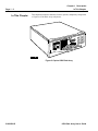
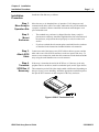
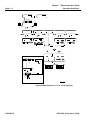
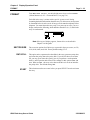
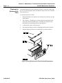
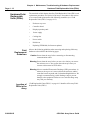
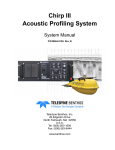
This chapter describes the functions, features, options, and primary components
of Ciprico’s 6500 Disk Array subsystems.
Figure 2 Ciprico 6500 Disk Array
21020690 B
6500 Disk Array User’s Guide
Chapter 1 Description
6500 Disk Array Functions and Application
6500 Disk Array
Functions and
Application
Page 1 - 3
When high-bandwidth software applications require disk performance rates
faster than those provided by single-disk storage systems, Ciprico’s 6500 Disk
Array can provide economical yet powerful performance, redundancy, and
capacity. The 6500 Disk Array provides transfer rates up to 40MB/second.
Each Ciprico 6500 disk array includes an intelligent SCSI/ATA controller, a
full-function display/operation panel, a lockable enclosure with power supply
and cooling fans, and nine ATA drives—eight for data and one for parity.
Available for operation with either single-ended or differential SCSI signal
types, Ciprico 6500 arrays can be easily striped or daisy-chained together to
provide higher capacities.
6500 Disk Array User’s Guide
21020690 B
Chapter 1 Description
Page 1 - 4
Features and Options
Features and
Options
SCSI
Compatibility
Controller
Board
Disk Drives
21020690 B
•
Conforms to SCSI-2 standards.
•
8- or 16-bit data transfers on host interface.
•
Single-ended or differential SCSI interface.
•
Compatible with industry-standard SCSI adapters and drivers, including
all Ciprico SCSI host bus adapters.
SCSI-2 to ATA RAID-3 disk array controller with a 16-bit host SCSI interface
and 9 ATA interfaces.
9 ATA disk drives (8 data, one parity).
Redundancy
Continued operation after failure of a single data drive.
Parallel Disk
Array
Architecture
Ciprico’s 6500 parallel disk array communicates with an initiator (or host) via
the SCSI-2 industry standard interface. The array’s design combines current
drive technology with an advanced controller board, where data is “striped”
across eight drives at once. Byte-striping involves partitioning of data into
bytes, with each byte assigned to a particular drive and all bytes written to the
drives simultaneously. Using this method, transfer rates for read/write
functions are significantly faster than a single disk drive having the same
capacity.
Parity Drive
Improved reliability and data availability are provided by a dedicated parity
drive. As data is striped to the eight data drives, parity data is generated and
stored on the parity drive. Parity information is used to verify data integrity
when reading from the drives, and to regenerate data if a drive should fail and
is replaced. A single drive failure will not degrade overall performance. Use of
6500 Disk Array User’s Guide
Chapter 1 Description
Features and Options
Page 1 - 5
the parity drive also significantly increases data availability—the length of time
before data is lost due to drive failure.
16-Bit Wide
Synchronous
Transfer
The controller has SCSI-P connectors (per the SCSI-2 standard) that permit 16bit wide synchronous data transfers over a single SCSI-P cable on the host
interface. The 6500 is a Wide Ultra SCSI device (SCSI-3), transferring data at
up to 40 MB/second.
Single-Ended
or Differential
Signals
Two methods can be used for sending signals on a SCSI bus—single-ended
and differential. Both are functionally equivalent and transparent to the
software protocol.
Note Single-ended and differential devices must not be combined on the
same SCSI bus. Each 6500 array must be initially ordered as either
single-ended (Model 6511) or differential (Model 6512).
•
Single-Ended Option
The single-ended option permits the use of a single line for each signal.
The line's voltage varies between 0.5 and 3.0 volts DC, with a nominal
switching threshold at about 1.4 VDC. Maximum cumulative length of
single-ended cabling should not exceed 3.0 meters (approximately 10
feet).
•
Differential Option
The differential option consists of two lines designated as a +SIGNAL
and a -SIGNAL. A signal is true when the +SIGNAL is more positive
than the -SIGNAL, and false when the -SIGNAL is more positive than
the +SIGNAL. The differential method is more immune to noise than
the single-ended method, and permits the use of much longer cabling—
up to 25 meters (approximately 82 feet).
Enclosure
Two horizontal mounting options are available—desktop and rack-mount. (For
information on rack-mounting the unit, see documentation included with the
optional rack-mount kit.)
6500 Disk Array User’s Guide
21020690 B
Chapter 1 Description
Page 1 - 6
Primary Components
Primary
Components
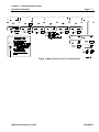
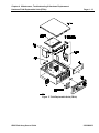
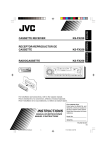
The “Primary Components” diagram on page 1-7 illustrates the 6500 disk array
primary components described below.
Enclosure
The standard 6500 enclosure consists of a front cover and an enclosure cabinet,
built in a desktop configuration. (An optional rack-mounting kit is available.)
Air Filter
An air filter is located between the disk drives and the front of the enclosure.
It must be periodically cleaned to ensure proper air flow.
Controller
Board
The controller board is designed with a multiple local bus architecture. A master
microprocessor commands the board's main processor bus and manages its
operations, including command optimization and processing, failed drive
processing, and high-level drive operations. The master processor
communicates with each drive via an ATA controller circuit. Communications
between the master processor and each drive occur on separate but identical
drive channels.
Display/
Operation
Panel
The operator interface includes a two-line 32-character LCD display and six
control switches.
Disk Drives
9 ATA disk drives (8 data, one parity).
Fans and
Temperature
Sensor
Two fans cool the array. A sensor mounted on the array’s controller board
monitors the temperature inside the enclosure, and triggers an audio alarm if
the temperature rises above the normal operating range. If excessive heat is
detected (critical over-temperature), the array will shut down the drives.
Power Supply
The array’s power supply is switch-selectable for 115 or 230 VAC operation.
A male connector attaches to the power source.
Caution Do not use female power connector.
21020690 B
6500 Disk Array User’s Guide
Chapter 1 Description
Primary Components
Page 1 - 7
Figure 3 Primary Components
6500 Disk Array User’s Guide
21020690 B
Chapter 1 Description
Page 1 - 8
Primary Components
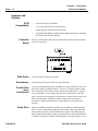
Display/
Operation
Panel
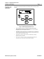
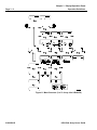
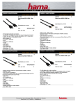
As shown below, the 6500 display/operation panel includes a liquid crystal
display (LCD) and six membrane control switches.
Figure 4 Display/Operation Panel
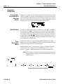
Liquid Crystal Display (LCD)
The 6500 display/operation panel’s LCD indicates real-time array status and
error conditions, and is used to enter a wide range of setup parameters and
operating commands. The LCD displays 2-line by 16-character messages, and
indicates the current position in a tree-structured menu of functions. (See
Chapter 3, Display/Operation Panel.)
RESET Switch
This switch initiates a reset, which returns the array to an initial power-up
condition. In this power-up state, the firmware and SCSI chip are initialized.
Caution The RESET switch initiates a subsystem restart; any activity in
progress will be halted without saving information.
SELECT Switch
The SELECT switch is used to initialize new function selections that appear
on the LCD display.
Navigation Switches (Up, Down, Left, Right)
The four “arrow” switches on the panel are used to step through options in the
tree-structured menu, and to make selections when available. Pressing
SELECT initializes the currently displayed option.
21020690 B
6500 Disk Array User’s Guide
Chapter 1 Description
Rear Panel Switches and Connectors
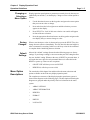
Rear Panel
Switches and
Connectors
Page 1 - 9
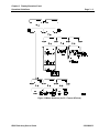
This figure illustrates the rear panel components described below.
Figure 5 Rear Panel—6500 Disk Array
SCSI
Connectors
Two identical 68-pin SCSI-P connectors on the array's controller board enable
connection to a SCSI bus from the host.
Activity LED
A controller board activity LED (located next to the right-most SCSI-P
connector) lights when power is applied to the array during the first part of the
Built-In Self Test (BIST) until the microprocessor extinguishes it. This LED
also flashes on a BIST failure. After completion of BIST, it lights whenever
the controller board is busy with a SCSI command.
Power ON/
OFF Switch
The array’s power ON/OFF switch is located on the rear panel next to the power
supply.
Power Cord
Connectors
On the power supply, a male connector attaches to the power source.
Power Voltage
Selection
Switch
Caution Do not use female power connector.
A switch located between the two power cord connectors on the power supply
is used to select 115 or 230 VAC operation for the array.
6500 Disk Array User’s Guide
21020690 B
2
Installation
Chapter 2 Installation
Page 2 - 2
In This Chapter
In This Chapter
This chapter describes a typical installation of the 6500 Disk Array subsystem.
Note Instructions for attaching a rack-mount kit to the enclosure are
included with the rack-mount kit.
21020690 B
6500 Disk Array User’s Guide
Chapter 2 Installation
Installation Procedure
Installation
Procedure
Step 1.
Move Array to
Operation Site
Step 2.
Mount
Enclosure
Page 2 - 3
Install the 6500 disk array as follows:
Move the array to its intended place of operation. Verify that power and
communication cables will be accessible, and that the array will be installed in
a properly ventilated, climate-controlled environment with adequate work
space around the unit.
•
The standard array enclosure is shipped from the factory ready for
placement on a desktop. Attach the supplied rubber feet to the bottom of
the enclosure, and position the unit properly on a desk or other work
surface.
•
If you have ordered the rack-mount option, attach the kit to the enclosure
as described in the instructions included with the rack-mount kit.
Step 3.
Attach SCSI
Cable
Connect one end of the host-to-array SCSI cable to the host system, and the
other end to one of the SCSI-P connectors on the rear panel of the array. To
ensure a secure connection, attach the cable connectors to both the host and the
array using the small thumbscrews on each connector.
Step 4.
Terminate
SCSI Bus, if
Necessary
If the array is located at the end of the SCSI bus, or if the array is the only
peripheral device on the bus, install a termination pack (see the figure below.)
The termination pack will be either single-ended or differential, depending on
the type of array you are installing. Attach the appropriate termination pack to
the open SCSI-P connector on the rear panel of the array enclosure.
Figure 6 SCSI-P Termination Pack
6500 Disk Array User’s Guide
21020690 B
Chapter 2 Installation
Page 2 - 4
Installation Procedure
Step 5.
Set Array
Input Voltage
Switch
Before you connect the array’s power cord to an AC outlet, you must set the
array power supply’s input voltage selection switch to the proper position: the
“115” setting for 100-120 VAC, or the “230” setting for 200-240 VAC.
The power supply’s input voltage selection switch is located between the two
power cord connectors on the rear panel of the array.
Caution If the input voltage selection switch is not in the correct position,
the array power supply will be damaged when power is applied.
Step 6.
Attach Power
Cord
First, verify that the array power ON/OFF switch on the rear panel of the
enclosure is in the OFF position. Then plug the power cord into the appropriate
connector on the rear panel of the array. Plug the other end of the power cable
into the power source.
Caution The standard power cord provided with the array is for use in the
United States and Canada. If necessary, replace the power cord
with one that meets local safety and electrical standards.
Step 7.
Power Up the
Array
Step 8.
Check Array
Status
Move the power switch on the rear panel of the array enclosure to the ON
position.
Observe the display/operation panel for the following start-up displays and
status indications.
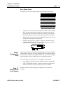
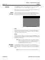
Drive Status
At array reset or power-up, the display/operation panel will cycle through a
series of displays that show the status of each drive in the array.
Drives in the array are numbered from right to left, with drive number 1
representing the parity drive and drives 2-9 representing the eight data drives.
9876-5432-1
(Drive 1 = Parity Drive)
21020690 B
6500 Disk Array User’s Guide
Chapter 2 Installation
Installation Procedure
Page 2 - 5
Drive Status Codes
The following codes on the display/operation panel indicate drive status:
Code
O
S
G
T
R
U
X
?
F
Drive Status
OFF
Spinning
Good (Tested OK)
Testing
Ready
Unformatted for Array
Out of Order
Unknown Status
Failed
Table 1: Drive Status Codes
Step 9.
Configure the
Array
•
At array reset or power-up, a Built-In Self-Test (BIST) will run. During
BIST, the drive status display reflects the test stage that each drive is
passing through. Under normal conditions, each drive passes through
stages OFF, Spinning, Testing, Good, and then Ready, as listed above.
•
When all drives are in the same state, an English-language status message
will appear on the display/operation panel.
•
During the spin-up process, all drives in the array reach their normal
operating speed and each drive is tested. When testing and spin-up are
complete, the 67$786 2. message appears.
Ciprico ships 6500 arrays with default settings designed to suit most operating
environments. If necessary, you may reconfigure the array using the display/
operation panel. (Chapter 3 in this guide describes how you can use the display/
operation panel to verify or change the array’s operating parameters.)
In most situations, you will only have to reconfigure two parameters:
Step 10.
Power Up the
Host System
•
Array SCSI ID—Each device on the SCSI bus must have a unique ID.
•
UNIT ATTENTION reporting—SCSI drivers in some systems do not
handle this parameter correctly and it may have to be disabled.
When the 6500 array has been properly configured, power up the host
computer.
6500 Disk Array User’s Guide
21020690 B
3
Display/Operation Panel
Chapter 3 Display/Operation Panel
Page 3 - 2
In This Chapter
21020690 B
In This Chapter
This chapter describes the options and functions available with the 6500 Disk
Array display/operation panel. The panel is used to observe current array status,
change operating parameters, and manually control the array.
6500 Disk Array User’s Guide
Chapter 3 Display/Operation Panel
Controls and Indicators
Controls and
Indicators
Page 3 - 3
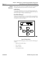
The display/operation panel includes an LCD display and six membrane control
switches.
Figure 7 6500 Display/Operation Panel
•
The LCD displays 2-line by 16-character messages that include
directional arrows showing you which switches to use for navigation
through the menu or for function selection.
•
The RESET switch returns the array to an initial power-up condition in
which the firmware and SCSI chip are initialized. Any in-progress array
activity will be halted without saving.
•
The SELECT switch is used to activate or initialize the currently
displayed option or function.
•
Four “arrow” switches are used to step through options in the treestructured menu, and to make selections when available.
6500 Disk Array User’s Guide
21020690 B
Chapter 3 Display/Operation Panel
Page 3 - 4
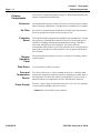
Operation Guidelines
Operation
Guidelines
Array PowerUp and Built-In
Self-Test
(BIST)
When the array is powered up, the display/operation panel turns on and a BuiltIn Self-Test (BIST) is executed. Text descriptions for most of the tests briefly
appear on the panel as the tests are performed. This process takes approximately
10 seconds, after which the drives in the array are started and begin to spin up.
When this process is finished, the display should look like this:
Initial Display
Normally, the initial display appears as shown above: 21 /,1( (or assigned
array name) 67$786 2.. If a failure occurs with any of the drives in the
array, however, the bottom line will show the status of each of the nine drives
in descending order, from left to right. For example, an array with a failed drive
6 would display: 555)55555 (data drives 9876-5432 and parity drive 1).
The down arrow at the right end of the top line indicates that menu selections
are available only in that direction.
TreeStructured
Menu
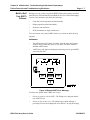
The first level in the tree (below the initial display, entered by pressing the
down arrow once) is the )81&7,21 6(/(&7 level, which divides the menu
tree into the categories shown in the figure below.
“Menu Structure (1 of 5—Array Options)” on page 3-6 illustrates the entire
menu structure. The “Display Key” on “Menu Structure (2 of 5—Array
Options)” on page 3-7 explains which arrows are enabled for each menu.
Note See the Display/Operation Panel Quick Reference included with
the equipment for an abbreviated version of the diagrams on the
following pages.
Figure 8 Function Selection Options
21020690 B
6500 Disk Array User’s Guide
Chapter 3 Display/Operation Panel
Operation Guidelines
Changing or
Selecting a
Menu Option
Page 3 - 5
Display/operation panel options or parameters currently in use by the array are
identified by an asterisk (*) on the display. Change or select a menu option as
follows:
1.
Use the directional arrows on the keypad to navigate to the menu option
that you want to select or change.
2.
Press and release the left or right arrow until the selection you want
appears on the display.
3.
Press SELECT to “lock in” this new selection. An asterisk will appear
in front of the new selection.
4.
Press the appropriate directional arrows on the keypad to navigate to the
next display that you want to change or select.
Saving
Changes
When a new function or value is chosen and you press the SELECT key, the
change becomes effective immediately. The only time this does not happen is
when a command is executing. In this case, the array waits for the command
to complete before initializing the new selection.
Default
Settings
Most of the “default” settings discussed on the following pages are factory
settings. If you change a setting, be sure to note that your new setting becomes
the new “default” setting. Whenever the array is RESET or powered down, it
will retain the same value for each parameter that was in effect before the
RESET or power-up. There are two exceptions:
Menu Option
Descriptions
•
ON/OFF LINE will always revert to ON LINE
•
REBUILD% will always revert to 99%
The remainder of this chapter lists and describes the menu selections and
options available on the 6500 array display/operation panel.
The complete tree structure of the display/operation panel menu system is
shown in the diagrams on the following pages. The descriptions following the
diagrams are grouped under the primary first-level selections in the menu
system:
•
ARRAY OPTIONS
•
ARRAY INFORMATION
•
REBUILD
•
FORMAT
•
DRIVES
•
LOG PAGES
6500 Disk Array User’s Guide
21020690 B
Chapter 3 Display/Operation Panel
Page 3 - 6
Operation Guidelines
Figure 9 Menu Structure (1 of 5—Array Options)
21020690 B
6500 Disk Array User’s Guide
Chapter 3 Display/Operation Panel
Operation Guidelines
Page 3 - 7
Figure 10 Menu Structure (2 of 5—Array Options)
6500 Disk Array User’s Guide
21020690 B
Chapter 3 Display/Operation Panel
Page 3 - 8
Operation Guidelines
Figure 11 Menu Structure (3 of 5—Array Info & Rebuild)
21020690 B
6500 Disk Array User’s Guide
Chapter 3 Display/Operation Panel
Operation Guidelines
Page 3 - 9
Figure 12 Menu Structure (4 of 5—Format & Drives)
6500 Disk Array User’s Guide
21020690 B
Chapter 3 Display/Operation Panel
Page 3 - 10
Operation Guidelines
Figure 13 Menu Structure (5 of 5—Log Pages)
21020690 B
6500 Disk Array User’s Guide
Chapter 3 Display/Operation Panel
ARRAY OPTIONS
ARRAY
OPTIONS
Page 3 - 11
From )81&7,21 6(/(&7 , use the left/right arrow keys to select $55$<
237,216 (see “Menu Structure (1 of 5—Array Options)” on page 3-6 and
“Menu Structure (2 of 5—Array Options)” on page 3-7). Array options include:
OPTION
DEFAULT SETTING
ON
LINE (or assigned array
ON/OFF LINE
name)
SCSI ID
0
PASSWORD
(none)
UNIT ATTENTION
ON
WRITE PROTECT
OFF
ALARM
ON
SET DEFAULTS
NO
RPT AS RECOVER
OFF
TEMP WARNING
45 degrees C
TEMP CRITICAL
ON
AUTO MEGOMETER
OFF
ARRAY NAME
(blank)
Table 2: Array Options
ON/OFF LINE
When ON LINE, the array is ready to receive commands from the system it is
connected to.Take the array OFF LINE if you want to prevent user access while
performing a rebuild or other maintenance.
SCSI ID
Each device on the SCSI bus must have a unique ID. This option allows you
to set the array's SCSI ID from 0 to 15. This is typically set to 0 unless multiple
arrays are daisy-chained together or the ID of the host SCSI port is zero.
6500 Disk Array User’s Guide
21020690 B
Chapter 3 Display/Operation Panel
Page 3 - 12
ARRAY OPTIONS
PASSWORD
The password option allows you to set or clear the array's password protection
feature. When set, the password is a user-entered series of four display/
operation panel keystrokes—any key can be used except the RESET key.
Enter a New Password
Enter a new password as follows:
21020690 B
1.
Press the down arrow, then press the right or left arrow until
)81&7,21 6(/(&7$55$< 237,216 appears.
2.
Press the down arrow.
3.
Press the right or left arrow until 3$66:25' appears.
4.
Press the down arrow to view the (17(5 3$66:25' menu. If &/($5
3$66:25' is displayed, press the right key once to show (17(5
3$66:25'.
5.
Press the down arrow.
6.
Press four keypad keys in sequence (do not use the RESET key in this
sequence), and be sure to note the keys you enter (see example at left:
left, left, down, up). This four-key sequence will be your new password.
As each password key is pressed, an asterisk is displayed in the panel.
When the fourth key is pressed, 3$66:25' 6(7 is displayed.
6500 Disk Array User’s Guide
Chapter 3 Display/Operation Panel
ARRAY OPTIONS
Page 3 - 13
Clear Password
Clear a password as follows:
1.
Press the down arrow, then press the right or left arrows until
)81&7,21 6(/(&7$55$< 237,216 is displayed.
2.
Press the down arrow.
3.
Press the right or left arrows until the 3$66:25' menu is displayed.
4.
Press the down arrow to view the &/($5 3$66:25' menu. If (17(5
3$66:25' is displayed, press the right key once to show &/($5
3$66:25'
5.
Press the down arrow.
6.
Press the right arrow once to display <(6, then press SELECT. The
panel immediately displays &/($5(', and password protection is
cleared from the array.
UNIT
ATTENTION
If your system cannot handle SCSI bus errors reported with a SCSI UNIT
ATTENTION signal, use this option to keep the array from doing so. 81,7
$77(17,21 is typically set to 21. Setting 81,7 $77(17,21 to 2)) will
result in some error messages, such as Drive Failure and Reset, not being
reported over the SCSI bus. When active, an alarm will sound and a message
will display.
WRITE
PROTECT
Setting :5,7( 3527(&7 to 21 prevents any data from being written to the
array. This is typically set to 2)).
ALARM
This menu allows turning the audible alarm on and off. The audible alarm turns
on when any of the following conditions occur in the array:
•
Disk drive fails
•
Over-temperature sensor detects excessive heat
To silence the alarm temporarily when it is active, press any key to turn off the
alarm. The $/$50 setting is typically set to 21.
6500 Disk Array User’s Guide
21020690 B
Chapter 3 Display/Operation Panel
Page 3 - 14
ARRAY OPTIONS
SET
DEFAULTS
Setting the 6(7 '()$8/76 to <(6 returns the array to its factory default
settings for :5,7( 3527(&7 81,7 $77(17,21 $/$50 537 $6
5(&29(5 $55$< 1$0( 7(03 :$51,1* 7(03 &5,7,&$/ , and
0(*20(7(5. The default for this option is 12.
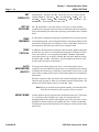
RPT AS
RECOVER
537 $6 5(&29(5 is set to 21 when it is necessary for Unit Attention
TEMP
WARNING
Use this option to change the temperature at which the array will issue an alarm
and warning display (:), the warning threshold for overheating conditions. This
temperature warning can be set in degrees Celsius or Fahrenheit, and refers to
the temperature detected by the sensor on the controller board.
TEMP
CRITICAL
In addition to the temperature warning (:), there is another, higher temperature
at which the array’s drives are automatically shut down (50 degrees Celsius).
This is the critical (&) over-temperature threshold. The 7(03 &5,7,&$/
menu option allows you to enable or disable this automatic shutdown feature.
Positions are 21 and 2)). (When 2)), the unit attention and alarm are still
issued but the array does not shut down.)
AUTO
MEGOMETER
(ON/OFF)
The megometer feature displays the array’s current data transfer rate in
megabytes per second. Because transfer rates vary considerably from moment
to moment, the rate shown is actually the average transfer rate for a two-second
period. This averaging yields a more accurate representation of overall transfer
performance.
conditions to be reported as Recovered Errors rather than with a Unit Attention.
This is determined by the needs of the operating system and the driver. Default
is 2)).
When the megometer is 21, the transfer rate is the default display unless some
other message preempts it. When you switch the megometer display 2)), the
transfer rate will not display until you switch it 21 again.
Note When you select the auto megometer display, it will not take effect
until the next subsystem reset or power cycle has occurred.
ARRAY NAME
21020690 B
Use this option to specify a logical name or designator for the array. This feature
is a convenience where multiple array units are used and need to be
distinguished from one another with assigned names. The array name is a userdefinable 14-character string, and is displayed on line 1 in place of 21 /,1(.
The displayed name will be replaced by error messages or menu selection titles
when active.
6500 Disk Array User’s Guide
Chapter 3 Display/Operation Panel
ARRAY INFORMATION
ARRAY
INFORMATION
Page 3 - 15
From )81&7,21 6(/(&7 , use the left/right arrow keys to select $55$<
,1)250$7,21 (see “Menu Structure (3 of 5—Array Info & Rebuild)” on page
3-8). These display-only selections let you view the following array
information:
),50:$5(
7(03(5$785( 6(16256
&$3$&,7<
,1,7,$725 ,1)250$7,21
0(*O0(7(5
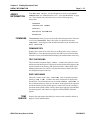
FIRMWARE
The ),50:$5( menu gives you access to three firmware parameters: firmware
revision level (),50:$5( 5(9 ); the results of a checksum test (7(67
&+(&.6806); and a display of the hexadecimal tallies of the checksum test
(',63 &+(&.6806 ).
FIRMWARE REV
Displays the revision level of the firmware residing in the array’s firmware
PROM device. Two submenus display the date and time associated with the
firmware revision, and a third submenu displays the model number of the array.
TEST CHECKSUMS
This item and its submenu display, as 3$66 or )$,/, the results of a test in
which expected checksums are compared to actual calculated checksums of the
current contents of the Primary (PR) firmware buffers, and the BIST buffer.
Matching checksums for a buffer verify that the contents of that buffer have
not changed and it passes the test.
DISP CHECKSUMS
This item is similar to the 7(67 &+(&.6806 item except that, instead of
showing a 3$66 or )$,/ condition, the actual checksums are displayed in
hexadecimal. Two submenu items are associated with ',63 &+(&.6806 . In
the second submenu item, there are four entries: at the upper left, the expected
checksum from the primary buffer appears; at the lower left, the calculated
checksum for the primary buffer is shown; at the upper right, the expected BIST
checksum appears; and at the lower right, the calculated BIST checksum
appears.
TEMP
SENSOR
Displays the temperature detected by the sensor (on the controller board) in
degrees Celsius and Fahrenheit.
6500 Disk Array User’s Guide
21020690 B
Chapter 3 Display/Operation Panel
Page 3 - 16
ARRAY INFORMATION
CAPACITY
Displays the logical block number of the last data block in the array. A value
followed by ' indicates a decimal number; a value followed by + indicates a
hex number.
To calculate the capacity of the array, add one to the number displayed. For
example, a display with ' in an array formatted with 512 as the
sector size indicates that the array's capacity is 4,207,837 blocks of 512 bytes
each.
INITIATOR
INFO
A SCSI-2 bus can have up to 16 devices attached to it, with some devices acting
as initiators of SCSI commands, and some acting as targets. The array is always
a target.
The SCSI protocol allows targets and initiators to negotiate the width of the
bus to be used when transferring data, the transfer rate, and also whether the
transfer will be synchronous or asynchronous. This information is stored by the
array for each initiator on the SCSI bus under Array Information.
P is the Transfer Period
O is the Synchronous Offset
W indicates that a wide 16-bit bus will be used
N indicates that a narrow 8-bit bus will be used
To determine the Transfer Rate from the Transfer Period:
1.
Translate the hexadecimal Transfer Period into decimal. For example,
19H equals decimal 25.
2.
Multiply the decimal value by 4 to get the Transfer Period in
nanoseconds (25 x 4 = 100).
3.
Take the reciprocal of this value to get the Transfer Rate in Megahertz
(1/100-9 = 10 Megahertz).
4.
Multiply by the bus width (1 or 2 bytes) to get the bus burst transfer
rate, e.g., 10 MHz x 2 bytes wide = 20MB/second.
Note Because the 6510 employs Wide Ultra SCSI technology, the SCSI
specification requires a slight variation to the computations above.
Wide Ultra SCSI technology is designated as 0CH or decimal 12,
when in fact it is slightly longer at 12.5. When the designated
period is multiplied by 4 to get the Transfer Period in nanoseconds,
the result is 48. In reality it is 50, which is the value whose
reciprocal 1/50 nanoseconds equals 20 Megahertz (20MB/
second).
21020690 B
6500 Disk Array User’s Guide
Chapter 3 Display/Operation Panel
ARRAY INFORMATION
Page 3 - 17
The Synchronous Offset represents the number of bytes a SCSI ACK signal
may lag a REQ signal. 16 (10H) is the maximum Offset allowed. Although
communications allow up to a 16 byte offset, each byte is always
acknowledged. For additional information, see the SCSI-2 specification.
MEGoMETER
(DISPLAY)
The 0(*O0(7(5 displays the transfer rate in megabytes per second. Because
transfer rates vary considerably moment to moment, the rate shown is actually
the average of transfer rates for a two-second period. This averaging yields a
more accurate representation of the overall transfer performance.
6500 Disk Array User’s Guide
21020690 B
Chapter 3 Display/Operation Panel
Page 3 - 18
REBUILD
From )81&7,21 6(/(&7, use the left/right arrow keys to select the following
5(%8,/' functions (see “Menu Structure (3 of 5—Array Info & Rebuild)” on
REBUILD
page 3-8). Use the display/operation panel rebuild options listed below as
described in Chapter 4 of this guide.
Caution If a disk in the array fails, replace the drive and perform a rebuild
as soon as possible. A rebuild can be performed without taking the
array off-line. See Chapter 4 for drive replacement and rebuild
instructions.
REBUILD
DATA
Your selection for the 5(%8,/' '$7$ parameter determines whether or not
the data from the failed drive will be reconstructed on the new replacement disk
drive. 21 means the data will be rebuilt; 2)) means the data will not be rebuilt.
Caution '$7$ 21 should always be selected for a data rebuild. Rebuilding
with this selection 2)) may result in data corruption and/or interdrive parity errors.
21020690 B
REBUILD%
This menu selection allows you to select the percentage of processing time the
array will dedicate to the rebuilding process: , or . The lower
the percentage, the longer the rebuild will take. The default setting is .
START
This selection must be set to <(6 before you press SELECT to rebuild a drive.
6500 Disk Array User’s Guide
Chapter 3 Display/Operation Panel
FORMAT
Page 3 - 19
From )81&7,21 6(/(&7 , use the left/right arrow keys to select )250$7
(“Menu Structure (4 of 5—Format & Drives)” on page 3-9).
FORMAT
Each disk in the array is written with a special “system sector” during
formatting that holds information about the array. For this reason, an array must
be formatted before it can be used. All arrays are formatted completely before
shipment. You must format the array only if, on power-up or reset, you see a
display similar to the following, which indicates that drives 9, 6, 5, and 4 in the
array are unformatted.
Note If this type of display appears, format drives as described in
Chapter 4 of this guide.
SECTOR SIZE
The sector size options for 6500 arrays, expressed in bytes per sector, are 512,
1024, 2048, 4096, and 8192. Factory default setting is 512.
DATA FILL
This option writes a pattern to the data disks in the array, generates parity data,
and writes the parity data to the parity disk. If you do not choose to use data
fill, you may get an inter-drive parity error if you perform a read operation
before a write operation after format. The settings for this option are 21 and
2)). When set to 21, the array writes data to the drives in order to initialize
the parity drive. The default setting is 21.
START
This selection must be set to <(6 before you press SELECT in order to format
the array.
6500 Disk Array User’s Guide
21020690 B
Chapter 3 Display/Operation Panel
Page 3 - 20
DRIVES
From )81&7,21 6(/(&7 , use the left/right arrow keys to select '5,9(6
(see “Menu Structure (4 of 5—Format & Drives)” on page 3-9).
DRIVES
These menus let you view the current drive status, disable a disk drive, and
view information on the drive's model number.
DRIVE
STATUS
The read-only '5,9( 67$786 option typically displays 5($'< for each
drive. Any of the drive status options listed below could be displayed, however.
The status for any installed drive can be viewed with this selection.
Code
O
S
G
T
R
U
X
?
F
Drive Status
OFF
Spinning
Good (Tested OK)
Testing
Ready
Unformatted for Array
Out of Order
Unknown Status
Failed
Table 3: Drive Status Options
ASQ
This menu selection typically displays . A non-zero number indicates a
failed drive and an ASQ code is associated with the failure. See note below.
(This menu selection is display-only.)
XTRA
This menu selection is display-only, and typically displays . A nonzero number indicates a failed drive and an ASQ XTRA code is associated with
the failure. See note below.
Note In this case, ASQ (Additional Sense Code Qualifier) and ASQ
XTRA codes apply to a drive failure condition. These codes are
not easily interpreted. Contact your service provider for an
explanation if these codes are non-zero.
DISABLE
DRIVE
Use this option to shut down any drive in the array for maintenance or
replacement. When you press the SELECT key, the array will spin down the
drive. This function is not available if another drive is currently disabled or
failed.
Note See Chapter 4 for drive replacement and rebuild instructions.
21020690 B
6500 Disk Array User’s Guide
Chapter 3 Display/Operation Panel
DRIVES
DRIVE INFO
Page 3 - 21
The '5,9( ,1)2 menu provides access to two submenus which describe the
model number of each drive used in the array and the firmware revision of each
drive.
Press the down arrow key to advance to the first information menu.
DRIVE n MODEL
This option displays the model number of the drive. Use the right and left arrow
keys to move to the next drive in the array.
DRIVE n REV
This option displays the drive's firmware revision. Use the right and left arrow
keys to move to the next drive in the array.
6500 Disk Array User’s Guide
21020690 B
Chapter 3 Display/Operation Panel
Page 3 - 22
LOG PAGES
LOG PAGES
From F81&7,21 6(/(&7 , use the left/right arrow keys to select /2* 3$*(6
(see “Menu Structure (5 of 5—Log Pages)” on page 3-10).
These selections provide access to drive error information contained in SCSI
log pages. Three menus in this category ((5525 &2817(56 '5,9(
(55256, and '5,9( )$,/85(6) give access to “pages” of SCSI log entries.
Three additional items ((1$%/( /2* 5(6(7 /2* , and 6(7
7+5(6+2/'6) are commands that allow you to manipulate or control these
internal log pages. These commands affect all log pages and cannot be applied
deferentially to individual log pages.
ERROR
COUNTERS
For each drive, this menu gives access to a tally of recovered errors and a tally
of medium errors. Medium errors are non-recoverable errors related to flaws
in the drive’s memory medium material. The (5525 &2817(56 menu item
relates to SCSI log page number 3.
DRV n ERR COUNT / RECOVERED
Displays a 5-digit tally of recovered errors for each drive (with a maximum
tally of 65,535 errors). “n” is the drive number (n=1-9).
DRV n ERR COUNT / MEDIUM
Displays a 5-digit tally of medium errors for each drive (with a maximum tally
of 65,535 errors). “n” is the drive number (n=1-9).
DRIVE
ERRORS
This item gives access to the error entry for each recorded drive error
occurrence. 40 error entries can be stored. For each error occurrence, an error
entry number is assigned. The error entry identifies the drive on which the error
occurred, gives SCSI codes that describe the error, and tells the location on the
drive (logical block address) at which the error occurred, if applicable.
The sense key code gives the primary description of the error. ASC and ASQ
codes give additional information about the error entry, but for some error
entries, these two codes will not be applicable. Because the 6500 arrays are
equipped with ATA drives, they produce ATA error codes. These are
translated, on the controller board, into SCSI codes to maintain compatibility
with arrays equipped with SCSI drives. The '5,9( (55256 item relates to
SCSI log page number 4.
If no errors have been recorded, the display for this menu item will read '5,9(
(55256 /,67 (037<.
ENTRY k / DRIVE n
This item gives you access to error entries by entry number and tells you the
drive on which each error occurred (k=1-40, n=1-9).
21020690 B
6500 Disk Array User’s Guide
Chapter 3 Display/Operation Panel
LOG PAGES
Page 3 - 23
ENTRY k / SENSE KEY: yyH
This item gives you the two-digit hexadecimal sense key code for the
error entry. Every error will have a sense key code. The sense keys report
generic categories of error and exception conditions. Initiators typically use
sense keys for high-level error recovery procedures.
ENTRY k / ASC: yyH
This item displays the two-digit hexadecimal code for the ASC code that applies
to the error entry. (ASC = Additional Sense Code.)
ENTRY k / ASQ: yyH
This item displays the two-digit hexadecimal code for the ASQ code that
applies to the error entry. (ASQ = Additional Sense Code Qualifier.)
ENTRY k / LBA 12345678H
This item specifies the Logical Block Address on the drive at which the error
occurred, if applicable. (Some errors are not associated with a specific block
location on the drive.) The address is an 8-digit hexadecimal number.
DRIVE
FAILURES
This item gives access to the entry for each recorded drive failure occurrence.
Records for the last 16 drive failures can be stored in this log. For each failure
occurrence, a failure entry number is assigned. The failure entry identifies the
drive on which the failure occurred and gives two kinds of SCSI codes that
describe the failure. The first is a two-digit hexadecimal ASQ code (Additional
Sense Code Qualifier); the second is an eight-digit hexadecimal EXTRA code.
ASQ is a standard category of SCSI error codes; EXTRA codes are diagnostic
codes unique to Ciprico. The DRIVE FAILURES item relates to SCSI log page
number 5.
If no failures have been recorded, the display for this menu item will read
'5,9( )$,/85(6 /,67 (037<.
ENTRY j / DRIVE n
This item gives you access to drive failure entries by entry number, and tells
you the drive on which each failure occurred. (j=1-16, n=1-9)
ENTRY j / ASQ: zzH - This item gives you the two-digit hexadecimal code
of the ASQ type that applies to the drive failure occurrence. (ASQ = Additional
Sense Code Qualifier.)
ENTRY j / EXTRA: ggggggggH - This item gives you the eight-digit
hexadecimal code of the EXTRA type that applies to the error entry.
6500 Disk Array User’s Guide
21020690 B
Chapter 3 Display/Operation Panel
Page 3 - 24
LOG PAGES
ENABLE LOG
This item lets you enable or disable the logging function by choosing 21 or
2)). The factory default setting is 21. If you cycle power, the (1$%/( /2*
item will come up in the condition it was in when you turned off the array.
RESET LOG
This command sets all log counters back to zero and sets functions to their
default conditions. When you invoke this command, all entries for drive errors
and drive failures will be erased. The default setting is 12. To implement this
command, use the left arrow key to select <(6, then press SELECT. After a
reset, this parameter reverts to 12.
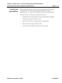
SET
THRESHOLDS
This item allows you to view and set thresholds for the number of errors at
which the array will automatically shut down a drive. There are separate
thresholds for recovered errors and medium errors, but each of these thresholds
applies to all nine drives. Factory defaults for both recovered and medium errors
are zero, which indicates that the shutdown-on-threshold feature is disabled.
SET THRESHOLDS / RECOVERD
Gives access to view and set the threshold for triggering of automatic
shutdowns because of recovered errors.
RECOVERED / wwwww ERRS
To set the threshold for recovered errors, press the down arrow. This causes
the cursor to flash over the least significant digit of the 5-digit threshold
(maximum value = 65,535). To increment the threshold setting, press the right
arrow key; to decrement it, press the left arrow key. Press the down arrow again
to move to the next digit. When the desired threshold is set, press SELECT.
SET THRESHOLDS / MEDIUM
Gives access to view and set the threshold for triggering of automatic
shutdowns because of non-recoverable medium errors.
RECOVERED / vvvvv ERRS
To set the threshold for medium errors, press the down arrow. This causes the
cursor to flash over the least significant digit of the 5-digit threshold (maximum
value = 65,535). To increment the threshold setting, press the right arrow key;
to decrement it, press the left arrow key. Press the down arrow again to move
to the next digit. When the desired threshold is set, press SELECT.
21020690 B
6500 Disk Array User’s Guide
4
Maintenance,
Troubleshooting &
Hardware Replacement
Chapter 4 Maintenance, Troubleshooting & Hardware Replacement
Page 4 - 2
In This Chapter
21020690 B
In This Chapter
This chapter contains information you will need for Ciprico 6500 Disk Array
maintenance, troubleshooting, and hardware replacement:
•
Periodic maintenance guidelines
•
Failure detection and troubleshooting guidelines
•
Hardware field-replaceable units (FRUs)
6500 Disk Array User’s Guide
Chapter 4 Maintenance, Troubleshooting & Hardware Replacement
Periodic Maintenance Guidelines
Periodic
Maintenance
Guidelines
Checking
Enclosure
Cooling Fan
Operation
Page 4 - 3
Under normal conditions, the 6500 array requires minimal periodic
maintenance. Preventive maintenance consists of periodically checking the
operation of cooling fans and cleaning the enclosure’s air filter.
Periodically inspect the rear panel of the array enclosure to verify that the two
enclosure cooling fans are operating properly. Make sure that both fans are
spinning, and check for any unusual bearing noises.
If fan operation does not seem normal, first verify that the cooling fans are
receiving DC power from the power supply.
If you need to replace one or both enclosure cooling fans, refer to the fan
replacement procedures in this chapter.
Checking
Power Supply
Cooling Fan
Operation
Periodically check the internal fan on the array’s power supply to verify that it
is operating properly.
6500 Disk Array User’s Guide
21020690 B
Chapter 4 Maintenance, Troubleshooting & Hardware Replacement
Page 4 - 4
Periodic Maintenance Guidelines
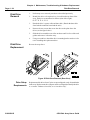
Cleaning the
Enclosure Air
Filter
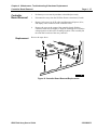
To maintain optimum air flow in the array enclosure, clean the air filter twice
per year, or more frequently if the environment is dusty or the array is installed
in an exposed area.
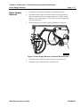
To clean the enclosure air filter:
1.
Remove the front cover and top cover from the array enclosure (see the
figure below).
2.
The air filter is a flexible piece of foam material located between the
front of the enclosure and the drives. Carefully flex and remove the
material from its mounting position in the enclosure.
3.
Clean the filter with a vacuum cleaner.
4.
Insert the clean filter back into its mounting position in the enclosure.
5.
Replace and secure the top cover and front cover on the enclosure.
Figure 14 Array Enclosure Air Filter Removal/Replacement
21020690 B
6500 Disk Array User’s Guide
Chapter 4 Maintenance, Troubleshooting & Hardware Replacement
Failure Detection and Troubleshoot-ing Guidelines
Failure
Detection and
Troubleshooting Guidelines
Page 4 - 5
These topics are discussed on the following pages:
•
Failure indicators
•
Built-In Self Test (BIST) failures
•
Drive test failures
•
Disk drive failures
•
Over-temperature failures
•
Troubleshooting guidelines
6500 Disk Array User’s Guide
21020690 B
Chapter 4 Maintenance, Troubleshooting & Hardware Replacement
Page 4 - 6
Failure Detection and Troubleshoot-ing Guidelines
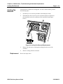
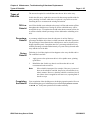
Failure
Indicators
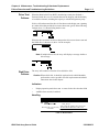
When a failure occurs on the array, an audible alarm sounds, if enabled, and
the display/operation panel reports the nature of the failure condition.
Audible Alarm
To turn off the audible alarm, press any key on the display/operation panel
(except RESET). Write down any error codes that are displayed. Pressing a key
will cause the display to change to a different message.
Error/Failure Messages
The display/operation panel shows error codes and failure messages that direct
you to the source of failure. If there are no failures, the panel will read 21 /,1(
(or assigned array name) 67$786 2..
Figure 15 Display Status
As described on the following pages, you may encounter the following types
of failures:
21020690 B
•
Built-In Self-Test (BIST) failures
•
Drive test failures
•
Disk drive failures
•
Over-temperature failures
6500 Disk Array User’s Guide
Chapter 4 Maintenance, Troubleshooting & Hardware Replacement
Failure Detection and Troubleshoot-ing Guidelines
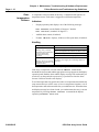
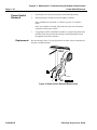
Built-In Self
Test (BIST)
Failures
Page 4 - 7
During power-up, or after you push the RESET button on the display/operation
panel, the array will automatically run a Built-In-Self-Test. This test thoroughly
exercises array hardware and checks the following:
•
Controller board components and functionality
•
Display/operation panel functionality
•
Firmware code checksum
•
SCSI termination for single-ended arrays
You can reset the array and run BIST whenever you want to check the array
internals.
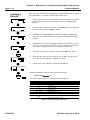
Indicators
•
The audible alarm will sound, if enabled. After the alarm has begun to
sound, it will go silent after any key is pressed. The alarm cannot be
disabled in BIST mode.
•
A BIST error will appear on the display/operation panel. A typical BIST
error looks like this:
Figure 16 Sample BIST Error Message
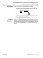
You have two options when a BIST error occurs:
•
Choose to continue with the BIST—The failing test is skipped, and the
rest of BIST is run.
•
Choose to loop on the error—The failing test is retried infinitely; a
percentage of error will be displayed. Press SELECT to stop the looping.
6500 Disk Array User’s Guide
21020690 B
Chapter 4 Maintenance, Troubleshooting & Hardware Replacement
Page 4 - 8
Failure Detection and Troubleshoot-ing Guidelines
To choose the Continue response to a BIST error, press the left arrow key.
To choose the Loop response to a BIST error, press the right arrow key.
When your option, either /223 or &217, is displayed, press SELECT to
implement that option. /223 indicates that the array will repeat that particular
test if SELECT is pressed. &217 skips the failed test and continues with the
other BIST tests when you press SELECT.
Handling
If you see this
6&6, %86 ,6 +(/'
:$,7,1*
8 TGST
(RROR Meaning: External SCSI bus error.
Check or replace this
Check SCSI bus termination (single-ended arrays
only). Terminator may not be present, may be
broken, or the wrong kind.
Disconnect the array SCSI cable from Host and
reset the array. If BIST now passes, the problem
lies in the host system SCSI interface. Check the
host SCSI adapter.
Verify Termpower. Check that the TPR jumper is
installed on the array controller board.
Replace the array controller board.
Note
If a differential controller board is unterminated,
the BIST will complete without reporting the
unterminated condition. During subsequent
operation, various errors, apparently not related to
the termination, will occur. In the event of
unspecified error conditions, first verify that the
differential termination is in place.
TGST NCMG!
(5525 XX XX
Replace array controller board.
Table 4: BIST Troubleshooting
21020690 B
6500 Disk Array User’s Guide
Chapter 4 Maintenance, Troubleshooting & Hardware Replacement
Failure Detection and Troubleshoot-ing Guidelines
Drive Test
Failures
Page 4 - 9
When the Built-In Self-Test (BIST) described previously has finished, a
firmware-based drive test is executed that tests the integrity and functionality
of each drive channel, including the capacity to rebuild and generate parity.
If a drive fails when tested, the drive is first shown on the display as 6 (spinning
up); other drives that pass the drive test are shown as * (good). In the following
example, drive 3 is shown failing the drive test.
When the drive test times out, drives that pass the drive test are shown as 5 and
the failed drive is shown as ) (drive 3 in the example).
Note If multiple drives fail, the array will display a message similar to
this message:
Disk Drive
Failures
The array will continue to function if one disk drive fails.
Caution When a disk fails, it should be replaced and a rebuild should be
performed as soon as possible. See disk replacement and rebuild
instructions later in this chapter.
Indicators
•
Display/operation panel shows an ) as status for the drive that has failed
•
Audible alarm sounds (if enabled)
Handling
If you see this
21 /,1(
555555)55
Check or replace this
The order of the drives in the status display is:
9876_5432_1
with 1 being the rightmost drive in the unit.
Meaning: Drive 3 in the array The LED for the failed drive will be out.
has failed
Replace failed drive and rebuild.
Table 5: Disk Failures
6500 Disk Array User’s Guide
21020690 B
Chapter 4 Maintenance, Troubleshooting & Hardware Replacement
Page 4 - 10
Failure Detection and Troubleshoot-ing Guidelines
Overtemperature
Failures
A temperature sensor mounted on the array’s controller board signals overtemperature status. Each status is triggered at a different temperature.
Indicators
•
Display/operation panel displays one of the following messages:
7(03 :$51,1* (user-definable, 45 degrees C default)
7(03 &5,7,&$/ (standard: 50 degrees C)
•
Audible alarm sounds (if enabled).
•
If 7(03 &5,7,&$/ displays, all drives will be spun down (if enabled).
Handling
If you see this
7(03 :$51,1*
Meaning: Array’s internal
temperature has exceeded the
first over-temperature
threshold (the warning
threshold).
Check or replace this
Check room temperature.
Check that the airflow from the front to the back of the
array is not impeded. Check that the air filter is clean.
Check that the top cover is on the array.
Check that the fans are working. Replace if necessary.
7(03 &5,7,&$/
Check the power supply for overheating. Replace if
Meaning: The array’s internal
necessary.
temperature exceeds 50oC, the
critical threshold.
Table 6: Array Temperature
If the array’s temperature exceeds either the :$51,1* or &5,7,&$/
threshold, the alarm sounds and the appropriate message appears on the display/
operation panel. Both the alarm and the display message will remain until you
touch a key on the panel (the up-arrow key is preferred to clear the alarm
because it will not clear the error display).
Even if the temperature has gone below both over-temperature thresholds, this
setup ensures that you will be aware of an over-temperature situation, even if
the temperature returned to normal before you could intervene. When the alarm
and display message have been cleared, you can determine the array’s current
temperature by invoking the 7(03 6(16256 command in the display/
operation panel $55$< ,1)2 menu.
21020690 B
6500 Disk Array User’s Guide
Chapter 4 Maintenance, Troubleshooting & Hardware Replacement
Failure Detection and Troubleshoot-ing Guidelines
Troubleshooting Guidelines
Page 4 - 11
When a component fails in a 6500 disk array, it is most often easily traced and
fixed. There are occasions, however, when the problem may not be so
straightforward, e.g., when unusual applications produce inconsistent results.
For the best results, use these tips to troubleshoot the array:
•
Eliminate the obvious possibilities first (start with component exchange).
•
Change only one item or setting at a time.
•
Keep a log, or take notes on the progression of the problem.
•
Record all error messages and status codes.
•
If you can’t find a solution, contact your service provider.
6500 Disk Array User’s Guide
21020690 B
Chapter 4 Maintenance, Troubleshooting & Hardware Replacement
Page 4 - 12
Hardware Field-Replaceable Units (FRUs)
Hardware FieldReplaceable
Units (FRUs)
Field
Replacement
Guidelines
The remainder of this chapter describes Field-Replaceable Units (FRUs) and
replacement procedures for Ciprico's 6500 arrays. Procedures in this section
cover removal and replacement of the following assemblies (see “Field
Replaceable Units (FRUs)” on page 4-13):
•
Enclosure top cover
•
Controller board
•
Display/operation panel
•
Power supply
•
Cooling fans
•
Power switch
•
Disk drives
•
Replacing EEPROMs (for firmware updates)
Observe the following guidelines when removing and replacing 6500 array
hardware as described on the following pages.
Caution Power down the array before connecting or disconnecting
communication cables.
Warning Power down the array before you move it or before you remove
the enclosure cover. Also, power down the array before you
connect or disconnect its SCSI cables.
Warning Observe standard Electrostatic Discharge (ESD) precautions: (1)
whenever the top cover is removed from the enclosure and the
controller board is exposed, and (2) when handling disk drives. We
strongly recommend using a static discharge strap to prevent
damage to the equipment. Failure to use a static discharge strap
may void your warranty.
Location of
FRUs in the
Array
21020690 B
“Field Replaceable Units (FRUs)” on page 4-13 identifies 6500 array FieldReplaceable Units (FRUs).
6500 Disk Array User’s Guide
Chapter 4 Maintenance, Troubleshooting & Hardware Replacement
Hardware Field-Replaceable Units (FRUs)
Page 4 - 13
Figure 17 Field Replaceable Units (FRUs)
6500 Disk Array User’s Guide
21020690 B
Chapter 4 Maintenance, Troubleshooting & Hardware Replacement
Page 4 - 14
Enclosure Top Cover Removal
Enclosure Top
Cover
Removal
Replacement
1.
Power down the array.
2.
Remove AC power cord.
3.
Unlock and open front cover of enclosure (see the figure below).
4.
Remove the screws in the enclosure’s front surface that secure the top
cover to the enclosure.
5.
Lift the front of the top cover.
6.
Slide the top cover toward the rear of the enclosure to disengage the
cover’s hooks from their slots.
7.
Lift top cover from enclosure.
Reverse the steps above.
Figure 18 Top Cover Removal
21020690 B
6500 Disk Array User’s Guide
Chapter 4 Maintenance, Troubleshooting & Hardware Replacement
Controller Board Removal
Controller
Board Removal
Replacement
Page 4 - 15
1.
Perform top cover removal procedure as described previously.
2.
Disconnect the array from the SCSI bus. Remove terminator (if used).
3.
Remove jack screws for SCSI cables and disconnect all power, drive,
and display cables connected to the controller board.
4.
Remove the screw at the center of the controller board. Slide the
controller board forward slightly to align the mounting bosses with the
enlarged portion of the board’s mounting keyholes. Then carefully lift
the controller board out of the array enclosure.
Reverse the steps above.
Figure 19 Controller Board Removal/Replacement
6500 Disk Array User’s Guide
21020690 B
Chapter 4 Maintenance, Troubleshooting & Hardware Replacement
Page 4 - 16
Display/Operation Panel Removal
Display/
Operation
Panel Removal
Replacement
1.
Perform top cover removal procedure as described previously.
2.
Disconnect the display/operation panel’s ribbon cable from the
controller board at connector J0401 (see the figure below). Also remove
the cable from the clip on the side of the enclosure.
3.
Remove screws that hold the panel housing to the front of the array.
4.
While lifting the panel away from the array enclosure, guide the ribbon
cable connector through its slot to free it from the enclosure.
Reverse the steps above.
Figure 20 Display/Operation Panel Removal and Replacement
21020690 B
6500 Disk Array User’s Guide
Chapter 4 Maintenance, Troubleshooting & Hardware Replacement
Power Supply Removal
Power Supply
Removal
Page 4 - 17
1.
Perform top cover removal procedure as described previously.
2.
Disconnect power supply from power switch (see the figure below).
Note wire positions on power switch terminals (see “Power Switch
Removal” later in this chapter). Then remove four power supply lugs
from these terminals.
3.
Remove nut that secures power supply ground wire to enclosure.
Figure 21 Power Supply Removal—Electrical Disconnection
4.
Disconnect power cables from their connectors on 9 disk drives.
5.
Disconnect power cables from the controller board.
6500 Disk Array User’s Guide
21020690 B
Chapter 4 Maintenance, Troubleshooting & Hardware Replacement
Page 4 - 18
Power Supply Removal
6.
Remove four screws that attach the power supply to the rear of the
enclosure (see the figure below).
7.
Unfasten the plastic retaining straps holding the drive power cables in
place.
8.
Lift the power supply out of the array enclosure.
Figure 22 Power Supply Removal—Mechanical Disconnection
Replacement
Reverse the steps above.
Caution
21020690 B
Verify that the Power Voltage Selection Switch setting on the
replacement power supply matches the input power source (115 or
230 VAC). The switch is located between the two power cord
connectors on the rear panel of the power supply.
6500 Disk Array User’s Guide
Chapter 4 Maintenance, Troubleshooting & Hardware Replacement
Cooling Fan Removal
Cooling Fan
Removal
Page 4 - 19
Each 6500 array contains two cooling fans. To remove either of them, perform
the following steps.
1.
Perform top cover removal procedure as described previously.
2.
Disconnect the fan’s two-wire power connector from its receptacle in
the controller board. (See connectors J1801 and J1802 in the figure
below.)
Figure 23 Cooling Fan Removal/Replacement
Replacement
3.
Remove the four screws securing the cooling fan to the rear of the
enclosure.
4.
Remove cooling fan from enclosure.
Reverse the steps above.
6500 Disk Array User’s Guide
21020690 B
Chapter 4 Maintenance, Troubleshooting & Hardware Replacement
Page 4 - 20
Power Switch Removal
Power Switch
Removal
1.
Perform top cover removal procedure as described previously.
2.
Disconnect power switch from power supply as follows:
Note orientation of switch: the “l” marker is up; the “O” marker is
down.
Note wire positions on switch, then remove the four wires from their
connectors on the power switch.
3.
Replacement
Using fingers and/or a flat-blade screwdriver, compress the plastic lock
tabs that secure the switch to the enclosure wall and push the switch
through the back of the enclosure.
Reverse the steps above. Use the figure below to make correct connections to
the power switch terminals.
Figure 24 Power Switch Removal/Replacement
21020690 B
6500 Disk Array User’s Guide
Chapter 4 Maintenance, Troubleshooting & Hardware Replacement
Drive Failure, Replacement, and Rebuilding
Drive Failure,
Replacement,
and Rebuilding
Page 4 - 21
The following pages contain information you will need to handle 6500 array
drive failures, drive replacement, and drive rebuilding.
When all 9 drives are installed in the subsystem, the failure of one drive does
not affect performance. The failure is reported through the display/operation
panel. An alarm will sound if enabled.
The loss of a second drive can cause a catastrophic loss of data. To ensure
continued array operation without data loss, a failed drive should be replaced
and its data rebuilt as quickly as possible.
CAUTION If you are formatting a drive or rebuilding data on a drive,
Determining
Drive Failure
•
do not reset the array by any method,
•
do not remove the array's SCSI terminator, and
•
do not turn off the power to the array.
The array uses the following conditions to identify a failed drive:
•
The drive does not pass drive tests or fails in command time-out.
•
A single drive is unformatted or from another set.
•
Drive error thresholds.
If any of the above conditions are met, the controller will spin-down the drive
and report the failure.
Reporting
Drive Failure
In the 6500 array, drive failures create a SCSI Unit Attention condition in the
array if the 537 $6 5(&29(5 option is not enabled and unit attention reporting
is enabled.
Following is the conditional logic of reporting for drive failures. In the event
of a drive failure: if the alarm is enabled, then the alarm will sound; if recovered
error reporting is enabled, then a recovered error will be reported; if recovered
error reporting is not enabled but Unit Attention reporting is enabled, then a
Unit Attention condition will be reported; if neither recovered error reporting
nor Unit Attention reporting are enabled, then no error will be reported.
During a Unit Attention condition, the next command received from each
initiator is ignored and the array reports a Check Condition status. When the
host requests sense data, it will receive an Additional Sense Code indicating
the general type of failure and an Additional Sense Code Qualifier offering
further detail. For more information about Additional Sense Code and
Qualifier, contact your trained service technician.
Note If a second data drive has a fatal error as described above, the
subsystem will power-down the failed drive and start reporting
127 5($'<.
6500 Disk Array User’s Guide
21020690 B
Chapter 4 Maintenance, Troubleshooting & Hardware Replacement
Page 4 - 22
Drive Failure, Replacement, and Rebuilding
Drive Failure
Indications
When a drive failure occurs, the following events will follow:
•
The display/operation panel will immediately change from 21 /,1(
(or assigned array name) 67$786 2. to
in which ) denotes the position of the disabled drive (in this example,
drive 3—the third drive from the right).
•
To Turn Off
Alarm, Press
SELECT Key
21020690 B
The audio alarm will be activated (if enabled).
To turn off the audio alarm temporarily, press the SELECT key or one of the
arrow keys. Doing so will move the display to a new menu item and erase any
hexadecimal error codes that may have been showing on the display. (Note that
these error codes are nonvolatile and can be accessed at any time for service
purposes.)
6500 Disk Array User’s Guide
Chapter 4 Maintenance, Troubleshooting & Hardware Replacement
Disabling a Failed Disk Drive
Disabling a
Failed Disk
Drive
Page 4 - 23
This procedure allows you to disable one drive in the array. The array stops
operations on the selected drive and allows it to be physically removed.
Note The array prevents any drive from being disabled if another drive
in the array is currently failed or disabled.
The procedure in the following example disables Drive 5.
1.
Press the down arrow on the display/operation panel, then press the
right or left arrows until the )81&7,21 6(/(&7'5,9(6 menu is
displayed.
2.
Press the down arrow.
3.
Press the right or left arrows until the ',6$%/( '5,9( menu is
displayed.
4.
Press the down arrow.
5.
Press the right or left arrows until the desired drive number (e.g., 5) is
displayed.
6.
Press SELECT. The selected drive is disabled.
6500 Disk Array User’s Guide
21020690 B
Chapter 4 Maintenance, Troubleshooting & Hardware Replacement
Page 4 - 24
Disk Drive Removal
Disk Drive
Removal
Disk Drive
Replacement
1.
Perform top cover removal procedure as described previously.
2.
Identify the drive to be replaced. As viewed from the top front of the
array, the drives are numbered as follows (from left to right):
9 8 7 6 5 4 3 2 1
3.
Detach the drive’s power cable and data cable. (Detach the data cable
from both the controller board and the unit.)
4.
Remove the two screws that secure the drive to the plate above the
drives (see the figure below).
5.
Slide the drive toward the rear of the enclosure until it is free of the card
guides and remove it from the array.
6.
Using a screwdriver, detach the drive’s mounting bracket and save it for
use in installing the replacement drive.
Reverse the steps above
Figure 25 Disk Drive Removal (Rear View)
Drive Setup
Requirements
21020690 B
Replacement disk drives from Ciprico are preconfigured, ready for installation
in the array. Replacement drive jumpers must be configured to identify the drive
as a “master” without a slave unit, or as “one-drive-only.”
6500 Disk Array User’s Guide
Chapter 4 Maintenance, Troubleshooting & Hardware Replacement
Types of Rebuilds
Types of
Rebuilds
Page 4 - 25
The next task required is to rebuild data onto the new drive in the array.
In this nine-disk array, eight drives are used for data storage and the ninth for
parity checking. No matter which drive is replaced, it is possible to use the
remaining drives to reconstruct the missing information.
Off-Line
Rebuild
An off-line rebuild occurs when the subsystem is off-line and remains off-line
throughout the rebuild process. During an off-line rebuild the array will be
unavailable for use. To complete the rebuild in the shortest amount of time, do
an off-line rebuild, with the percentage of time dedicated to rebuilding set to
99%.
Percentage
Rebuild
A percentage rebuild occurs when the subsystem is on-line. During a
percentage rebuild the drive's data is rebuilt concurrent with other operations.
The percentage of time allotted to the rebuild process can be selected via the
display/operation panel. Completion time for a percentage rebuild will vary
with the percentage selected and the intensity of system activity directed at the
array and the size of the disk.
During
Rebuild
Following is a brief description of what happens as the array rebuilds a drive.
The controller board will:
1.
Apply power to the replacement drive's drive spindle motor, spinning
up the drive.
2.
Rebuild the data. In this step, data is read from other drives and
reconstructed on the new drive.
Note
Completing
the Rebuild
If the rebuild is interrupted, for example, if the array is powered
down or the rebuild is canceled, the process will terminate in an
orderly manner. However, when the rebuild is re-initiated, it will
not resume where it stopped but will start over, repeating both of
the above steps.
Upon completion of the rebuild process, the display/operation panel will revert
from indicating the type of rebuild in process and will display 5(%8,/' '21(
67$786 2.. Subsystem operation will continue normally.
6500 Disk Array User’s Guide
21020690 B
Chapter 4 Maintenance, Troubleshooting & Hardware Replacement
Page 4 - 26
Initiating a
Rebuild
Initiating a Rebuild
Once a drive has failed and been replaced, you must rebuild the data to regain
array redundancy. To perform a rebuild, follow these steps:
1.
Press the down arrow key on the display/operation panel to get into the
menu system. The top line of the display will now read )81&7,21
6(/(&7.
2.
Press the right or left arrow key until you see 5(%8,/'. Press the down
arrow key to get into the 5(%8,/' menu.
3.
OPTIONAL: Find the 5(%8,/' option by pushing the right or left
arrow key. Press the down arrow key to get to the rebuild percentage
options.
4.
OPTIONAL: Choose the percentage rebuild you would like to use (10,
50, or 99). You must press SELECT for a new percentage to take effect.
An asterisk will appear next to your chosen percentage value.
5.
Press the up arrow key to return to the top of the 5(%8,/' menu.
6.
Press the right arrow key once until you see 67$57. Press the down
arrow key to get to the 67$57 5(%8,/'" option.
7.
Choose <(6. Press SELECT to begin the rebuild now.
The display/operation panel will now display the message:
5(%8,/',1*;;
The displayed percentages are defined in the following table.
When display panel shows:
1%
3%
4%
5% - 54%
55% - 95%
96%
100%
it indicates:
Rebuild initialization
Testing drive
Testing capacity
Not displayed
Rebuilding drive’s data
Write system sector
Writing new system sectors to all drives and cleaning up
following the rebuild process.
Table 7: Rebuild Message Definitions
21020690 B
6500 Disk Array User’s Guide
Chapter 4 Maintenance, Troubleshooting & Hardware Replacement
Initiating a Rebuild
Drive Error
Code During
Rebuild
Page 4 - 27
If a drive other than the drive being rebuilt encounters an error during the
rebuild operation, the error code shown below appears, with the “X” position
displaying the number of the affected drive:
If a drive being rebuilt encounters an error during the rebuild operation, the
error code shown above appears without the “X” drive identifier displayed.
Note This type of error is most often some type of media error.
Code in this message is read as follows:
Code
Meaning
;
Hardware Error (Sense Key)
Write Fault (Additional Sense Code)
Drive Not Ready (Additional Sense Code Qualifier)
Number of Failed Drive (Field Replacement Unit number)
Table 8: Error Code Meanings
The failed drive should be replaced immediately.
If the previous message is ignored, the failed drive not replaced, and a Reset
started, a second message is displayed at the completion of the Reset. This error
message should be ignored.
6500 Disk Array User’s Guide
21020690 B
Chapter 4 Maintenance, Troubleshooting & Hardware Replacement
Page 4 - 28
Formatting the
Array
Formatting the Array
A drive that is not formatted for the array (one lacking a 6500 system sector)
will have a U displayed as its status. All arrays are formatted completely before
shipment. If a message like the following example (a message containing a U
for the status of any drive) is displayed, you will have to format the array.
The following procedure formats the entire array and writes a “system sector”
on each disk. Formatting destroys ALL data on the array.
Caution The following actions must not occur during formatting: The array
must not be reset by any method. The SCSI terminator must not
be removed from the array. The array must not be powered down.
21020690 B
1.
Press the down arrow on the display/operation panel, then press the
right or left arrows until the )81&7,21 6(/(&7)250$7 menu is
displayed.
2.
Press the down arrow.
3.
Press the right or left arrows until the 6(&725 6,=( menu is
displayed.
4.
Press the down arrow to view the 6(&725 6,=( setting. If this setting
is incorrect, press the right or left arrows until the desired Sector Size is
displayed, then press the SELECT key.
5.
Press the up arrow.
6.
Press the right arrow once to display the '$7$ ),// menu.
7.
Press the down arrow to view the '$7$ ),// setting (212))). If the
setting is incorrect, press the right arrow once to switch it, then press the
SELECT key.
8.
Press the up arrow.
9.
Press the right arrow once to view the 67$57 menu.
10.
Press the down arrow. The 67$57 )250$7" setting must be set to
<(6. If needed, press the right arrow once to display <(6.
11.
Press SELECT.
6500 Disk Array User’s Guide
Chapter 4 Maintenance, Troubleshooting & Hardware Replacement
Formatting the Array
Page 4 - 29
Note The format process begins for the entire array. Depending on the
array configuration, formatting can take from 10 to 20 minutes to
complete. The table below identifies how to interpret the display/
operation panel messages during the format process.
When display shows:
1%
2%
3% - 49%
50% - 55%
55% - 94%
95% - 97%
It indicates:
Format begins
Transferring format data from the host
Not displayed
Reading capacity for all drives
Data fill (writing inter-drive parity)
Writing new system sectors to all drives and cleaning up
following the format process.
Table 9: Array Formatting Message Definitions
Formatting
Error Code
If a drive fails during a format operation initiated through the display/operation
panel, the error code shown below appears:
The code is read as follows:
Code
Meaning
;
Hardware Error (Sense Key)
Write Fault (Additional Sense Code)
Drive Not Ready (Additional Sense Code Qualifier)
Number of Failed Drive (Field Replacement Unit number)
Table 10: Error Code Meanings
The failed drive should be replaced immediately.
If the previous message is ignored, the failed drive not replaced, and a Reset
started, a second message is displayed at the completion of the Reset. This error
message should be ignored.
Correct the
Formatting
Error
To correct this condition, it is necessary to replace the failed drive and re-issue
the Format command.
6500 Disk Array User’s Guide
21020690 B
Chapter 4 Maintenance, Troubleshooting & Hardware Replacement
Page 4 - 30
Updating Firmware
Updating
Firmware
Replacing
EEPROMs
This procedure describes how to swap new chips containing updated firmware
with the chips currently installed on the controller board. The array is equipped
with a matched pair of 32-pin EEPROMs. One is labeled EVEN and the other
ODD.
1.
Perform top cover removal procedure as described previously in this
chapter.
Caution During the following procedure, use standard precautions against
static (wear a static wrist strap or ground yourself by touching one
hand to the cabinet).
2.
Using even pressure to avoid bending pins, remove the EVEN firmware
chip
Figure 26 Chip Orientation and Location on the Controller Board
3.
To orient the chip properly, align the notched end of the chip with the
notched end of the socket.
Once you have aligned the replacement chip correctly, insert it into the
appropriate socket. The location of the socket and the orientation of the
chip are shown in the above figure.
21020690 B
4.
Using even pressure to avoid bending pins, remove the ODD firmware
chip.
5.
Orient, align, and install replacement chip.
Align the notched end of the chip with the notched end of the socket.
Once you have aligned the replacement chip correctly, insert it into the
appropriate socket using even downward pressure.
6.
Replace the array’s top cover.
6500 Disk Array User’s Guide
Chapter 4 Maintenance, Troubleshooting & Hardware Replacement
Updating Firmware
Page 4 - 31
7.
Apply power to the array.
8.
Observe the display/operation panel power-up sequence. When the
array has completed the BIST (Built-In Self Test), you should see the
67$786 2. message.
6500 Disk Array User’s Guide
21020690 B
Index
Numerics
B
6500 Disk Array
controller board technical reference . . . i
description. . . . . . . . . . . . . . . . . . 1-1, 1-3
features . . . . . . . . . . . . . . . . . . . . . . . 1-4
installation. . . . . . . . . . . . . . . . . . . . . 2-1
primary components . . . . . . . . . . . . . 1-6
rack-mount . . . . . . . . . . . . . . . . . . . . 1-5
BIST . . . . . . . . . . . . . . . . . . . . . . . . . 2-5, 3-4
error handling. . . . . . . . . . . . . . . . . . . 4-8
error message . . . . . . . . . . . . . . . . . . . 4-7
failures . . . . . . . . . . . . . . . . . . . . 4-5, 4-7
Built-In Self-Test (BIST) . . . . . . . . . . . . . 2-5
byte-striping . . . . . . . . . . . . . . . . . . . . . . . 1-4
A
activity LED . . . . . . . . . . . . . . . . . . . . . . 1-9
air filter . . . . . . . . . . . . . . . . . . . . . . . . . . 1-6
cleaning . . . . . . . . . . . . . . . . . . . . . . . 4-4
removal/replacement. . . . . . . . . . . . . 4-4
alarm . . . . . . . . . . . . . . . . . . . . . . . . . . . 3-13
audible. . . . . . . . . . . . . . . . . . . . . . . . 4-6
turning off . . . . . . . . . . . . . . . . . 4-6, 4-22
array drives . . . . . . . . . . . . . . . . . . . . . . . 1-4
array info & rebuild . . . . . . . . . . . . . . . . 3-8
array information . . . . . . . . . . . . . . . . . 3-15
array name. . . . . . . . . . . . . . . . . . . . . . . 3-14
array options . . . . . . . . . . . . . . 3-6, 3-7, 3-11
array power-up . . . . . . . . . . . . . . . . . . . . 3-4
ASQ
(Additional Sense Code Qualifier) . . . . 3-20
ATA . . . . . . . . . . . . . . . . . . . . . 1-3, 1-4, 1-6
drives. . . . . . . . . . . . . . . . . . . . . . . . . 1-4
C
capacity . . . . . . . . . . . . . . . . . . . . . . . . . 3-16
changing or selecting a menu option . . . . 3-5
codes, drive status . . . . . . . . . . . . . . . . . . 2-4
controller board . . . . . . . . . . . . . . . . . . . . 1-6
removal/replacement . . . . . . . . . . . . 4-15
D
daisy-chained . . . . . . . . . . . . . . . . . . . . . . 1-3
data fill . . . . . . . . . . . . . . . . . . . . . . . . . . 3-19
default settings . . . . . . . . . . . . . . . . . . . . . 3-5
differential . . . . . . . . . . . . . 1-3, 1-4, 1-5, 2-3
disable drive . . . . . . . . . . . . . . . . . 3-20, 4-23
disk
format . . . . . . . . . . . . . . . . . . . . . . . . 3-19
performance rates. . . . . . . . . . . . . . . . 1-3
disk drive failures. . . . . . . . . . . . . . . . . . . 4-9
Index
ii
display/operation panel1-3, 1-6, 1-8, 2-4, 2-5
controls and indicators . . . . . . . . . . . .3-3
description . . . . . . . . . . . . . . . . . . . . .3-3
initial display . . . . . . . . . . . . . . . . . . .3-4
LCD display . . . . . . . . . . . . . . . . . . . .3-3
operation . . . . . . . . . . . . . . . . . . . . . . .3-2
removal/replacement . . . . . . . . . . . .4-16
drive
determining failure . . . . . . . . . . . . . .4-21
disabling . . . . . . . . . . . . . . . . . 3-20, 4-23
errors. . . . . . . . . . . . . . . . . . . . . . . . .3-22
failure handling. . . . . . . . . . . . . . . . . .4-9
failures . . . . . . . . . . . . . . 3-23, 4-9, 4-21
format . . . . . . . . . . . . . . . . . . . . . . . .4-28
information . . . . . . . . . . . . . . . . . . . .3-21
parity. . . . . . . . . . . . . . . . . . . . . . . . . . . .i
ready . . . . . . . . . . . . . . . . . . . . . . . . .3-20
rebuild completion . . . . . . . . . . . . . .4-25
rebuild, initiating . . . . . . . . . . . . . . .4-26
rebuild, messages . . . . . . . . . . . . . . .4-26
rebuilding . . . . . . . . . . . . . . . . . . . . .4-21
rebuilds, types of. . . . . . . . . . . . . . . .4-25
removal/replacement . . . . . . . . . . . .4-24
replacement. . . . . . . . . . . . . . . . . . . .4-21
reporting failure . . . . . . . . . . . . . . . .4-21
setup requirements . . . . . . . . . . . . . .4-24
status . . . . . . . . . . . . . . . . . . . . . . . . .3-20
test failures . . . . . . . . . . . . . . . . . . . . .4-9
drive status . . . . . . . . . . . . . . . . . . . . . . . .2-4
drive status codes . . . . . . . . . . . . . . . . . . .2-5
drives . . . . . . . . . . . . . . . . . . . . . . . . . . .3-20
ATA . . . . . . . . . . . . . . . . . . . . . . . . . .1-3
F
failure detection . . . . . . . . . . . . . . . . . . . . 4-5
failure indicators . . . . . . . . . . . . . . . . . . . 4-6
fan . . . . . . . . . . . . . . . . . . . . . . . . . . . . . . 4-3
checking operation. . . . . . . . . . . . . . . 4-3
power supply . . . . . . . . . . . . . . . . . . . 4-3
removal/replacement . . . . . . . . . . . . 4-19
features. . . . . . . . . . . . . . . . . . . . . . . . . . . 1-4
field replacement guidelines . . . . . . . . . 4-12
field-replaceable units (FRUs). . . . . . . . 4-12
firmware. . . . . . . . . . . . . . . . . . . . . . . . . 3-15
updating . . . . . . . . . . . . . . . . . . . . . . 4-30
format. . . . . . . . . . . . . . . . . . . . . . . . . . . 3-19
error code . . . . . . . . . . . . . . . . 4-27, 4-29
starting . . . . . . . . . . . . . . . . . . . . . . . 3-19
format & drives . . . . . . . . . . . . . . . . . . . . 3-9
FRUs, list of. . . . . . . . . . . . . . . . . . . . . . 4-12
function selection. . . . . . . . . . . . . . . . . . . 3-4
H
hardware replacement . . . . . . . . . . . . . . . 4-2
host bus adapter . . . . . . . . . . . . . . . . . . . . 1-4
host interface . . . . . . . . . . . . . . . . . . . . . . 1-4
host system. . . . . . . . . . . . . . . . . . . . . . . . 2-3
I
E
initiator. . . . . . . . . . . . . . . . . . . . . . . . . . . 1-4
initiator information. . . . . . . . . . . . . . . . 3-16
installation . . . . . . . . . . . . . . . . . . . . . . . . 2-1
EEPROM, replacing . . . . . . . . . . . . . . . .4-30
enable log . . . . . . . . . . . . . . . . . . . . . . . .3-24
enclosure. . . . . . . . . . . . . . . . . . . . . . . . . .1-6
top cover removal/replacement . . . .4-14
error counters . . . . . . . . . . . . . . . . . . . . .3-22
error/failure messages. . . . . . . . . . . . . . . .4-6
21020690 B
6500 Disk Array User’s Guide
Index
iii
L
LCD . . . . . . . . . . . . . . . . . . . . . . . . . . . . 1-8
log
enable . . . . . . . . . . . . . . . . . . . . . . . 3-24
reset . . . . . . . . . . . . . . . . . . . . . . . . . 3-24
log pages . . . . . . . . . . . . . . . . . . . . 3-10, 3-22
password . . . . . . . . . . . . . . . . . . . . . . . . 3-12
clearing. . . . . . . . . . . . . . . . . . . . . . . 3-13
selection . . . . . . . . . . . . . . . . . . . . . . 3-12
power ON/OFF switch. . . . . . . . . . . . . . . 1-9
power supply . . . . . . . . . . . . . . . . . . 1-6, 2-4
fan . . . . . . . . . . . . . . . . . . . . . . . . . . . 4-3
removal/replacement . . . . . . . . . . . . 4-17
power switch . . . . . . . . . . . . . . . . . . . . . . 2-4
removal/replacement . . . . . . . . . . . . 4-20
power voltage selection switch . . . . . . . . 1-9
M
maintenance . . . . . . . . . . . . . . . . . . . . . . 4-2
periodic . . . . . . . . . . . . . . . . . . . . . . . 4-3
megometer . . . . . . . . . . . . . . . . . . . . . . 3-17
auto on/off. . . . . . . . . . . . . . . . . . . . 3-14
menu options. . . . . . . . . . . . . . . . . . . . . . 3-5
messages, error/failure . . . . . . . . . . . . . . 4-6
model numbers . . . . . . . . . . . . . . . . . . . . . . i
R
navigation switches. . . . . . . . . . . . . . 1-8, 3-3
notational conventions . . . . . . . . . . . . . . . . i
rack-mount . . . . . . . . . . . . . . . . . . . . . . . . 2-2
RAID-3 . . . . . . . . . . . . . . . . . . . . . . . . . . 1-4
rear panel switches and connectors . . . . . 1-9
rebuild . . . . . . . . . . . . . . . . . . . . . 3-18, 4-25
description . . . . . . . . . . . . . . . . . . . . 4-25
off-line . . . . . . . . . . . . . . . . . . . . . . . 4-25
percent . . . . . . . . . . . . . . . . . . 3-18, 4-25
starting . . . . . . . . . . . . . . . . . . . . . . . 3-18
redundancy. . . . . . . . . . . . . . . . . . . . . . . . 1-4
reset log . . . . . . . . . . . . . . . . . . . . . . . . . 3-24
RESET switch . . . . . . . . . . . . . . . . . 1-8, 3-3
RPT AS RECOVER . . . . . . . . . . 3-14, 4-21
O
S
on/off line . . . . . . . . . . . . . . . . . . . . . . . 3-11
over-temperature
failures . . . . . . . . . . . . . . . . . . . . . . 4-10
handling . . . . . . . . . . . . . . . . . . . . . 4-10
saving changes . . . . . . . . . . . . . . . . . . . . . 3-5
SCSI
ATA controller. . . . . . . . . . . . . . . . . . 1-3
bus termination. . . . . . . . . . . . . . . . . . 2-3
cables . . . . . . . . . . . . . . . . . . . . . . . . . 2-3
compatibility . . . . . . . . . . . . . . . . . . . 1-4
connectors . . . . . . . . . . . . . . . . . . . . . 1-9
ID . . . . . . . . . . . . . . . . . . . . . . . . . . . 3-11
termination pack. . . . . . . . . . . . . . . . . 2-3
Wide Ultra . . . . . . . . . . . . . . . . . . . i, 1-5
SCSI ID . . . . . . . . . . . . . . . . . . . . . . . . . . 2-5
N
P
parity . . . . . . . . . . . . . . . . . . . . . . . . . 1-3, 1-6
drive . . . . . . . . . . . . . . . . . . . . . . . . i, 1-4
6500 Disk Array User’s Guide
21020690 B
Index
iv
SCSI-2 . . . . . . . . . . . . . . . . . . . . . . . 1-4, 1-5
SCSI-3 . . . . . . . . . . . . . . . . . . . . . . . . . . .1-5
SCSI-P . . . . . . . . . . . . . . . . . . . . . . . . . . .1-9
connectors. . . . . . . . . . . . . . . . . . 1-5, 2-3
sector size . . . . . . . . . . . . . . . . . . . . . . . .3-19
SELECT switch . . . . . . . . . . . . 1-8, 3-3, 3-5
set defaults . . . . . . . . . . . . . . . . . . . . . . .3-14
set thresholds . . . . . . . . . . . . . . . . . . . . .3-24
single-ended . . . . . . . . . . . . . . . 1-3, 1-4, 2-3
striped . . . . . . . . . . . . . . . . . . . . . . . . 1-3, 1-4
X
XTRA (extra data for ASQ) . . . . . . . . . 3-20
T
TEMP CRITICAL . . . . . . . . . . . . 3-14, 4-10
TEMP SENSORS . . . . . . . . . 1-6, 3-15, 4-10
TEMP WARNING . . . . . . . . . . . . 3-14, 4-10
termination pack . . . . . . . . . . . . . . . . . . . .2-3
thresholds, setting . . . . . . . . . . . . . . . . . .3-24
top cover removal/replacement . . . . . . .4-14
transfer rates . . . . . . . . . . . . . . . . . i, 1-3, 1-4
troubleshooting . . . . . . . . . . . . . . . . . . . . .4-2
guidelines . . . . . . . . . . . . . . . . . 4-5, 4-11
U
UNIT ATTENTION . . . . . . . . . . . . 2-5, 3-13
V
voltage selection switch . . . . . . . . . . . . . .2-4
W
Wide Ultra SCSI. . . . . . . . . . . . . . . . . . i, 1-5
write protect . . . . . . . . . . . . . . . . . . . . . .3-13
21020690 B
6500 Disk Array User’s Guide
21020690 B