1
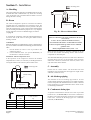
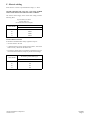
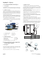
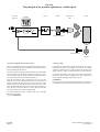
Instruction Manual
EN
CP COMPRESSOR
Model CPVS 40 - 50 - 60 - 75
62 305 258 65 ed00
CPVS 50
The CP Compressors should never be operated beyond its capabilities
or in any way which does not comply with the instructions contained
in this operating and maintenance guide.
Chicago Pneumatic Compressors will decline any responsibility
if these instructions are not respected.
This equipment has been factory tested and satisfies normal
operating conditions: they must not be exceeded
as this would place the machine under abnormal stress and effort.
INSTALLATION INSTRUCTIONS
For the guarantee to be valid, the unit must be assembled in covered
premises with temperatures not exceeding :
Mini: + 36 °F (frost free)
Maxi: + 104 °F
You must also have:
1 meter space around the compressor
low ventilation (fresh air) proportionate to the ventilation flow necessary for the machine and protected
from any infiltration of humidity (splashes of water during bad weather) and all pollution
top insulation or extraction to ensure reversal of the flow of warm air and evacuation of the heat to
outside the equipment room
a link from the condensation water evacuation pipe to the drain discharger
in dusty environment, pre-filtering the room's air intake and a special filter
on the machine's ventilation inlets
TECHNICAL DATA
VARIABLE SPEED MACHINES
CPVS Model
40
50
60
75
VERSION CPVS (as per ISO 1217 ed 1996)
Nominal pressure at full flow
PSI
Actual flow*
cfm
Motor power
hp
Ø Pressure outlet (F)
58
102
138
58
102
138
195.1 194.5 166.4 239.1 234.1 204.4
58
102
138
58
102
291.2 280.2 244.7 374.3
138
342.3 304.8
40
50
60
75
NPT
1.5"
1.5"
1.5"
1.5"
Capacity
gal
5,8
5,8
5,8
5,8
Carryover
ppm
3
3
3
3
Noise level at 3,3ft
dB(A)
65
66
67
70
(according to ISO 2157 + 3db(A))
* Suction pressure : 14.5 PSI absolute - Relative humidity : 0 % - Ambient temperature : 68 °F
- Effective delivery pressure : 102 PSI, 109 PSI, 138 PSI or 181 PSI (effective)
Dimensions (in)
L x Wx H
Approximate weight
lbs
01/2008
Page 2
75x37,4x69,3
75x37,4x69,3
75x37,4x69,3
75x37,4x69,3
1874
1995
2226
2679
Chicago Pneumatic Compressors
62 305 258 65
CPVS Model
Motor power
(hp)
40
50
60
75
40
50
60
75
Main Voltage 460 Volt / 3 / 60 Hz
Nominal current
(A)
Power supply cable
Fuse protection
(Type RK5)
69
81
89
125
AWG 4
AWG 3
AWG 1
AWG 0
80
100
125
150
Connection of the electric plate to an external control box
• Install an RC filter on the KM1 coil.
• Install an RC filter on the KM2 coil.
• All connections between external parts and the compressor must be carried out using a shielded cable, which must be grounded at one of its
ends.
WARNING: the operation connection cables between the different elements must never follow the same path as the existing power
cords. A separate installation from the power cords must be carried out.
• Install an RC filter on all the relay coils of the external operation units.
Chicago Pneumatic Compressors
62 305 258 65
01/2008
Page 3
CONTENTS
Space requirement and installation diagram : CPVS Model 40-50-60-75 ......................................................................................... 5
Section 1 - Description .................................................................................................................................................................................. 6
A - General Information ...................................................................................................................................................................... 6
B - Respect of the environment and prevention of pollution ............................................................................................................. 6
C - Standard equipment ...................................................................................................................................................................... 6
D - Definition of the pictograms ........................................................................................................................................................ 7
E - Electronic board ............................................................................................................................................................................ 7
Section 2 - Installation ................................................................................................................................................................................... 8
A - Handling ....................................................................................................................................................................................... 8
B - Room ............................................................................................................................................................................................ 8
C - Assembly ....................................................................................................................................................................................... 8
D - Air discharge piping ..................................................................................................................................................................... 8
E - Condensate drain pipes ................................................................................................................................................................. 8
F - Electric cabling ............................................................................................................................................................................. 9
Section 3 - Implementation ......................................................................................................................................................................... 10
A - Preparation for start-up ............................................................................................................................................................... 10
B - First start-up ............................................................................................................................................................................... 10
C -Discharge pressure adjustment .................................................................................................................................................... 10
D - Parallel compressor assembly ..................................................................................................................................................... 10
E - Safety .......................................................................................................................................................................................... 10
Section 4 - Operation ................................................................................................................................................................................... 11
A - Air and oil circuits ...................................................................................................................................................................... 11
Section 5 - Options ....................................................................................................................................................................................... 12
A - Level detection bleed valve ........................................................................................................................................................ 12
B - Advanced filtration to the compression air inlet ......................................................................................................................... 12
C - Pre-filtration panels .................................................................................................................................................................... 13
D - Automatic restarting ................................................................................................................................................................... 14
E - Remote starting and stopping ..................................................................................................................................................... 14
F - Rotation direction indicator - Phase controller ........................................................................................................................... 14
G - Centrifugal separator .................................................................................................................................................................. 15
Section 6 - Specific information for CPVS 40-50-60-75 ........................................................................................................................... 16
A - Description ................................................................................................................................................................................. 16
B - Safety .......................................................................................................................................................................................... 16
C - Installation .................................................................................................................................................................................. 16
D - Commissioning ........................................................................................................................................................................... 17
E - Operating incidents ..................................................................................................................................................................... 19
Section 7 - Maintenance .............................................................................................................................................................................. 20
A - Oil level and change ................................................................................................................................................................... 21
B - Air filter ...................................................................................................................................................................................... 21
C - Turbine ........................................................................................................................................................................................ 21
D - Oil and air cooler ........................................................................................................................................................................ 22
E - Oil separator ................................................................................................................................................................................ 22
F - Oil return pipe ............................................................................................................................................................................. 22
G - Draining condensation water ...................................................................................................................................................... 22
H - Temperature safety tests ............................................................................................................................................................. 22
I - Refastening electric connections .................................................................................................................................................. 22
J - Decommissioning the compressor at the end of its useful life .................................................................................................... 22
Section 8 - Operating incidents .................................................................................................................................................................. 23
A - Main incidents ............................................................................................................................................................................ 23
01/2008
Page 4
Chicago Pneumatic Compressors
62 305 258 65
Space requirement and installation diagram : CPVS Model 40-50-60-75
(see page 2 - installation instructions)
Fig. 1
75
Air outlet
Air outlet
Air inlet
3.9
44
69,3
1"1/2 NPT
AIR DELIVERY
3.9
2
Air inlet
7.6
16
5.9
1/4" NPT
Drain
7.6
37.4
25.8
66.5
66.5
A
* : POWER SUPPLY
* dia. 2.2
27
4.8
36
24.9
Air outlet
23
29.3
CPVS 40
CPVS 50
CPVS 60-75
14.7
19.6
27
15.3
A
13.4
Type
13.4
Dimensions (in)
Air inlet without deflector
Chicago Pneumatic Compressors
62 305 258 65
16
2.7
16
R 10.6
18.7
01/2008
Page 5
Section 1 - Description
A - General Information
The Chicago Pneumatic Compressors CP model air compressor
is a compressed air unit and is presented as an entire unit
completely assembled and tested. It is driven by an electric motor
and enclosed in a sound proof cowling which is necessary for
proper cooling.
The compression element is a single-stage, oil-refrigerated, rotary screw compressor. The oil is stored in a vertical tank, which
is fitted with an oil separator.
The compression element and the motor are fixed to the frame
using silent blocks.
B - Respect of the environment and
prevention of pollution
1 - Maintenance of the machine
Make sure that the used components of the machine (waste oil,
oil and air filters, oil separators, etc...) are disposed of according
to national and local regulations.
2 - Condensate bleed pipe
Make sure that the condensates (water, oil) are drained and treated
according to national and local regulations.
3 - End of life of the machine
Make sure that the machine as a whole is disposed of according to
national and local regulations ( See F Section 7 and J Section 8 ).
C - Standard equipment
In its standard version, the covered unit includes:
- Operating components:
1. A twinned screw-type compressor.
2. An electric motor: 3600 rpm, short-circuit rotor, 230/460V
or 575V voltage according to the model.
- Safety devices:
1. A safety valve mounted on the oil reservoir.
2. An thermal protection device for the motor, situated in the
starting box, to protect the motor from excessive overload.
3. An air temperature sensor that stops the compressor when
the temperature rises abnormally or during an oil cooling
defect.
- Control devices:
1. A minimum pressure valve located at the oil tank outlet,
just beyond the oil separator, which guarantees minimum
pressure in the lubrication circuit.
2. Automatic draining allowing the unit to be exposed to the
atmosphere when stopping to thus ensure empty start up
which relieves the motor,
3. An oil level gauge on the front panel ( see fig. 19).
4. An electronic controller including:
– a control keyboard,
– the main safety and control indications.
5. The pressure sensor ensures control over the compressed
air flow.
The CP compressed air unit has been designed, produced and
tested in accordance with the following recommendations, codes
and standards :
- machine safety : European Directive 98/37/CE, 91/368/CEE and
93/68/CEE.
- pressure vessels: European Directive for simple pressure vessels
n° 87/404/CEE.
- electrical equipment :
• electrical equipment : European Directive Low tension
73/23/CEE.
• electromagnetic compatibility European Directive: 89/336/CEE,
92/31/CEE.
- performance levels: ISO 1217 : 1996.
- noise level : ISO 2157 + 3db(A)
- European Directive 97/23/EC
" Pressure Equipment Directive ".
3. Star delta starting.
4. A direct drive or gearbox drive .
5. Air and oil tank in compliance with applicable legislation
ASME
6. "All or nothing" regulation for the aspiration vent.
7. A greasing system using the circuit's differential pressure,
thus avoiding the need for an oil pump.
8. An oil separator based oil separation system.
9. A heat discharge system : oil and compressed air radiator
with forced ventilation.
10. A dry air filter.
11. An oil filter.
12. A command and control electronic board.
01/2008
Page 6
Chicago Pneumatic Compressors
62 305 258 65
D - Definition of the pictograms
Typical examples of pictograms valid for CP Compressors:
1.
2.
3.
4.
5.
Water outlet
Manual condensation water draining
Water inlet
Automatic condensation water draining
Unplug and decompress the compressor
before maintenance
6. Hot parts
DANGER
This symbol identifies immediate hazards which will
result in severe personal injury, death or substantial
property damage.
CAUTION
Identifies hazards or unsafe practies which could
result in minor personal injury or property damage.
DANGER
This symbol identifies life threatening electrical
voltage levels which will result in severe personal
injury or death. All electrical work must be
performed by a qualified electrician.
CAUTION
This symbol identifies hot surfaces which coold
result in personal injury or property damage.
E - Electronic board
See the specific instructions for a description of the electronic
plate, together with operating instructions :
Notice N° 62 305 169 xx for version CPVS
Chicago Pneumatic Compressors
62 305 258 65
01/2008
Page 7
Section 2 - Installation
Prevailing wind
A - Handling
The CPVS Compressor must always be handled with care. It may
be lifted either with a forklift truck or by means of a travelling
crane. In the latter case, precautions must be taken so as not to
damage the unit's cowling.
L
Flexible fitting
V
B - Room
The CPVS is designed to operate in a frost-free environment,
supplied with air at a temperature of no more than 104 °F. The
premises must be well-aired and as close as possible to the place
where the compressed air is used. A space must be left around the
unit, for cleaning and maintenance purposes. It is very important
for the compressor to have an abundant supply of fresh air.
(see page 2).
If operating the compressor causes the ambient temperature to
rise above 104 °F, the warm air leaving the radiator must be
discharge outside.
Compressor
Fig. 2b - Sleeve with an elbow
V maxi = 18.04 ft/s
(Ratio of volume flow rate of the ventilation to the sleeve
cross section)
L maxi = 32.8 ft (without mechanical extractor)
COMMENT
When the atmosphere is contaminated by organic or mineral dust or
by corrosive chemical emanations the following precautions must be
taken:
1. Provide another air inlet as close as possible to the
compressor suction.
2. Use an additional filter. (see options Section 5), on
the machine's ventilation intakes.
Installation with heat dispersion sleeve
If the operation of the compressor increases the ambient
temperature above 104 °F, it is necessary to discharge the hot air
leaving the radiator to the exterior by means of the sleeve.
Prevailing wind
Cross section of room air inlet > 2 x Duct outlet cross section
2 elbows accepted with large radius of curve and fluid
guidance vanes
Ratio (Length/Width of sleeve) maxi = 1.6
Make sure that no outside air, especially if humid, can be fed
back into the machine and damage electric and electronic
components or rust metal parts.
The maximum admissible pressure loss of the sleeve should not
exceed 30 Pa (0.12 in CE). In case of higher value, provide an
additional ventilation (mechanical extractor) with a flow
equivalent to that of the machine.
C - Assembly
Put the unit on a stable surface. The CPVS does not need
foundations. Any flat surface that can support its weight will be
sufficient (industrial floor).
V
L
Flexible fitting
D - Air discharge piping
The diameter of the air discharge pipe must be at least
2"NPT.Current legislation requires that a valve which is lockable
in the closed position be installed at the air box outlet, connected
to the compressor by a union and flexible line to allow it to be
cut off during maintenance.
Compressor
Fig. 2a - Sleeve with roof outlet
E - Condensate drain pipes
d
Duct minimum cross section
( d ≤ L ≤ 1,6d )
sqf
CPVS 40
2860
2.6
CPVS 50
2860
2.6
CPVS 60
3920
3.6
CPVS 75
5300
4.9
L
Ventilation
flow rate
cfm
01/2008
Page 8
A separator with automatic solenoid valve drain is provided
inside the set ( see Section 5-K) to remove the condensate at
the final cooler outlet and stop the compressor pipe condensate
return lines. Connect the discharge pipe to a condensate
manifold.(see B Section 1)
Chicago Pneumatic Compressors
62 305 258 65
F - Electric cabling
Each CPVS is wired for a pre-determined voltage, i.e. 460 V.
NEVER OPERATE THE CPVS ON A VOLTAGE OTHER
THAN THAT SHOWN ON THE ELECTRIC CABINET.
The electric current supply to the CPVS must comply with the
following table :
Type of cable to be used :
Power cable size
(for a maximum 32.8 ft length)
VOLTAGE
CPVS Model
460 V
40
AWG4
50
AWG3
60
AGW1
75
AWG0
SAFETY REGULATIONS
It should be remembered that safety regulations require :
• An earth socket to be used.
• A manual isolating switch, cutting all three phases ; this switch
must be clearly visible near the CPVS unit.
• The electric current must be cut whenever maintenance work is
carried out on the machine (except for pressurized oil change)
CPVS Model
Fuses to be used for
the isolating switch (RK5 type)
460 V
40
80
50
100
60
125
75
150
Chicago Pneumatic Compressors
62 305 258 65
01/2008
Page 9
Section 3 - Implementation
A - Preparation for start-up
Before starting the set for the first time, the operator must get to
know the different systems. The main locations which have to be
examined are shown on the figures.
IMPORTANT
Before start up, make sure that transport red wedges have been
effectively removed.
ATTENTION
The power circuit must be turned whenever adjusting electrical
equipment or to prevent accidental starting.
Loosening of electrical power cables that may be due to vibrations
caused by transport or initial heating entails abnormal heating of
contactors, which may even destroy them. Therefore, these cables
must be re-tightened at line contactor incoming and outgoing, star
and triangle before use.
Before start-up, check the following points :
1 - Make sure that the unit is properly grounded.
2 - Check the oil level in the tank.
NOTE : the tank has been filled with suitable oil in the
factory. See Section 8 - A for the quality of oil to be used
or for oil renewal conditions.
3 - Make sure the oil change valve is properly closed.
ATTENTION
The oil filler cap, the oil change valve and plugs must always
remain closed during operation and never be opened before the
system has been completely vented to atmospheric pressure
(except pressurized oil change : See Chapitre 8 - A).
B - First start-up
Check the voltage between the three phases before using the unit
for the first time.
Check the direction of rotation (following the arrow on the coupling
housing rep. 1- Fig. 3) by pressing the "Start" button, followed
immediately by the emergency stop. If it does not spin in the right
direction reverse two stages of the power cord. When it rotates in
the correct direction, the oil level (Fig. 19) should drop after 4 or
5 seconds of operation.
It is also very important to verify the direction of rotation of the
fan (indicated on it by an arrow) anti-clockwise seen from inside
the machine or clockwise seen from outside the machine).
1 - Press the ON button, the motor starts up.
2 - Leave it running for a few minutes with the discharge valve
slightly open to observe the compressor under load. Ensure
that there are no leaks. Reblock the connectors if necessary.
3 - Press the OFF button. The motor will stop and the unit
will automatically vent to atmospheric pressure.
C -Discharge pressure adjustment
The unit is adjusted in the factory for a MAXIMUM pressure
(for the maximum output from the outlet of the central unit) of
100, 125, 150 or 175 PSI . To adjust the backflow pressure setting
to a lower value, refer to the manual of the electronic plate (refer
E Section 1).
D - Parallel compressor assembly
If the CPVS is intended to operate in parallel with other CP or
similar compressors, the discharge piping can be linked together.
If the CPVS is intended to operate in parallel with other CP or
similar compressors, there must be an air tank common to all the
alternative compressors. The pulses emitted by alternative
compressors may cause serious damage to the minimum pressure
valve and the CPVS oil separator, and disrupt the regulation system.
When the rotary compressor is operating in parallel with an alternative compressor, the latter should be adjusted so that the rotary
compressor takes the main load. It is cheaper to run this way.
E - Safety
The oil used for cooling the machine is a liquid combustible under
the effect of strong heat. In case of fire in the machine, it is essential
to respect the regulatory measures on the compressor. The type of
fire in a compressor is defined as "class B" and in presence of a live
electrical conductor, it is recommended to use a CO2 extinguisher
functioning by "smothering" (starvation of oxygen) while observing
the user instructions applicable to the model.
1
Fig. 3
01/2008
Page 10
Chicago Pneumatic Compressors
62 305 258 65
Section 4 - Operation
Key fig. 4
A - Air and oil circuits
20
Compressor
21
Suction element
The air is sucked into the compressor through a filter (rep. 23).
This air passes through the compression element where it is mixed
with oil injected during compression. Inside the oil tank, the
compressed air is pre-deoiled by shocks, then flows through the
oil separator (rep 49). It then passes through the mini pressure
valve (rep 34) forming a check valve, the aftercooler (rep 51A),
the condensate separator (in option), and lastly the outlet valve
(not supplied) to which the distribution pipe is connected.
23
Air filter
26
Oil filter
34
Minimum pressure valve
41
Ventilator
47
Thermostat valve
49
Oil separator
2 - Oil circuit (see Fig. 4)
51 A
Air cooler
The oil, under discharge pressure, flows from the bottom of the tank
through the cooler (rep. 51H), the oil filter (rep. 26) which retains solid
impurities, and then into the compressor (rep. 20). At each cold start,
the thermostat valve (rep. 47) short circuits the oil radiator, thus enabling
the optimum operating temperature to be attained quickly. When it
leaves the compressor, the oil returns to the tank. Part of the oil remains
suspended in the air as mist. This mist passes through the oil separator.
(rep. 49). The remaining oil, which is separated by the last stage of the
oil separator, is drawn up by a dip tube and dispatched to the
compressor.
51 H
Oil cooler
56
Main motor
57
Tank
1 - Air circuits (see Fig. 4)
Fig. 4 - Air / oil circuit
34
26
47
49
57
21
23
56
51A
51H
20
41
Chicago Pneumatic Compressors
62 305 258 65
01/2008
Page 11
Section 5 - Options
A - Level detection bleed valve (Fig. 6)
2 - Option overview
- This option is used as a replacement for the standard filter
1 - Description
The BEKOMAT type level detection bleed valve allows all air
consumption to be avoided while the compressor is not running.
2 - Option overview
- There is no air consumption due to the level detection system : an
inductive sensor detects the level of condensation and thus controls
the opening of the electric bleed valve. A low level of condensation is
also detected in order to close the electric bleed valve and to prevent
compressed air from being wasted.
- This type of purge valve does not require any maintenance. The
purge valve does not require the use of the metallic intake filter that is
usually installed on electronic purge valves to protect the solenoid
valve. The solenoid valve will not be damaged.
- Condensate treatment is made easier because it is not evacuated by
pressure, which enables easy separation of the water and oil stages.
Fig. 6
1 1
- Certain atmospheric particles are smaller than 7810-6 in, a limiting
threshold for traditional paper cartridge filters. The filter increases
filtration effectiveness by eliminating 99.97% of particles that
are larger than or equal to 11810-6 in.
- The quality of the air intake by a compressor is essential. Low
quality air creates the following :
• Quick pollution of the oil thus an increase in draining cycles.
• Binding of the air / oil separator before 4000 hours thus an
increase in maintenance cycles and operation costs.
• Pollution increases the elements that filter into the air and oil,
speeding up the damage to the mechanical components of the
compressor, screw element,...
Filters in compliance with standard ISO 5011/2000.
- Exceptional filter longevity, from 18 months to 3 years of
continuous service (24 hours a day, 7 days a week), which is a
little more than 10,000 hours of operation of the compressor under
normal conditions.
- Installation of the filter(s), depending on the model, outside the
compressor, for intake of fresh air, hence resulting in a lower oil
temperature and more efficient compression (Fig. 7a and 7b).
Extraction duct
44
VORTEX pre-filter
2 2
55
Air filter
66
3 3
1 - Condensation intake
4 - Main duct
2 - Capacitive sensor
5 - Electric valve
3 - Receiver
6 - Membrane
3 - Technical features
Maximum capacity of the compressor : 706 cfm/min
Working pressure
: 11.6 / 232 PSI
Operating pressure
: 33.8 / + 140°F
Electric power supply
: 115V / 24V
AC socket in the compressor electric cabinet.
B -Advanced filtration to the compression
air inlet (Fig. 7a and 7b)
x
y
x
y
CPVS 40-50-60
71 in
11.2 in
CPVS 75
71 in
13.6 in
Fig. 7a
Cartridge
1 - Description
This system is equipped for "high efficiency" air filtration in order
to improve the quality of the air intake and to preserve the
compressor's oil and internal filter components.
This option is particularly useful in very dusty surroundings.
Fig. 7b
01/2008
Page 12
Chicago Pneumatic Compressors
62 305 258 65
3 - Technical features
Operating temperature :
-104 °F to + 194 °F
C - Pre-filtration panels
Fig. 8
• Binding of the air / oil separator before 6000 Hours thus an
increase in maintenance cycles and maintenance costs.
Access to the filtering medium is allowed by removal that does
not require any particular tool. The panel frame can be unlocked
manually in order to clean the medium.
Exceptional longevity of the medium that is quick to take apart.
The medium can be scoured by blowing compressed air in thus
increasing the usage term for the filtering medium.
Galvanised steel covered frame.
Flammable medium (belonging to fire protection class M1) made
of polyester fibres.
Pleated medium on support grid placed downwards in the direction
of the airflow.
Support grid
Easy to disassemble for rapid cleaning
Fig. 9
Pre-ventilation lock
2 pannels
1 - Description
Installing air filtration panels on the ventilation intakes (machine
and built-in dryer) guarantees protection of the compressor's
internal components and an increase in air sucked into the
compression assembly. This option is recommended if the forced
filtration option is installed (see § B).
2 - Option overview
15.75 in
Disassembly hinges
The pre-filtration panels eliminate 90% of the particles normally
admitted inside the compressor and considerably decrease internal
contamination of the machine.
The high quality of the ventilation air is also essential for protecting
internal components of the compressor and, more specifically,
the motor and the air / air and air / oil exchangers. Clogging in the
exchangers creates an increase in temperature, deterioration of the
lubricant and the motor becomes overloaded thus increasing the
energy consumed.
The quality of the air drawn in by a compressor is essential. Low
quality air results in the following :
• Fast pollution of the oil thus an increase in oil change cycles.
• Increased pollution of the air and oil filtering components that
increases the deterioration of the mechanical components in the
compressor, screw block, ...
Chicago Pneumatic Compressors
62 305 258 65
3 - Technical features
FILTER MEDIUM :
Degree of filtration : 90% of the dust emitted is filtered.
Total nominal flow :
324893 cfm/h
Filter panel number :
2
Initial charge loss :
75 Pa
Dimensions :
Width :
24 in
Length :
24 in
Thickness :
7.9 in
01/2008
Page 13
D -Automatic restarting
1 - Description
This management system enables the compressor to be restarted
automatically after a power outage.
2 - Option overview
Not available in standard version in order to prevent any incident
during maintenance operations carried out by an untrained person.
This option is proposed in cases where the production of
compressed air should suffer only the minimum periods of
shutdowns.
The standard microcut time accepted by AIRLOGIC is
approximately : 250 ms.
However, certain electrical fittings create longer micro cut-offs
that will cause a compressor shut down, then a manual restart.
Automatic compressor restarting enables immediate air production after a power outage and thus avoids the time lapse required
for manual compressor restarting that would mean a fall in pressure in the air circuit.
Particularly used for industries where air production should not
be subject to shut downs that waste the products manufactured
or damage the production equipment.
THIS OPERATION REQUIRES THE CONFIGURATION
OF MENUS IN THE CONTROLLER, ACCESS
RESTRICTED TO TECHNICIANS CERTIFIED BY
CHICAGO PNEUMATIC COMPRESSORS.
AN INFORMATIVE INSERT MUST BE PLACED
ON THE ELECTRIC CABINET TO WARN THE
USER OF THE RISK THAT THE COMPRESSOR
MAY AUTOMATICALLY RESTART AT ANY
TIME.
3 - Technical features
This option requires configuration of the electronic plate and
installation of an informative insert on the door of the compressor
electric cabinet.
F - Rotation direction indicator Phase controller
1 - Description
The phase controller option is designed to:
- control the rotation direction of the machine's electric power
supply phases.
- check that electric power is supplied to each phase.
These two functions are permanently guaranteed.
2 - Option overview
The advantages of this option are:
- starting the machine with the guarantee that it will work (if this
option was factory-installed), the configuration of the rotation
direction having been configured during the production tests.
- protecting the motor and the electrical fittings from any loss of
power supply (phase cuts, blown fuses, voltage threshold lower
than 130 volts).
- protecting the machine (motor and especially the compression
assembly) when restarting it following electrical work on the power
supply line or when switching from the mains supply to a backup
power supply, such as a power generator.
3 - Operation
In the event of a phase failure (detectable by this option) or an
incorrect rotation direction, the trip switch sets off the machine's
safety system (preventing immediate stopping and starting of the
machine) and shows the following message on the display of the
electronic plate: "ventilation flaw".
4 - Features
scanning time / measurement cycle
minimum operating voltage
maximum acceptable voltage between phases
power consumption
< 80 ms
200 volts
600 volts
15 VA
Every time the compressor stops, it must be secured by
opening and locking the electric section switch.
E - Remote starting and stopping
This option allows the compressor to be remotely started and
stopped. However, in all cases, stopping the compressor at
the machine itself is essential. If the compressor is shut down
from a distance, it may be restarted from a distance as well. For
any intervention to be conducted on the machine, it is essential to
activate the emergency stop of the machine in order to ensure safe
conditions (Refer to AIRLOGIC Manual, E Section 1)
01/2008
Page 14
Chicago Pneumatic Compressors
62 305 258 65
G - Centrifugal separator (See B Section 3)
Fig. 13
1 - Description
This device allows bleeding of the condensates formed in the air
cooler.
2 - Description of the option
The cooling of the compressed air allows the suction air to be
dried, thus removing the humidity that collects in the bottom of
the separator after being condensed in the aftercooler. The
condensates are evacuated from the separator through a trap with
a solenoid drip valve or a trap with level detector if this option is
installed.
Chicago Pneumatic Compressors
62 305 258 65
01/2008
Page 15
Section 6 - Specific information for CPVS 40-50-60-75
Refer also to the chapters concerning the standard machine.
"CPVS" compressors are compliant with the Electromagnetic
compatibility in industrial environments Standards 50081-2 and
50082-2
A - Description (cf Section 1)
Standard equipment
A electronic frequency adjusting device replaces the star-delta
starter.
A fuse holder section switch completes CP standard's safety
devices.
4
2 - Safety instructions
No connection work is allowed when the inverter is
1 under power.
No measurement work is allowed on the inverter when
2 it is under power.
B - Safety
For your safety, please respect the instructions carrying the warning
symbols as given below:
The inverter has a load circuit of thermally limited
capacitors. Therefore, it is important to allow minimum
5 minutes between two successive power-ons. If this
instruction is not respected, the switch and the resistor
of the load circuit may be damaged.
3
To undertake any work on the inverter, it is necessary
to disconnect the equipment from the mains. Wait for
the internal ventilation to stop and the indicators to be
turned off. Then, wait 5 minutes before opening the
cover.
No voltage or insulation verification test is allowed on
SAFETY RULES
4 the inverter components.
The safety rules require:
• The presence of an earth socket
• The existence of a manual switch cutting-off the three pha-
ses that should be placed visibly near the CP
• It is necessary to cut out the electric current before any
intervention on the machine (except drainage under pressure).
= Dangerous voltage
Disconnect the cables from the motor and the inverter
5 before taking measurements on them.
Do not touch the integrated circuits, the electrostatic
6 discharges may damage them.
Before connecting the inverter, make sure that its cover
7 is properly closed.
Make sure that no compensation capacitor of cosine
= Attention
ELECTRICAL INSTALLATIONS MUST ONLY BE
CARRIED OUT BY A SPECIALISED AND COMPETENT
TECHNICIANS
1 - Warning
1
2
3
01/2008
Page 16
The internal components and the plates (except the
electrically insulated I/O terminals) are at the mains
voltage when the inverter is connected to the mains.
This voltage is extremely dangerous and can cause
severe injuries or even death in case of involuntary
contact.
When the inverter is connected to the mains, the
connection terminals U, V, W of the motor as well as
+/- connectors of the braking resistors are under power
even if the motor is not running.
The I/O control terminals are insulated from the mains,
the relay outputs can nevertheless be under power
even if the inverter is disconnected. This also applies
to other I/O control terminals even if the X4 switch is
in OFF position (Stop).
8 phi is connected to the motor cable.
C - Installation
The "CPVS" must be installed away from a transformer or
autotransformer.
(see Section 2 and 3).
The fuses for the section switch are defined as follows
Main Voltage 460 Volt / 3 / 60 Hz
Nominal current (A)
Power supply cable
Fuse protection (Type RK5)
40
69
50
81
60
100
75
126
AWG4 AWG3 AWG1 AWG0
80
100
125
150
ATTENTION
Motors and drives can only be guaranteed where the supply voltage does not exceed the rated voltage by more than 10%.
The connection of the power supply to the section switch (so
present) requires the use of properly insulated terminals.
Chicago Pneumatic Compressors
62 305 258 65
D - Commissioning
1 - Preparation for start-up
(See Section 3).
ATTENTION
The power circuit will have to be cut off when adjusting the
electrical equipment or if inadvertent start-up is to be avoided.
Before start-up, check the following points:
1 - Ensure that the unit has a suitable earth,
2 - Check the oil level in the compressor,
NOTE: the tank was filled in the factory with a suitable oil. See
Section 8 - A for the quality of oil to be used and for the oil
renewal conditions.
3 - Check that the drainage valve is properly closed.
4 - Make sure that the conveyor assembly's blocking lugs
(compressor) have been removed from the compressor
silentblocks.
4 - Assembly and settings for parallel operation
with other compressors
Pressure for the CPVS compressor must be adjusted at a value
within the range of adjustment values for the rest of the
compressors..
Adjustments pressure
Stop P
Set
point 1
Various
compressors
ATTENTION
The oil filler plug, the valve and the drainage plugs have always to
be closed during operation and must never be opened before the
system has reached atmospheric pressure.
CPVS
C1
C2
C3
2 - Control of rotation direction on start up
5 - Regulating the pressure by changing the speed
This control must be implemented when the machine is put into
operation for the first time, after any work has been carried out on
the motor and after any changes to the mains supply.
This method of regulating the pressure allows precise adjustment
of the compressor's flow-rate at the compressed air demand valve:
IMPORTANT :
The accuracy is of the order of 1.45 PSI when pressure regulation
is achieved by changing the speed, provided that the flow-rate
lies between the maximum and minimum rates for the machine.
• Check the direction of rotation (as per the arrow shown on the
sump) by jogging over with the START button.
• The principle of the pressure regulation by changing the
speed
If it is incorrect, swap over two of the motor's phase cables under
the drive.
The AIRLOGIC controller controls the motor and the compressor
as a function of the system pressure as measured by an internal
pressure sensor (fig. 14a).
When rotating in the right direction, the oil level (fig. 19) must
drop after 4 to 5 seconds of operation.
• Also check the direction of rotation of the fan for air-cooled
plants (counter-clockwise, as seen from inside the casing).
1 - Press the START button so that the motor starts.
2 - Allow to rotate for several seconds with the discharge valve
slightly open to observe the compressor at load.
3 - Press the STOP button. The motor stops and the plant
automatically returns to atmospheric pressure.
3 - Setting of pressure - machine
(Refer E Section 1 refer also to the AIRLOGIC controller manual)
The unit is factory pre-set for a given delivery pressure. As an
energy saving measure, it is strongly advised to reduce the pressure to the exact requirement by adjusting the "Set point 1"setting.
The stop pressure"Indirect shutdown"used when running at less
than the minimum flow-rate - must be set to 7.25 PSI above that
of the "Set point 1". In this way, the current used by the compressor
is minimised (seenotice AIRLOGIC).
- If the mains pressure is weaker than the pressure set point
(user-defined parameter in the AIRLOGIC) the motor will
accelerate and the pressure will increase (fig. 14b)
- If the mains pressure is stronger than the pressure set point, the
motor will slow down causing the pressure to drop.
The AIRLOGIC provides the compressor control functions and
also controls the whole pressure feedback loop. It therefore includes
a device to compare the indicated pressure with that from the
pressure sensor, associated with a compensating device,
Proportional integral control PI (fig. 14c).
The drive, a result of the latest developments in power electronics,
is one of the smallest in size on the market, thanks to its use of
high cut-out frequencies with IGBT transistors.
At the same time, the motor control method known as "open loop
vector flux control " provides good stability for the system against
disruption.
In this way, the pressure feedback loop is more stable to sudden
changes in consumption (changes in the flow-rate).
Do not set the stop pressure at a level beyond the machine's max P.
Chicago Pneumatic Compressors
62 305 258 65
01/2008
Page 17
Fig. 14a
The principle of the pressure regulation by variable speed
Pressure
required
Controller
Drive
Motor
Compressor
unit
Tank
Frequency speed
Pressure sensor
System
• Pressure regulation for low rates of flow
• Energy saving
For an air consumption rate lower than the minimum rate of flow
for the machine, the pressure is adjusted by the machine's timedelayed START/STOP controls.
For demand of compressed air within the machine's flow range min flow to max flow, the frequency converter or the variable
speed drive feed the motor in order to ensure that it turns at the
speed required to supply air demand both for pressure and flow.
Since the operation element cannot function below a certain speed
(corresponding to the minimum output), the compressor continues to run and compress at the minimum speed until the pressure reaches the limit called "Indirect shutdown ".
Once this threshold has been reached, the motor will stop, the
machine will go into stand-by mode after a certain period of
inactivity and the full drainage process will be carried out.The
pressure then drops towards the indicated pressure and, at the
end of the minimum time delay (since reaching the no-load pressure), the drive allows the motor to restart. The pressure then
rises again and the cycle starts over (fig. 14 d).
It is used to adjust the power supply to the motor (and thus the
machine) to the exact power requirement for the compression of
the air, without a drainage stage being necessary.
COMMENT :
Energy savings are increased if machine maintenance is carried out
in accordance with the maintenance instructions and frequency.
To avoid pumping the system - frequent stop / start - drainage
time may be increased
(cf. notice AIRLOGIC).
01/2008
Page 18
Chicago Pneumatic Compressors
62 305 258 65
Fig. 14b
5b
Fig.
Fig. 514c
c
Fig.
Fig. 14d
5d
Fig.
Pressure
Stop
threshold
Instructions
Required
pressure
Time
Speed
stop timing
minimun time
Min speed
Time
Flow Q
Min Q
Time
E - Operating incidents
The staff in charge of maintenance of the CPVS compressor must become fully acquainted with this machine, in order to be able to easily
diagnose any anomaly. Under normal operating conditions, the CPVS compressor must provide full satisfaction.
1 - Main incidents
The main incidents likely to occur are listed below, along with the remedies to be applied. The keys to the control lamps relate to the instrument
panel (refer to the AIRLOGIC Manual - E Section 1).
Chicago Pneumatic Compressors
62 305 258 65
01/2008
Page 19
Section 7 - Maintenance
The summary on the CP instrument panel shows at a glance the
type and periodicity of operations to be carried out for the
compressor to function correctly.
The maintenance period is limited to several essential operations. It
is strongly recommended that the power supply be cut off during
any adjustment or repair.
Operations to be carried out
Parts
Daily
Draining cock
X
Oil level
X
Every
500 hr
Every
Every
Every
Every
150 hr 2 000 hr (*) 4 000 hr 6 000 hr
Service A
Service B
Air filter
Oil tank,
Oil change
X
X
Oil return pipe
Oil separator
X
X
X
X
Control
cleaning
lubrication
Valve at minimum
pressure
Electric cabinet
Safety temperature
test
X
X
Observations
Oil change, oil refill
with recommended oil
(Section 8 - A)
Renovation of the
Overhaul kit housing. Use the
suction housing kit
Check the cleanliness of
Overhaul the oil return pipe and
Kits
the state of the seal
(Section 8 - F)
Change the part
according to the
instrument panel indication
(Section 8 - E)
Filter change
Blowing of cooling
elements
Cleaning (Section 8 - D)
Exchange the accessories
Overhaul
supplied with the
kits
maintenance kit
For motors fitted with
grease, use
Type ESSO
UNIREX N3 (0.53 ocs
per grease fitting)
X
Control
cleaning
lubrication
Motor for
CPVS
40-50-60-75
Every
12 000 hr
Service C
Drain the condensates
from the cold oil circuit
(Section 8 - G)
Check and top up if
necessary
(Section 8 - A)
Replace the filter
Suction housing
Oil filter
Oil radiator
Final coolant
Every
8 000 hr
X
Retighten power cable
connections.
Check operation
(Section 8 - H)
X
NOTE : maintenance kits are available (see spare parts list).
(*) or at least every year
CAUTION
When the compressed air cools, part of the moisture sucked in by the compressor condenses. In order to protect the dryer against
the risk of an ice plug forming, it is essential to check regularly that the condensate drains are operating properly :
On the compressed air storage reservoir and on the filters :
• With a manual drain, drain regularly according to the moisture content of the ambient air.
• With an automatic drain, set the draining cycle accordingly and check that the drain is in good working condition.
This recommendation is also fundamental in a circuit comprising an absorption dryer (risk of saturation of the alumina).
01/2008
Page 20
Chicago Pneumatic Compressors
62 305 258 65
A - Oil level and change (see fig. 19)
(see B Section 1)
The recommended oil used for the first compressor fill up is a
mineral oil with the following properties :
-
viscosity: 40 cSt at 104 °F
viscosity index: 90 minimum
antioxidant additives
anti-rust additives
anti-foam additives
THE FIRST OIL CHANGE MUST BE CARRIED OUT
AFTER THE FIRST 500 HOURS OPERATION.
Using a synthetic oil for compressors is also acceptable and means
less frequent oil changes: please speak to us about the compatibility
and oil change methodes.
The oil change and the replacement of oil filter must be carried out
when the indication is seen on the electronic controller and when
the corresponding time counter reaches "0" (refer to electronic
plate manual Section 1 E ).
Drain the compressor when warm. For this, shut it down taking
care to disconnect the power cable. Release pressure in the tank
by unscrewing the filler plug by a single turn. Open the purge
valve and drain the oil. Do not forget to close the valve after
draining the oil.
After maintenance, reset the time counter which tells you how
long you have before the next oil change is due, refer to electronic
plate manual Section 1 E.
NOTE
If the oil is in a bad state ; that is a pungent smell or contains
particles or varnish or other solid matter, the system will have to
be rinsed : pour about 50% or the normal contents of clean oil
and operate the unit for 3 hours and carefully change the oil.
During rinsing, leave the old oil filter cartridge in the machine.
B - Air filter
(see B Section 1)
The air filter is of the dry, encapsulated type. Change the
cartridge every 2,000 hours. Check the cleanliness of the filter
every week and change it if necessary. (see notice on the
electronic plate for resetting the time).
ATTENTION :
If you do not replace the filtering element when needed, permanent dirt build-up will result. This reduces the air inflow to the
compressor and could damage the oil separator and the compressor.
Fig. 19 - Oil level
Filler plug
OIL LEVEL
When the machine is not running, the MAXIMUM oil level corresponds to the top part of the green area, and the MINIMUM
level is represented by the low part of this green area.
Oil level
CHECKING THE OIL LEVEL MUST BE CARRIED OUT
JUST AFTER STOPPING THE MACHINE (THERMOSTAT
VALVE OPEN).
DRAINAGE UNDER PRESSURE
So as to carry out a quick and full oil change, your CPVS is equipped with a system that allows low level pressure to be maintained
in the oil circuit. This pressure is shown by the pressure gauge
situated in the tank. (see Notice AIRLOGIC - E Section 1).
Proceed as follows :
• When hot, compressor in load for programming a shutdown under
pressure (refer notice AIRLOGIC § 4.9.3). The machine is
emptied and stops automatically.
• Change the oil by opening the oil change valve very slowly.
• When there is no pressure left in the oil tank, change the oil filter
cartridge.
• As soon as the oil is no longer flowing, close the valve and refill
with new oil.
• Reinitialise the timers that will warn you when to carry out the
next oil change and the next oil filter change
(see the AIRLOGIC Manual - E Section 1),
• Reseal the filler cap when replacing it and check that all openings
are properly closed.
• The machine can be restarted only after pressing the button C
several times to return to STATE 0.1. Check the clamping of
connections.
• After restarting, check that there are no oil leaks.
Chicago Pneumatic Compressors
62 305 258 65
Drainage
C - Turbine
Replacement of the complete fan is recommended if one or more
blades are deformed or broken If replaced, check the fan rotation
direction reversal of the rotation direction will reduce machine
cooling and damage the motor in time.
01/2008
Page 21
D - Oil and air cooler
Fig. 20 - Oil return pipe
The aluminium oil and air cooler is a vital part in the CPVS system.
Please take care of this element. To prevent the nest of tubes from
being deformed or damaged, when assembling or disassembling
the radiator unions and hoses, the radiator sleeves' must be kept
rotating by means of a wrench. The outer surface of the nest of
tubes must always be kept clean in order to enable proper heat
transfer. In the event of a leak, the source of the leak must be
detected. In order to do this:
64
- Stop the CPVS.
- Clean the greasy areas.
- Look for leaks using conventional means (soap solution, …).
Pressurized shutdown retains the pressure in the machine circuit
for a few moments so that any leak can be more easily located.
E - Oil separator (see B Section 1)
G - Draining condensation water
(see B Section 1)
The oil separator's lifespan depends on the cleanliness of the air
coming into the compressor, on regular oil filter changes, on the quality of the oil used, on the attention with which the oil tank condensate
drains are carried out and on the ambient temperature of the room.
(see notice on the electronic plate for resetting the time).
Condensation water prevents proper lubrication. The resulting
substantial wear leads to a reduction in the lifespan of the CPVS. It is
therefore essential to drain condensation water.
Check the cleanliness of the pipe that returns the oil to be aspired
(transparent) to prevent the injector from becoming blocked and
to ensure that the oil recovered can pass through easily.
Draining will only take place at least 12 hours after the CPVS has
been shut down. It can be carried out for example on the morning
of the start-up.
Excessive oil consumption
To do this :
The presence of excess oil in the discharge air, a rapid drop in
level show a probable deterioration in the oil separator that must
be changed.
- Slowly open the oil change tap and let the water escape.
- When the oil appears, close the valve immediately to avoid any
loss.
- Refill with oil if necessary.
The unit must first be checked to make sure that there is no oil
loss and that the oil return is working properly.
H - Temperature safety tests
Changing the oil separator
Dismantle all the piping connected to the tank's upper flange (air
discharge, regulation system supply, and oil return). Undo the
screws that hold the tank cover and remove it.
- If the old oil separator musty be remounted, use new seals.
- Be very careful during installation of the oil separator so as to
avoid possible damage.
- The new oil separator is delivered with its two seals on either
side of the flange.
- Slight undulations in the flange will flatten out when the screws
are tightened.
- Apply a 6 mkg torque.
- Replace the oil return tube correctly so it touches the bottom of
the oil separator.
F - Oil return pipe (see fig. 20)
Placed under the compressor
•
•
•
•
Dismantle the body of the anti-oil return pipe.
Lift the anti-oil return pipe.
Check the state of the o-ring (rep. 64).
Reassemble.
01/2008
Page 22
Draining of condensates in the oil circuit (see fig. 19) :
(See instructions electronic board).
IF THE SENSOR IS NOT WORKING, IT MUST BE
CHANGED.
I - Refastening electric connections
A loosening of the electric power cables leads to the contactors
ove-rheating which can lead to their destruction.
Periodic refastening is therefore necessary at the star and triangle
line contactor arrivals and departures. (see Maintenance Table).
All electric power supply to the machine must be cut off before
opening the electric cabinet.
J - Decommissioning the compressor at
the end of its useful life (see B Section 1)
1. Stop the compressor and close the air outlet valve.
2. Unplug the compressor from the electric supply.
3. Decompress the compressor : unplug the 4/6 piping on the
oil separator cover.
4. Close and decompress the section of the air network which
is linked to the exit valve. Disconnect from the compressed
air exit pipe from the air network.
5. Empty the circuits of oil and condensates.
6. Disconnect the compressor condensate piping from the
condensate draining system.
Chicago Pneumatic Compressors
62 305 258 65
Section 8 - Operating incidents
The staff in charge of maintenance of the CP Compressor must become fully acquainted with this machine, in order to be able to easily
diagnose any anomaly. Under normal operating conditions, the CP compressor must provide full satisfaction.
A - Main incidents
The main incidents likely to occur are listed below, along with the remedies to be applied. The markers of the indicator lights relate to the
control panel.
Observed defects
Possible causes
1. THE COMPRESSOR DOES NOT
START
a)
b)
c)
d)
e)
Main switch open.
Phase missing.
Fuse.
Insufficient voltage at motor terminals.
Compressor under pressure.
2. THE COMPRESSOR
OVERHEATS
a) Ambient temperature too high.
b) Obstruction of the passage of cooling
through the oil radiator.
c) Oil level too low.
d) Oil circuit blocked.
Solutions
a)
b)
c)
d)
e)
Close the switch.
Check the circuits.
Replace.
Check the voltage and the connections.
Check the vacuum device and change if
necessary. Check the water-tightness
of the minimum pressure valve.
a) Make openings or install ducts to
evacuate the hot air (see Section 2).
b) Clean the radiator (see Section 8).
c) Check and top-up oil level.
d) Check that the oil filter is clean. Drain.
Replace the cartridge. Check the tightness
of connections.
3. THE COMPRESSOR STOPS WHEN
THE MOTOR PROTECTION
UNIT TRIPS
a) Compressor motor overload.
a) Check it is connected and the electric
connections are tight. Check the pressure
of the compressed air and the pressure
switch settings.
4. OPENING OF SAFETY VALVE
a) To clean de-oiling cartridge.
b) Valve of suction box out of use or
not closed.
c) Faulty pressure switch, sensor
or solenoid valve.
d) Working pressure too high
a) Change the de-oiling cartridge.
b) Check valve, piston and joints of suction
box.
c) Check that the pressure switch and
electrovalve and sensor pressure are in
good working order.
5. EXCESSIVE OIL CONSUMPTION
a) Blocked oil retainer.
b) Oil leaks in the CPVS compressor.
c) Faulty oil separator element
a) Check the oil return pipes.
b) Look for oil leaks and rectify.
c) Replace the de-oiling cartridge.
(see Section 8-E)
6. DELIVERY PRESSURE TOO LOW
a) Incorrect pressure settings.
b) The desired output is higher than that
of the compressor.
c) Closed suction valve.
d) Release nozzle incorrectly adjusted
(progressive adjustment option).
a) Adjust the pressure (see Section 3).
b) Check consumption and possible leaks.
c) Check electrovalve, pressure switch,
valve.
d) Check setting.
7. COMPRESSED AIR OUTPUT
TOO LOW
a) Blocked air filter.
b) Adjusting electrovalve not working.
a) Clean filter.
b) Check setting.
8. EXCESSIVE NOISE OF UNIT
a) Fixing bolts of compressor or motor
have come loose.
b) Soundproof panels incorrectly closed.
c) Transport retainer blocks (red parts)
not removed.
a) Tighten.
9. THE COMPRESSOR STOPS
UNTIMELY OR CREATES
NON-EXISTING FAULTS
Chicago Pneumatic Compressors
62 305 258 65
a) Electromagnetic disturbance
on the Airlogic controller.
b) Check that they are closed.
c) Remove retainer blocks.
a) Add an interference suppression kit
(contact the after sales department)
01/2008
Page 23
support
[email protected]
1 - 877 - 861 - CPAC
CP Compressors
1800 Overview Dr
Rock Hill, SC 29730