1
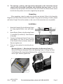
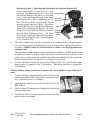
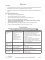
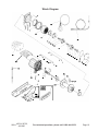
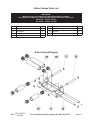
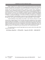
ELECTRIC WINCH
12 VOLT
Models
40764, 93752,
& 91905
ASSEMBLY AND OPERATION INSTRUCTIONS
Model 91905 shown. Due to continuing improvements, actual product may differ slightly from the product described herein.
Distributed Exclusively by Harbor Freight Tools®.
3491 Mission Oaks Blvd., Camarillo, CA 93011
Visit our Web site at http://www.harborfreight.com
To prevent serious injury,
Read and understand all warnings
and instructions before use.
Copyright© 2004, 2006 by Harbor Freight Tools® . All rights reserved. No portion of this manual
or any artwork contained herein may be reproduced in any shape or form without the express
written consent of Harbor Freight Tools.
For technical questions and replacement parts, please call 1-800-444-3353.
Manual revised 07k, 08h
Specifications
Model
Capacity
Cable
Brake
40764
93752
91905
4.1 HP, 8,000 lb.
4.5 HP, 9,000 lb. 4.8 HP, 10,000 lb.
100’ L x 3/8” dia. Galvanized, Aircraft Type
Automatic Load-holding Type
Mounting Pattern
10” x 4.5”
Power In/ Power Out
Handheld Remote Control on 12’ Cable
Hawse
Roller (parts list on page 12)
12 VDC, 650 CCA or more battery
80 lb.
85 lb.
86 lb.
Operation
Fairlead Type
Power Supply
Weight
Sku 40764 - 8,000 lb. capacity
Performance of First Layer
Line Pull and Cable Capacity by Layer
Line Pull
(lb.)
Line Speed
(ft./min)
Amp Draw
Cable Layer
Rated Line Pull
(lb.)
Cable Capacity
(ft.)
0
8.2
35
1
8,000
15
2,000
7.8
100
2
6,335
38
4,000
7.2
180
3
5,243
64
6,000
6.5
230
4
4,473
95
8,000
5
285
5
3,190
100
Sku 93752 - 9,000 lb. capacity
Performance of First Layer
Line Pull and Cable Capacity by Layer
Line Pull
(lb.)
Line Speed
(ft./min)
Amp Draw
Cable Layer
Rated Line Pull
(lb.)
Cable Capacity
(ft.)
0
8.2
35
1
9,000
15
2,000
7.8
100
2
7,300
38
4,000
7.2
180
3
6,200
64
6,000
6.5
230
4
5,400
95
8,000
5
285
5
4,200
100
9,000
4.5
290
Sku 91905 - 10,000 lb. capacity
Performance of First Layer
Line Pull and Cable Capacity by Layer
Line Pull
(lb.)
Line Speed
(ft./min)
Amp Draw
Cable Layer
Rated Line Pull
(lb.)
Cable Capacity
(ft.)
0
8.2
35
1
10,000
15
2,000
7.8
100
2
8,110
38
4,000
7.2
180
3
6,830
64
6,000
6.5
230
4
5,890
95
8,000
5
280
5
5,180
100
10,000
4.5
310
Note: Performance of this winch may vary depending on variations of vehicle’s battery power
and other factors.
REV 06l
SKUs 40764, 93752,
& 91905
For technical questions, please call 1-800-444-3353.
Page 2
Save This Manual
You will need the manual for the safety warnings and precautions, assembly instructions,
operating and maintenance procedures, parts list and diagram. Keep your invoice with this
manual. Write the invoice number on the inside of the front cover. Keep the manual and
invoice in a safe and dry place for future reference.
Safety Warnings and Precautions
WARNING: When using tool, basic safety precautions should always be followed to reduce
the risk of personal injury and damage to equipment.
Read all instructions before using this tool!
1.
Observe work area conditions. Do not use machines or power tools in damp or wet
locations. Don’t expose to rain. Keep work area well lighted. Do not use electrically
powered tools in the presence of flammable gases or liquids.
2.
Keep children away. Children must never be allowed in the work area. Do not let them
handle machines, tools, or extension cords.
3.
Do not force tool. It will do the job better and more safely at the rate for which it was
intended. Do not use inappropriate attachments in an attempt to exceed the tool capacity.
4.
Use the right tool for the job. Do not attempt to force a small tool or attachment to do
the work of a larger industrial tool. Do not use a tool for a purpose for which it was not
intended. Do not use this item for aircraft purposes. Do not exceed winch load
weight capacity for your model (see Specifications on page 2).
5.
Dress properly. Do not wear loose clothing or jewelry as they can be caught in moving
parts. Protective, electrically nonconductive clothes and nonskid footwear are recommended when working. Wear restrictive hair covering to contain long hair.
6.
Use eye protection. Always wear ANSI-approved impact safety goggles. Heavy duty
work gloves need to be worn when handling the cable.
7.
Do not overreach. Keep proper footing and balance at all times. Do not reach over or
across running machines. Do not cross over or under cable under load.
8.
Maintain tools with care. Keep equipment clean for better and safer performance.
Follow instructions for lubricating and changing accessories. Inspect cords periodically
and, if damaged, have them repaired by an authorized technician. The hook must be
kept clean, dry, and free from oil and grease at all times.
9.
Remove adjusting keys and wrenches. Check that keys and adjusting wrenches are
removed from the tool or machine work surface before operating.
10. Avoid unintentional starting. Remove the Switch Ass’y (35) when not in use.
11. Stay alert. Watch what you are doing, use common sense. Do not operate any equipment when you are tired.
12. Check for damaged parts. Before using any tool, any part that appears damaged
should be carefully checked to determine that it will operate properly and perform its
SKUs 40764, 93752,
& 91905
For technical questions, please call 1-800-444-3353.
Page 3
intended function. Check for alignment and binding of moving parts; any broken parts
or mounting fixtures; and any other condition that may affect proper operation. Any part
that is damaged should be properly repaired or replaced by a qualified technician. Do
not use the tool if any switch does not turn On and Off properly. Examine winch before
using. Components may be affected by exposure to chemicals, salts, and rust.
13. Replacement parts and accessories. When servicing, use only identical replacement
parts. Use of any other parts will void the warranty. Only use accessories intended for
use with this tool. Approved accessories are available from Harbor Freight Tools.
14. Do not operate tool if under the influence of alcohol or drugs. Read warning labels
on prescriptions to determine if your judgment or reflexes are impaired while taking drugs.
If there is any doubt, do not operate the tool.
15. Risk of entanglement! Keep hands and body away from Fairlead (cable intake slot)
when operating.
16. Secure vehicle in position before using winch. Block the vehicle’s tires prior to use.
Do not move vehicle with cable attached to a load to pull the load; the cable could
snap.
17. Be certain winch is properly bolted to a structure (or vehicle) that can hold the
winch load.
18. Always use proper couplings when connecting winch cable hook to load. Do not
use inappropriate attachments to extend the length of the winch cable.
19. Do not lift items vertically. The winch was designed for horizontal use only.
20. Never lift people or hoist loads over people.
21. Never come in between the winch and the load when operating.
22. Never fully extend cable while under load. Do not apply load to winch when cable is
fully extended. Keep at least 5 full turns of cable on the drum.
23. When loading a boat into a trailer without keel or side hull rollers, make sure the
trailer is submerged in the water when the boat is loaded by the winch. Attempting to drag the boat on to the trailer while on land can cause winch failure and possible
injury.
24. Never operate winch if cable shows any signs of weakening, is knotted or
kinked.
25. Winch does not have a locking mechanism. Secure load after moving. Do not rely
on the winch to hold it for an extended period.
26. Re-spool cable properly.
27. Make certain that the hook’s safety clasp is shut and the hooks is securely attached to the item to be moved before use.
28. People with pacemakers should consult their physician(s) before use. Electromagnetic fields in close proximity to heart pacemaker could cause pacemaker
interference or pacemaker failure.
SKUs 40764, 93752,
& 91905
REV 07j, 08h
For technical questions, please call 1-800-444-3353.
Page 4
29. The warnings, cautions, and instructions discussed in this instruction manual
cannot cover all possible conditions and situations that may occur. It must be
understood by the operator that common sense and caution are factors which cannot
be built into this product, but must be supplied by the operator.
Unpacking
When unpacking, check to make sure all parts are included. Refer to the Assembly
Diagrams and Parts Lists at the end of this manual. If any parts are missing or broken, please
call Harbor Freight Tools at the number on the cover of this manual as soon as possible.
Installation
1.
Mount the Fairlead (2) to the Mounting Frame
(1) using supplied bolts, nuts, and washers.
2.
Mount Electric Winch to the Mounting Frame
(1) using Bolt (3) and Nut (6). See illustration
to the right.
3.
Connect the Solenoid Output Power Lines
(short-black) (17s, 24s) to either terminal
of the Electric Winch as shown below, left.
Securely tighten nuts.
4.
Winch
Mounting
Frame (1)
Fairlead (2)
There are two options for mounting the solenoid:
Mounting Option 1: Mounting the Solenoid to the Mounting Frame (1)
Mount the Solenoid Assembly (34) to the Mounting Frame (1) using the three
Flat Washers (20s), three Spring Washers (21s), and three Nuts (22s) as shown
below, right. Securely tighten nuts.
So
le
no
id
As
se
m
bl
y
Motor
Terminal
Solenoid
Cable
Fig2
SKUs 40764, 93752,
& 91905
For technical questions, please call 1-800-444-3353.
Page 5
Mounting Option 2: Mounting the Solenoid to the Solenoid Bracket (40)
Remove both Bolts (12) and Nuts (13) from
the Motor End Bearing Ass’y (33). Then align Solenoid
the Solenoid Bracket (40) with the 2 mounting
holes. Attach the Solenoid bracket to the Motor Solenoid
End Bearing Ass’y (33) by reattaching the Tie Bracket
Bars (10) with the Bolts (12) and Nuts (13) that
were previously removed. Tighten. Secure the
Nut
Solenoid Bracket (40) to the Motor End Bearing
Ass’y (33) by attaching the Bracket Tie Down
Strap (41) around both the Solenoid Bracket Bracket
and the Motor End Bearing Ass’y. Pull Strap Tie Down
Strap
until secure. Attach the Solenoid to the bracket
using the Flat Washers (20s), Spring Washers
(21s), and Nuts (22s).
5.
Place the completed Electric Winch assembly at the location where it will be mounted.
Use the remaining holes in the Mounting Frame as a template to mark and drill holes for
mounting. ALWAYS check for electrical wires or cables in the drilling path before
starting to drill.
If the provided hardware does not accommodate the installation, use SAE grade 5 bolts
or higher with torque to 35 ft-lb It should be aligned and secured to a solid part of the
vehicle (front or rear) where the full rated load will be evenly distributed. Also remember
that the Electric Winch is designed for horizontal pull, not vertical.
6.
Connect the Solenoid Assembly red (positive) Battery Cable (13s) to the closest screwdown positive (+) terminal to the 12 volt battery. The battery should be of at least 650
CCA capacity.
Caution: Battery cables should not be drawn taut. Leave slack for some cable movement.
7.
Connect the black (negative) Battery Cable (16s) from the
Solenoid Assembly (34) to the closest screw-down negative (–) terminal to the 12 volt battery.
8.
Disengage the clutch by moving the Cam Ring (11) to the
OUT position.
9.
Pull the Cable (36) through the Fairlead and connect the
Hook and safety pin.
(11)
10. Test Electric Winch for proper operation. Refer to the Operation section, next page.
SKUs 40764, 93752,
& 91905
For technical questions, please call 1-800-444-3353.
Page 6
Operation
1.
Disengage the clutch by moving the Cam Ring (11) to the Out position.
2.
Grab the Cable Assembly (36) hook and pull the cable to the desired length, then attach
to item being pulled. Make certain that the hooks safety clasp is fully closed.
WARNING!: You MUST leave at least five full turns of cable on the drum
at all times. Review Winch Safety Warnings and Precautions starting on
page 3 before continuing. STOP THE WINCH IMMEDIATELY and release
cable with the switch if the cable begins to get entangled on the drum.
(6s)
3.
Reengage the clutch by moving the Cam Ring to the In position.
4.
Lift the Socket Cover (2s) exposing the electrical switch connector.
5.
Insert the Switch Ass’y (35) connector into the Socket (6s).
6.
While standing aside of the pull path, press (and hold) the Red switch on the Switch
Ass’y (35) forward.
Press (and hold) the switch backward to reverse directions. Wait until the motor stops
before reversing directions.
The power out function will puts stress on the winch’s automatic braking system.
IMPORTANT: Do not use the power out function of the winch for more than 10
seconds at a time; it may cause damage to the winch’s brake system.
7.
When the pulling is complete, remove the Switch Assembly from the Socket (6s) and
replace the Socket Cover (2s).
CAUTION: The Electric Winch is designed for intermittent use only, and should not be
used in a constant duty application. The duration of the pulling job should be kept as
short as possible. If the Winch motor becomes very hot to the touch, stop the Winch
and let it cool down for several minutes. Never pull for more than one minute at or near
the rated load. Do not maintain power to the Winch if the motor stalls.
REV 08h
SKUs 40764, 93752,
& 91905
For technical questions, please call 1-800-444-3353.
Page 7
Maintenance
Lubrication
1.
All moving parts within the Electric Winch have been lubricated using high temperature
lithium grease at the factory. No internal lubrication is required.
2.
Lubricate the cable portion of the Cable Assembly (36) periodically using a light penetrating oil.
Cable Assembly Replacement
1.
Move Cam Ring (11) to the OUT position.
2.
Extend Cable Assembly (36) to its full length.
Note how the existing cable is connected to the inside of the drum.
3.
Remove old Cable Assembly and attach new one.
Caution: Do not replace with inferior cable. Always use the approved replacement part from Harbor Freight Tools.
4.
Retract Cable Assembly onto cable drum being careful not to allow kinking.
5.
Cover the Cable Assembly and Electric Winch when not in use.
Troubleshooting
This chart is included as a reference tool for qualified technicians only.
Only a qualified technician should attempt to repair this unit.
SYMPTOM
POSSIBLE CAUSE
SUGGESTED ACTION
Motor does not
turn On
1. Switch Assy not connected
properly
2. Loose battery cable
connections
3. Solenoid malfunctioning
4. Defective Switch Assy
5. Defective motor
6. Water has entered motor
1. Insert Switch Assy all the way into connector
2. Tighten nuts on all cable connections
3. Tap solenoid to loosen contacts. Apply 12 volts to
coil terminals directly. A clicking indicates proper
activation
4. Replace Switch Assy
5. Check for voltage at armature port with Switch
pressed. If voltage is present, replace motor.
6. Allow to drain and dry. Run in short bursts without
load until completely dry
Motor runs but
cable drum does
not turn
Cam Ring (clutch) not engaged
Move the Cam Ring to the In position. If problem
persists, a qualified technician needs to check and
repair
Motor runs slowly
or without normal
power
1. Insufficient current or voltage
2. Loose or corroded battery
cable connections.
1. Battery weak, recharge. Run winch with vehicle
motor running
2. Clean, tighten, or replace
Motor overheating Winch running time too long
Allow winch to cool down periodically
Motor runs in one
direction only
1. Tap solenoid to loosen contacts. Repair or
replace solenoid
2. Replace Switch Assy
1. Defective or stuck solenoid
2. Defective Switch Assy
SKUs 40764, 93752,
& 91905
For technical questions, please call 1-800-444-3353.
Page 8
Parts Lists and Diagrams
Winch Parts List
IMPORTANT!
When ordering parts, reference the appropriate number as follows:
Sku 40764 - 8,000 lb.= 87495
Sku 93752 - 9,000 lb.= 87478
Sku 91905 - 10,000 lb.= 87496
Item
1
Description
Mounting Frame (Box B)
Fairlead
Q’ty
Item
1
22
Cap Screw M6x12
1
23
Gear, intermediate-sun
1
24
Gear, input-sun
1
25
Thrust Disc
1
26
Thrust Washer
3
27
Bushing
2
28
Gasket
1
29
Gear Housing Cover
1
30
Screw M5x12
6
31
Drum
1
32
Brake/shaft assy
1
33
Motor End Bearing Assy
1
34
Solenoid Assy (see parts list S)
1
35
Switch Assy
1
36
Cable Assy Ø3/8” x100’
1
37
Gear Carrier Assy, output
1
38
Gear Carrier Assy, intermediate
1
39
Gear Carrier Assy, input
1
40
Solenoid Bracket
1
41
Bracket Tie-down Strap
1
42
Spring Washer Ø5
1
(Single Piece Hawse for Sku 40764;Roller
Fairlead Assembly for Skus 93752 & 91905
– see Roller Fairlead parts list)
1
3
Screw M10x34
6
6
Nut M10
6
7
End Bearing
1
8
Spring
6
9
Locking Ring
1
10
Tie Bar
2
11
Cam Ring
1
12
Bolt M8 x 30
4
13
Nut M8
4
14
Ring Gear
1
15
Gear Ring Retainer
1
16
Brake Shoe
2
17
Screw M6x20
6
18
Gear Out-sun
1
19
Shaft Bushing
1
20
Roll Pin Ø3x10
1
21
Cable Anchor
1
2
Description
Q’ty
NOTE: Some parts are listed and shown for illustration purposes only
and are not available individually as replacement parts.
PLEASE READ THE FOLLOWING CAREFULLY
THE MANUFACTURER AND/OR DISTRIBUTOR HAS PROVIDED THE PARTS DIAGRAM IN THIS
MANUAL AS A REFERENCE TOOL ONLY. NEITHER THE MANUFACTURER NOR DISTRIBUTOR
MAKES ANY REPRESENTATION OR WARRANTY OF ANY KIND TO THE BUYER THAT HE OR SHE
IS QUALIFIED TO MAKE ANY REPAIRS TO THE PRODUCT OR THAT HE OR SHE IS QUALIFIED TO
REPLACE ANY PARTS OF THE PRODUCT. IN FACT, THE MANUFACTURER AND/OR DISTRIBUTOR
EXPRESSLY STATES THAT ALL REPAIRS AND PARTS REPLACEMENTS SHOULD BE UNDERTAKEN
BY CERTIFIED AND LICENSED TECHNICIANS AND NOT BY THE BUYER. THE BUYER ASSUMES
ALL RISK AND LIABILITY ARISING OUT OF HIS OR HER REPAIRS TO THE ORIGINAL PRODUCT OR
REPLACEMENT PARTS THERETO, OR ARISING OUT OF HIS OR HER INSTALLATION OF REPLACEMENT PARTS THERETO.
SKUs 40764, 93752,
& 91905
REV 07a
For technical questions, please call 1-800-444-3353.
Page 9
Winch Diagram
SKUs 40764, 93752,
& 91905
For technical questions, please call 1-800-444-3353.
Page 10
Roller Fairlead Parts List
IMPORTANT!
When ordering parts, reference the appropriate number as follows:
Sku 40764 uses a single piece hawse fairlead instead, don’t order from this list.
Sku 93752 - 9,000 lb.= 87478
Sku 91905 - 10,000 lb.= 87496
Part
Description
Q’ty
Part
Description
Q’ty
1f
Frame
1
5f
Short Shaft
2
2f
Long Roller
2
6f
Bushing
8
3f
Long Shaft
2
7f
C-clip
8
4f
Short Roller
2
Roller Fairlead Diagram
SKUs 40764, 93752,
& 91905
For technical questions, please call 1-800-444-3353.
Page 11
Solenoid Parts List
IMPORTANT!
When ordering parts, reference the appropriate number as follows:
Sku 40764 - 8,000 lb.= 87495
Sku 93752 - 9,000 lb.= 87478
Sku 91905 - 10,000 lb.= 87496
Item
1s
2s
3s
4s
5s
6s
7s
8s
9s
10s
11s
12s
Description
Plastic Housing
Socket Cover
Flat Washer
Spring Washer
Combination-head Screw M5x10
Socket
Self-tapping Screw F 3x12
Copper Spacer
Combination-head ScrewM5x12
Solenoid
Ground Cable
Screw M6x30
Q’ty
1
1
6
4
4
1
2
1
2
1
1
4
Item
13s
14s
15s
16s
17s
18s
19s
20s
21s
22s
23s
24s
Description
+ Battery Cable (Red)
Base Plate
Nut M8
– Battery Cable (Black)
– Output Cable (Black)
Nut M5
Spacer
Flat Washer
Spring Washer
Nut M6
Fiberglass Sleeve
+ Output Cable (Red)
Q’ty
1
1
4
1
1
2
4
8
8
8
1
1
Solenoid Diagram
8s
9s
10s
11s
12s
13s
14s
15s
16s
17s
18s
19s
20s
21s
22s
For technical questions, please call 1-800-444-3353.
1s 2s 3s 4s5s 6s 7s
24s
24s
SKUs 40764, 93752,
& 91905
Page 12
LIMITED 90 DAY WARRANTY
Harbor Freight Tools Co. makes every effort to assure that its products meet high quality
and durability standards, and warrants to the original purchaser that this product is free from
defects in materials and workmanship for the period of 90 days from the date of purchase. This
warranty does not apply to damage due directly or indirectly, to misuse, abuse, negligence or
accidents, repairs or alterations outside our facilities, criminal activity, improper installation,
normal wear and tear, or to lack of maintenance. We shall in no event be liable for death, injuries to persons or property, or for incidental, contingent, special or consequential damages
arising from the use of our product. Some states do not allow the exclusion or limitation of
incidental or consequential damages, so the above limitation of exclusion may not apply to
you. This warranty is expressly in lieu of all other warranties, express
or implied, including the warranties of merchantability and fitness.
To take advantage of this warranty, the product or part must be returned to us with
transportation charges prepaid. Proof of purchase date and an explanation of the complaint
must accompany the merchandise. If our inspection verifies the defect, we will either repair or
replace the product at our election or we may elect to refund the purchase price if we cannot
readily and quickly provide you with a replacement. We will return repaired products at our
expense, but if we determine there is no defect, or that the defect resulted from causes not
within the scope of our warranty, then you must bear the cost of returning the product.
This warranty gives you specific legal rights and you may also have other rights which
vary from state to state.
3491 Mission Oaks Blvd. • PO Box 6009 • Camarillo, CA 93011 • (800) 444-3353
SKUs 40764, 93752,
& 91905
For technical questions, please call 1-800-444-3353.
Page 13