1
POWER RACK & PINION
2001 Chevrolet Camaro
2000-01 STEERING
Power Rack & Pinion
Cars - Except Prizm & Saturn
MODEL IDENTIFICATION
BODY CODE IDENTIFICATION
Body Code
"C"
"E"
"F"
"G"
"H"
"J"
"K"
"N"
"W"
Model
.................................................... Park Avenue
....................................................... Eldorado
.............................................. Camaro & Firebird
......................................................... Aurora
........................................... Bonneville & LeSabre
............................................. Cavalier & Sunfire
.............................................. DeVille & Seville
....................................... Alero, Grand Am & Malibu
................. Century, Grand Prix, Impala, Intrigue, Lumina,
Monte Carlo & Regal
....................................................... Corvette
"Y"
DESCRIPTION & OPERATION
NOTE:
Some vehicles are equipped with Variable Effort Steering
(VES) system, identified by a solenoid on the power steering
pump at the pressure line outlet. See appropriate ELECTRONIC
article.
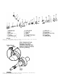
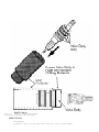
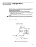
RACK & PINION ASSEMBLY
Pump pressurizes fluid and sends it through the pump’s flow
control valve to the pinion and valve on the rack and pinion assembly.
See Fig. 1. Pinion and valve direct fluid to either side of the piston
and rack, depending on turning direction of steering wheel. Piston and
rack converts hydraulic pressure into linear force, reducing turning
effort.
POWER STEERING PUMP
Two types of power steering pumps are used, CB series or TC
series. These pumps are constant displacement vane-type pumps. See
Fig. 4 and Fig. 5. When pressure exceeds set limits, a flow control
pressure relief valve opens, allowing fluid to return to the inlet
side of the pump. Some pump applications have remote fluid reservoirs
or reservoir attached to pump assembly, to enable different pump
mounting locations. Some models have a reverse rotation pump,
depending upon location and belt routing.
LUBRICATION
FLUID TYPE
Use GM Power Steering Fluid (1050017). Failure to use proper
fluid will cause hose and seal damage, resulting in fluid leaks and
damage to pump and/or rack and pinion assembly.
CAPACITY
POWER STEERING FLUID CAPACITY
Application
All Models
Pump Capacity
............
1.0 Pt. (0.5L)
System Capacity
.........
1.5 Pts. (0.75L)
FLUID LEVEL CHECK
Fluid level is indicated by marks on reservoir or dipstick.
Ensure fluid
level
is at FULL COLD mark when fluid temperature is
about 70 F (21 C). Ensure fluid level is at FULL
HOT mark when fluid
is at operating temperature of about 170 F (77 C).
HYDRAULIC SYSTEM BLEEDING
NOTE:
If air is introduced into hydraulic system during servicing,
bleed system. Aerated fluid, which appears Light Tan in
color, results in poor steering performance and may cause
pump damage.
1) Turn ignition off. Raise and support vehicle with wheels
off ground. Turn wheels fully to left. Add power steering fluid to
FULL COLD mark on dipstick. Leave cap off. Turn wheels from side to
side several times, but DO NOT touch steering stops. Add fluid, if
necessary, to maintain level at FULL COLD mark.
2) Start engine. With engine idling, recheck fluid level. Add
fluid, if necessary, to bring level to FULL COLD mark. Install cap.
Return wheels to center position. Lower vehicle. Continue to run
engine for 2-3 minutes. Road test vehicle. Check for leaks. Ensure
fluid level is at FULL HOT mark when fluid stabilizes at operating
temperature.
ADJUSTMENTS
POWER STEERING PUMP BELT (SERPENTINE BELT)
1) On most applications, serpentine belt tension is
maintained by automatic tensioner and no adjustment is necessary.
Ensure tensioner indicator mark, on movable portion of tensioner, is
within limits of slotted area on stationary portion of tensioner. Any
reading outside these limits indicates a worn belt or defective
tensioner.
2) If installing NEW belt, ensure tensioner indicator is
within limit marks. If installing original belt, ensure belt operating
length and/or tensioner operating range marks are not out of limits.
Replace belt or tensioner as necessary. See appropriate SERVICE &
ADJUSTMENT SPECIFICATIONS article in ENGINE PERFORMANCE.
RACK BEARING PRELOAD
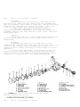
1) Raise and support vehicle. Turn front wheels to straightahead position. Loosen adjuster plug lock nut. See Fig. 1. Turn
adjuster plug clockwise until it bottoms in housing. Back off adjuster
plug 50-70 degrees (about one flat).
2) While holding adjuster plug stationary, tighten adjuster
plug lock nut to specification. See TORQUE SPECIFICATIONS. Test drive
vehicle, ensuring steering wheel returns to center after turning.
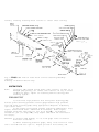
Fig. 1: Exploded View Of Power Rack & Pinion Steering Assembly
(Typical)
Courtesy of General Motors Corp.
SYSTEM TESTS
NOTE:
Incorrect idle speed, fluid level, belt tension, as well as a
damaged pump pulley, can affect test results. If any of these
conditions exist, repair as necessary before testing power
steering system.
PRESSURE TEST
1) Disconnect high pressure line from power steering pump.
Connect power steering pressure tester gauge between high pressure
line and power steering pump using appropriate adapters. Completely
open tester valve.
2) Run engine until fluid reaches operating temperature. Stop
engine. Check fluid level. Add fluid if necessary.
Start engine.
Pressure should be less than 230 psi (16.8 kg/cm ). If pressure
exceeds 230 psi (16.8 kg/cm ), stop engine and check for restriction
in hose(s).
CAUTION: To prevent pump damage, Do not hold gauge valve closed for
more than 5 seconds.
3) While observing pressure gauge, fully close valve for less
than 5 seconds and then open it. Repeat process 2 more times, and
record highest pressure displayed each time valve is closed. If
readings are as specified and within 50 psi (4 kg/cm ) of each other,
go to step 6). See PRESSURE RELIEF SPECIFICATIONS
table. If readings
are as specified but not within 50 psi (4 kg/cm ) of each other, go to
next step.
If readings are not as specified but within 50 psi (4
kg/cm ) of each other, go to step 5).
PRESSURE RELIEF SPECIFICATIONS
Application
psi ( kg/cm )
"C" & "H" Bodies ..................... More Than 1350 (95)
"E" Body ............................ More Than 1500 (105)
"F" Body ............................. More Than 1200 (84)
"G" & "K" Bodies .................... More Than 1700 (120)
"J" Body
2.2 L .............................. More Than 1200 (84)
2.4 L .............................. More Than 1300 (91)
"N" Body ............................. More Than 1400 (98)
"W" Body ............................. More Than 1300 (91)
"Y" Body ............................. More Than 1250 (89)
4) Check for sticking flow control valve. Remove valve, but
DO NOT disassemble. Clean valve using crocus cloth or fine hone. Flush
system, if dirty. Install valve and retest system. If readings are now
as specified, go to step 6). If reading are not as specified, go to
next step.
5) Replace flow control valve and retest system. If pressure
readings are still low, check pump rotor and vanes for wear. Replace
complete pump assembly if worn and flush power steering system. If
pressure readings are as specified, go to step 7).
6) With valve open, turn steering wheel from stop to stop.
Record highest pressure with wheels at both stops. If highest pressure
is not equal to highest pressure recorded in step 3), rack and pinion
assembly is leaking internally. Repair or replace assembly. If
pressures are equal, no problem exists. Go to next step.
7) Turn engine off. Remove tester. Reconnect high pressure
hose to pump. Check fluid level. Bleed hydraulic system. See
HYDRAULIC SYSTEM BLEEDING under LUBRICATION.
FLOW RATE TEST
1) Connect Power Steering Analyzer (J-44721) into system.
Fully open analyzer valve. Run engine until fluid reaches normal
operating temperature. Check fluid level. Add fluid if necessary.
Record pressure and flow rate.
2) Close valve partially until pressure is 700 psi (49
kg/cm ), and then record flow rate. Subtract flow rate from that
measured in step 1). If flow rate drops more than one gallon (3.8L)
per minute, replace ring, rotor and vanes in pump. If flow rate does
not drop one gallon (3.8L) per minute, go to next step.
3) Increase engine speed to 1500 RPM, and record flow rate.
Subtract flow rate from that measured in step 1). If difference
between flow rates is more than one gallon (3.8L) per minute, remove
and clean flow control valve. If not, go to next step.
4) Turn steering wheel from stop to stop. Flow rate should be
less than one gallon (3.8L) per minute at each stop. If flow rate is
not as specified, check rack and pinion assembly for leakage.
5) Turn engine off. Remove tester. Reconnect high pressure
hose to pump. Check fluid level. Bleed hydraulic system. See
HYDRAULIC SYSTEM BLEEDING under LUBRICATION.
REMOVAL & INSTALLATION
CAUTION: When battery is disconnected, vehicle computer and memory
systems may lose memory data. Driveability problems may exist
until computer systems have completed a relearn cycle. See
COMPUTER RELEARN PROCEDURES article in GENERAL INFORMATION
before disconnecting battery.
OUTER TIE ROD
Removal
Raise and support vehicle. Remove cotter pin and castle nut
from outer tie rod end. Loosen outer-to-inner tie rod lock nut. Using
Steering Linkage Puller (J-24319-01), separate outer tie rod end from
steering knuckle. Remove outer tie rod end from inner tie rod, noting
number of turns required to remove.
Installation
Install outer tie rod end with same number of turns as when
removed. Tighten outer-to-inner tie rod lock nut to specification. See
TORQUE SPECIFICATIONS. To complete installation, reverse removal
procedure. Tighten tie rod end castle nut to specification. Install
NEW cotter pin at castle nut. DO NOT back off nut to install cotter
pin. Adjust toe-in as necessary.
RACK & PINION BOOTS
Removal
Remove outer tie rod. See OUTER TIE ROD. Remove outer-toinner tie rod lock nut. Remove outer boot clamp. Cut off and discard
inner boot clamp. When replacing both rack boots, mark location of
breather tube to rack (if equipped), for installation reference.
Remove breather tube. DO NOT remove breather tube if only replacing
one boot. Slide boot from inner tie rod.
Installation
1) Place NEW inner clamp onto boot. Install breather tube (if
removed), aligning tube as marked during removal. Install boot. If
necessary, apply thin coat of grease onto inner tie rod shaft (except
threads) and boot clamping area onto housing to aid in installation.
Ensure boot is not twisted or out of shape. Ensure breather tube is in
proper notch position in boot.
2) Crimp inner clamp using Banding Tool (J-22610). Install
outer clamp. Install outer tie rod end. Tighten outer-to-inner tie rod
lock nut to specification. See TORQUE SPECIFICATIONS. To complete
installation, reverse removal procedure. Adjust toe-in as necessary.
POWER STEERING PUMP PULLEY
Removal
It may be necessary to remove or reposition power steering
pump to remove pulley. If necessary, see POWER STEERING PUMP. Install
Pulley Remover (J-25034), on pulley hub at pump shaft. While holding
remover body with wrench, turn center bolt clockwise to draw/pull
pulley off pump shaft.
Installation
NOTE:
Do not use arbor press to install pulley.
Using Pulley Installer (J-25033), install pulley onto shaft
until internal stop is contacted or face of pulley hub is even with
end of shaft. To complete installation, reverse removal procedure.
Fill and bleed hydraulic system. See HYDRAULIC SYSTEM BLEEDING under
LUBRICATION.
POWER STEERING PUMP
NOTE:
When replacing power steering pump, ensure proper replacement
pump is installed.
Removal & Installation (Except "F" Body 5.7L)
1) Disconnect negative battery cable. Remove serpentine belt.
Place a drain pan under vehicle. Remove or reposition, as necessary,
coolant reservoir and power steering pump pulley. See
POWER STEERING PUMP PULLEY.
2) Remove air cleaner housing, (if necessary). Remove
pressure and return hoses from pump. On "W" and "G" bodies, remove
fuel injector site shield. Remove ABS wiring harness and bracket (if
equipped). On "C" body remove right outer tie rod using Tie Rod
Remover (J-24319-01). See OUTER TIE ROD. Remove pump mounting bolts.
Remove pump.
3) To install, reverse removal procedure. Fill and bleed
hydraulic system. See HYDRAULIC SYSTEM BLEEDING under LUBRICATION.
Removal & Installation ("F" Body 5.7L)
1) Remove pump pulley (if necessary). See
POWER STEERING PUMP PULLEY. Remove pressure and return hoses from
pump.
2) Remove pump mounting bolts. Remove front bracket. Remove
pump assembly from rear bracket.
3) To install, reverse removal procedure. Fill and bleed
hydraulic system. See HYDRAULIC SYSTEM BLEEDING under LUBRICATION.
Fill and bleed engine cooling system. See appropriate article in
ENGINE COOLING.
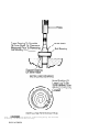
PUMP FLOW CONTROL VALVE ASSEMBLY
Removal & Installation
Remove power steering pump (if necessary to access rear of
pump). See POWER STEERING PUMP. Remove pressure line fitting (or VES
actuator) from pump. See Fig. 2. Remove "O" ring, flow control valve
assembly and flow control spring. To install, reverse removal
procedure. Tighten pressure line fitting to specification. See
TORQUE SPECIFICATIONS.
Fig. 2: Exploded View Of Flow Control Valve Assembly (Typical)
Courtesy of General Motors Corp.
PUMP SHAFT SEAL
Removal (CB Series Pump)
Remove power steering pump (if necessary to allow clearance
for pulley removal). See POWER STEERING PUMP. Remove pump pulley. See
POWER STEERING PUMP PULLEY. Protect pump shaft with shim stock. Use
care not to damage pump shaft surface. Cut seal metal housing with
small chisel to ease seal removal. Use screwdriver to pry seal out of
body. Remove and discard seal. Remove shim stock from shaft.
Installation
Lubricate new seal with power steering fluid. Using Shaft
Seal Installer (J-7728) or a suitable size deep socket, drive seal
into housing until it bottoms. Install pulley onto pump. See
POWER STEERING PUMP PULLEY. Install pump onto bracket (if removed).
Removal (TC Series Pump)
Remove power steering pump (if necessary to allow clearance
for pulley removal). See POWER STEERING PUMP. Remove pump pulley. See
POWER STEERING PUMP PULLEY. Remove bearing retaining ring. Removal
drive shaft and bearing assembly. Use screwdriver to pry seal out of
body. Remove and discard seal. If replacing bearing, measure clearance
(if any) between drive shaft shoulder and bearing inner race. See
Fig. 6.
Installation
Lubricate new seal with power steering fluid. Using suitable
size deep socket, drive seal into housing until it bottoms. Press
bearing onto shaft to clearance measured before removal. Install shaft
and bearing into housing, rotating assembly to engage rotor. Install
bearing retaining ring with beveled side down, indicated by position
of large lug on ring. See Fig. 7. Install pulley onto pump. Install
pump onto bracket (if removed).
RACK & PINION ASSEMBLY
CAUTION: To prevent damage to Supplemental Inflatable Restraint (SIR)
system, place front wheels in a straight-ahead position and
turn ignition switch to the LOCK position.
Follow these precautions (if applicable), when removing rack
and pinion from vehicle:
*
*
*
*
*
Before disconnecting battery, see COMPUTER RELEARN
PROCEDURES in GENERAL INFORMATION.
Disconnect steering column coupler before lowering
engine frame.
DO NOT allow rear of engine frame to hang, always support
frame.
DO NOT allow steering column to rotate when rack and
pinion is removed, damage to SIR system.
DO NOT start engine with power steering hoses removed.
Serious pump damage may result.
Removal (Except "E", "F" & "Y" Bodies)
1) Install Steering Column Lock Pin (J-42640) into steering
column, (if equipped). Disconnect battery. Raise and support vehicle.
Remove front wheels. Separate outer tie rod ends. See OUTER TIE ROD.
Remove steering column-to-rack coupler pinch bolt.
2) If exhaust system interferes with removal, remove front
portion of exhaust system. Remove any heat shields. Disconnect any
electrical connectors or components as necessary. Disconnect sway bar
if needed. On Eldorado, remove road sensing suspension links.
3) Loosen front engine frame-to-body mounting bolts about one
turn, but DO NOT remove. Install jack under rear portion of engine
frame, and remove rear engine frame-to-body mounting bolts. Ensure
rear of engine frame can be lowered without damaging other components.
Separate steering coupler from rack and pinion. On Eldorado, remove
transaxle mount. Using jack, lower rear end of engine frame.
4) Place a drain pan under rack and pinion. Remove power
steering pressure and return lines from rack and pinion assembly.
Remove rack and pinion mounting bolts and bushings. Remove rack and
pinion from vehicle through left wheel opening on most models.
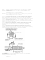
Installation
To install, reverse removal procedures. Tighten nuts and
bolts to specifications. Apply Loctite to threads and tighten in
sequence. See Fig. 3. See TORQUE SPECIFICATIONS. Fill and bleed
hydraulic system. See HYDRAULIC SYSTEM BLEEDING under LUBRICATION.
Adjust toe-in as necessary. See appropriate SPECIFICATIONS &
PROCEDURES article in WHEEL ALIGNMENT.
Removal ( "E" Body)
1) Disconnect battery. Raise and support vehicle. Remove
front wheels. Remove power steering pressure hoses from rack and
pinion. Separate outer tie rod ends. See OUTER TIE ROD. Remove
steering column-to-rack coupler pinch bolt.
2) Support front suspension crossmember with a suitable jack.
Remove brake pipes from the retainers on the front suspension support.
Remove front suspension crossmember mounting bolts. Lower front
suspension crossmember in order to remove rack and pinion. Remove rack
and pinion mounting bolts. Remove rack and pinion from front
suspension crossmember.
Installation
To install, reverse removal procedures. Tighten nuts and
bolts to specifications. Apply Loctite to threads and tighten in
sequence. See TORQUE SPECIFICATIONS. Fill and bleed hydraulic system.
See HYDRAULIC SYSTEM BLEEDING under LUBRICATION. Adjust toe-in as
necessary. See appropriate SPECIFICATIONS & PROCEDURES article in
WHEEL ALIGNMENT.
Removal ("F" Body)
1) Disconnect negative battery cable. Remove serpentine belt,
(if needed). On (V8), remove air intake resonator. On all models,
place drain pan under vehicle and drain power steering fluid. Raise
and support vehicle. Remove front wheels. Support engine with suitable
jack. Disconnect power steering pressure and return hoses from rack
and pinion assembly.
2) Remove steering coupler pinch bolts and remove coupler
from rack and pinion. Disconnect and separate front tie rod ends. See
OUTER TIE ROD. On (V8), remove generator. On (V8), remove left-side
engine mount through-bolt. On all models, remove rack and pinion
mounting bolts and nuts. Remove rack and pinion.
Installation
To install, reverse removal procedures. Tighten nuts and
bolts to specification. See TORQUE SPECIFICATIONS. Fill and bleed
hydraulic system. See HYDRAULIC SYSTEM BLEEDING under lubrication.
Adjust toe-in as necessary. See appropriate SPECIFICATIONS &
PROCEDURES article in WHEEL ALIGNMENT.
Removal ("Y" Body)
1) Disconnect negative battery cable. Remove brake pressure
modulator valve (BPMV) bracket. Place drain pan under vehicle and
drain P/S fluid. Remove intermediate shaft shield. Disconnect power
steering pressure and return hoses from rack and pinion assembly.
Disconnect power steering cooler and remove from vehicle. Remove
steering coupler pinch bolts and remove coupler from rack and pinion.
2) Raise and support vehicle. Remove front wheels. Disconnect
and separate front tie rod ends. See OUTER TIE ROD. Disconnect
electrical connectors. Remove stabilizer bar from crossmember.
Disconnect brake pipe from crossmember fastener clips. Remove rack and
pinion mounting bolts and nuts. Using hand tools only, LOOSEN, DO NOT
remove, four crossmember mounting nuts. Remove power rack and pinion
through left wheelwell opening by rotating.
Installation
To install, reverse removal procedure. Tighten nuts and bolts
to specification. See TORQUE SPECIFICATIONS. Fill and bleed hydraulic
system. See HYDRAULIC SYSTEM BLEEDING under lubrication. Adjust toe-in
as necessary. See appropriate SPECIFICATIONS & PROCEDURES article in
WHEEL ALIGNMENT.
Fig. 3: Mounting Bolt Tightening Sequence
Courtesy of General Motors Corp.
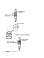
OVERHAUL
POWER STEERING PUMP (CB SERIES)
NOTE:
Pump is not serviceable on Seville.
Disassembly
1) Remove hydraulic union fitting (or VES actuator) from
pump. See Fig. 4. Remove "O" ring, flow control valve assembly and
flow control spring. Insert punch in access hole, and remove end cover
retaining ring. Press gently on pulley end of shaft to remove end
cover, "O" ring, pressure plate spring and pressure plate.
2) Remove shaft subassembly consisting of remaining
components. Disassemble subassembly, noting component location for
reassembly reference. Cut shaft seal with a small chisel. Remove and
discard shaft seal.
Inspection
Inspect pump ring, rotor, vanes, thrust plate, pressure plate
and shaft for scoring, pitting or chatter marks. Replace worn or
damaged parts.
Reassembly
1) Lubricate new shaft seal, "O" rings and all other
components with power steering fluid. Drive new seal into housing with
suitable socket. Assemble shaft subassembly with components in
original locations. Ensure counterbore in center of pump rotor faces
pump pulley.
2) Install shaft subassembly. Install remaining components.
Press end cover in far enough to snap retaining ring into place.
Install flow control valve assembly and related components. Tighten
hydraulic union to specification. See TORQUE SPECIFICATIONS.
Fig. 4: Exploded View Of Power Steering Pump (CB Series)
Courtesy of General Motors Corp.
POWER STEERING PUMP (TC SERIES)
NOTE:
Pump is not serviceable on Seville.
Disassembly
1) Remove pump pulley. See POWER STEERING PUMP PULLEY under
REMOVAL & INSTALLATION. Remove shaft bearing retaining ring. See
Fig. 5. Pull shaft and bearing assembly out of pump. If removing
bearing from shaft, measure and record clearance (if any) between
shaft shoulder and bearing inner race. See Fig. 6. Pry shaft seal from
housing.
2) Remove flow control fitting from pump. See Fig. 5. Remove
"O" ring, flow control valve assembly and flow control spring.
3) Insert small punch in access hole, and remove thrust plate
retaining ring. Using a press and 5/8" piece of bar stock, press
against pressure plate hub until thrust plate is removed. Remove "O"
ring, pump ring, pump rotor, vanes and 2 dowel pins.
4) Remove pressure plate using press (if necessary). Remove
"O" ring from pressure plate. Remove dowel pin from housing. Remove
"O" ring from sleeve. Working from pulley side of housing, drive out
sleeve with a punch.
Inspection
Clean all parts in power steering fluid. Inspect pressure
plate, vanes, pump ring, drive shaft and bearing for scoring, pitting
or chatter marks. Replace worn or damaged parts.
Reassembly
1) Press new sleeve assembly into housing. Install new,
lubricated "O" ring into groove in sleeve. Install dowel pin into
housing. Install pressure plate spring. Install new, lubricated "O"
ring into groove in pressure plate.
2) Mark spot on top of pressure plate directly over dowel pin
hole in plate to help align hole with dowel pin. Install pressure
plate into housing, ensuring pin engages hole in pressure plate.
Install 2 pump ring dowel pins.
3) Install pump rotor with counterbore (larger diameter of
center bore) facing pulley end of housing. Insert pump vanes into
rotor slots. With identification marks on pump ring facing upward,
install pump ring over dowel pins. Install new, lubricated "O" ring
into housing groove.
4) Install thrust plate, ensuring dimples in thrust plate
align with mounting holes in housing, and thrust plate holes engage
pump ring dowel pins. Press thrust plate into housing far enough to
install retaining ring. Install retaining ring with opening centered
on mounting boss nearest access hole.
5) Press shaft bearing onto shaft until clearance between
inner race and shoulder is same as clearance recorded during removal.
See Fig. 7. Slide shaft and bearing assembly into housing, rotating
assembly to align splines of shaft and rotor. Install bearing
retaining ring with beveled side down, indicated by position of large
lug on ring. Install pulley on pump.
Fig. 5: Exploded View Of Power Steering Pump (TC Series)
Courtesy of General Motors Corp.
Fig. 6: Measuring Shaft Bearing Clearance (TC Series)
Courtesy of General Motors Corp.
Fig. 7: Installing Bearing & Retaining Ring (TC Series)
Courtesy of General Motors Corp.
RACK & PINION
NOTE:
Perform overhaul procedures with rack and pinion assembly
removed from vehicle. See RACK & PINION ASSEMBLY under
REMOVAL & INSTALLATION.
Disassembly (Pinion & Valve Assembly)
CAUTION: Do not hammer end of stub shaft, as drive pin on pinion and
valve assembly will loosen or break.
1) Remove adjuster plug lock nut, adjuster plug, adjuster
spring and rack bearing. See Fig. 1. Remove retaining ring from stub
shaft. Remove dust cover from bottom of pinion and valve assembly
housing. While holding stub shaft stationary with 14-mm wrench, remove
lock nut from bottom of shaft.
2) Center rack in housing. For reassembly reference, mark
location of stub shaft notch on housing, and measure distance between
ends of tie rod boot. See Fig. 8.
3) Using an arbor press, press threaded end of pinion and
valve assembly until assembly is loosened, but DO NOT remove. Mark
second location of stub shaft notch on housing for reassembly
reference.
4) Remove stub shaft dust seal, stub shaft seal and stub
shaft bearing annulus (race) assembly. Remove pinion and valve
assembly with retaining ring and valve body rings attached. Carefully
remove valve body rings from pinion and valve assembly.
Fig. 8: Marking Housing & Measuring Tie Rod Boot For Reassembly
Reference
Courtesy of General Motors Corp.
Inspection
Clean valve body ring grooves. Check pinion and valve
assembly drive pin. If pin is broken, replace rack and pinion
assembly.
Reassembly
1) Apply grease to ring grooves. See Fig. 9. Install new
valve body rings on pinion and valve assembly, ensuring split tabs are
engaged and staggered. Use care not to cut rings during installation.
Apply grease to valve body rings.
2) Install pinion and valve assembly into Ring Protector (J37090). See Fig. 10. Position valve assembly in ring protector so
valve body is even with bottom of protector. Allow rings to rest
inside ring protector for about 3 minutes so valve rings will size
properly.
3) Using measurement taken during disassembly as a guide,
center rack in housing. Clean and apply grease to housing bore. Ensure
stub shaft bearing annulus (race) is not damaged and bearing is even
with annulus.
4) Align notch on valve stub shaft with second mark made
during disassembly. Using ring protector and Pinion Seal Installer (J29822), push pinion and valve assembly into housing bore. DO NOT
hammer or use excessive force. If assembly does not fully seat in
housing, ensure valve body rings are not binding in bore.
5) After assembly is seated in bore, ensure notch in stub
shaft and first mark on housing are aligned. While holding stub shaft
to prevent damage to pinion teeth, install adjuster plug lock nut and
tighten to specification. See TORQUE SPECIFICATIONS.
6) Install dust cover. Install stub shaft bearing annulus
assembly onto pinion and valve stub shaft. Install Seal Protector (J29810) onto valve stub shaft. Apply a small amount of grease between
stub shaft seal and stub shaft dust seal. Install seals over protector
and into housing. Install retaining ring into groove in housing.
7) Lubricate stub shaft and dust seal area with grease. Coat
rack bearing, adjuster spring and adjuster plug with grease and
install into housing. With rack centered in housing, turn adjuster
plug clockwise until it bottoms in housing, then back off 50-70
degrees (about one flat). Using an INCH-lb. torque wrench, check
pinion torque. Maximum pinion preload torque is 16 INCH lbs. (1.8 N.
m).
8) Install adjuster plug lock nut onto adjuster plug. While
holding adjuster plug, tighten lock nut to specification. Install rack
and pinion assembly. Fill and bleed system. See
HYDRAULIC SYSTEM BLEEDING under LUBRICATION.
Fig. 9: Installing Valve Body Rings
Courtesy of General Motors Corp.
Fig. 10: Setting Valve Body Rings
Courtesy of General Motors Corp.
INNER TIE ROD
Disassembly
1) Remove outer tie rod end from inner tie rod, noting number
of turns required for removal. Remove hex jam nut from inner tie rod.
Remove adjusting nut from inner tie rod. Remove outer boot clamp. Cut
off and discard inner boot clamp. Mark location of breather tube (if
equipped) for reassembly reference. Slide boot from inner tie rod.
2) Slide shock damper ring on inner tie rod assembly back
toward rack. Place a wrench on flat side of rack to prevent turning.
Place another wrench on flats of inner tie rod. Rotate inner tie rod
counterclockwise until it separates from piston and rack. On "C", "F",
"N" and "Y" bodies, clean old Loctite from threads of rack and inner
tie rod. Remove shock damper ring.
Reassembly
1) Install shock damper ring. To prevent internal damage,
hold rack with a backup wrench during tie rod installation. Apply
Loctite No. 262 to inner tie rod threads. Install inner tie rod onto
rack. Tighten inner tie rod to specification. See
TORQUE SPECIFICATIONS. Stake tie rod fittings as shown in
illustration. See Fig. 11.
2) Ensure inner tie rod pivots freely in all directions, and
then stake both sides of inner tie rod to flats on rack. See Fig. 11.
Ensure both stakes are okay by inserting a .010" (.25 mm) feeler gauge
between rack and tie rod housing. Feeler gauge must not pass between
rack and housing stakes.
3) To complete reassembly, reverse disassembly procedure.
Apply grease to inner tie rod and housing before installing boots.
Install outer tie rod end with same number of turns as when removed.
Install new cotter pin at castle nut. DO NOT back off castle nut to
install cotter pin. Adjust toe-in as necessary. See appropriate
SPECIFICATIONS & PROCEDURES article in WHEEL ALIGNMENT. Fill and bleed
hydraulic system. See HYDRAULIC SYSTEM BLEEDING under LUBRICATION.
Fig. 11: Staking & Inspecting Inner Tie Rod
Courtesy of General Motors Corp.
TORQUE SPECIFICATIONS
TORQUE SPECIFICATIONS
Application
Ft. Lbs. (N.m)
Adjuster Plug Lock Nut
Magnasteer ............................................... 50 (68)
Quiet Valve .............................................. 55 (75)
Crossmember Bolts
"J" & "Y" Bodies ........................................ 81 (110)
Engine Frame-To-Body Bolts
"C", "E", "H", & "K" Bodies ...................... ( 2) 141 (191)
"W" Body ......................................... ( 1) 133 (180)
Engine Mount Bolt ("F" Body) ............................... 37 (50)
Inner Tie Rod-To-Rack ................................. ( 2) 74 (100)
Pinion & Valve Assembly Lock Nut ........................... 26 (35)
Pressure Line Fitting (Hydraulic Union) .................... 20 (27)
Pump Mounting Bolts
"C" & "H" Bodies ......................................... 20 (27)
"E" Body ................................................. 35 (47)
"F" Body ................................................. 23 (31)
"G", "N" & "W" Bodies .................................... 25 (34)
"H" Body ................................................. 20 (27)
"J" Body
2.2 L .................................................. 22 (30)
2.4 L .................................................. 19 (26)
"K" Body
2000 ................................................... 24 (33)
2001 ................................................... 37 (50)
"Y" Body ............................................... 18 (25)
Rack & Pinion Mounting Bolt/Nuts
"C" Body ............................................. ( 2) 48 (65)
"E" Body ............................................. ( 2) 50 (68)
"F" Body ............................................. ( 2) 63 (85)
"G", "H" & "K" Bodies ................................ ( 2) 70 (95)
"J" Body ............................................ ( 2) 89 (120)
"N" Body ............................................ ( 2) 81 (110)
"W" Body ............................................. ( 2) 59 (80)
"Y" Body ............................................ ( 2) 74 (100)
Steering Shaft Lower Coupling Pinch Bolt
All Others ............................................... 35 (47)
"H" & "K" Bodies ......................................... 33 (45)
"J" Body ................................................. 30 (40)
"N" Body ................................................. 15 (20)
Tie Rod Adjusting Hex Lock Nut
All Others ............................................... 50 (68)
"C", "G", & "J" Bodies ................................... 55 (75)
"Y" Body ................................................. 44 (60)
Tie Rod End Castle Nut ................................. ( 3) (4) (5)
Transmission Mounting Nut ("F" Body) ....................... 37 (50)
Wheel Lug Nuts ........................................... 100 (136)
(1) - Install NEW bolts whenever bolts are loosened or removed.
(2) - Apply Loctite (GM 1052624) to bolt threads. Tighten bolts
in sequence. See Fig. 3.
(3) - To align cotter pin holes, tighten nut a minimum of 35
ft. lbs. (47 N.m) and a maximum of 52 ft. lbs. (71 N.m). DO NOT
back off nut to align cotter pin holes.
(4) - On "W" body, tighten to 22 ft. lbs. (30 N.m), then an
additional 115 degrees.
(5) - On "N" body, tighten to 15 ft. lbs. (20 N.m), then an
additional 180 degrees.