1
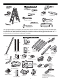
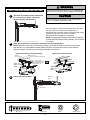
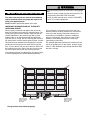
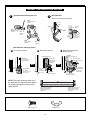
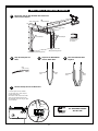
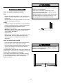
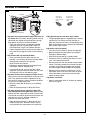
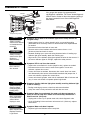
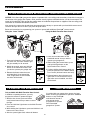
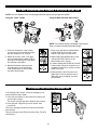
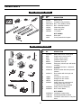
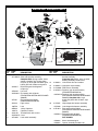
The Chamberlain Group, Inc.
845 Larch Avenue
Elmhurst, Illinois 60126-1196
www.chamberlain.com
GARAGE DOOR OPENER
ASSEMBLY/INSTALLATION MANUAL
■
■
■
■
■
Please read this manual and the enclosed safety materials carefully!
Fasten the manual near the garage door after installation.
The door WILL NOT CLOSE unless the Protector System® is connected
and properly aligned.
Periodic checks of the opener are required to ensure safe operation.
The model number label is located under the light lens on the front panel of
your opener.
PD210D • PD212D
248730
PD610D • PD612D • 7920KD
PD612KLD • 48930D
There are two types of garage door openers pictured. Yours may appear slightly different.
IMPORTANT SAFETY NOTES
This garage door opener has been designed and tested to offer safe service provided it is installed, operated,
maintained and tested in strict accordance with the instructions and warnings contained in this manual.
WARNING
Mechanical
CAUTION
WARNING
WARNING
Electrical
WARNING
CAUTION
When you see these Safety Symbols and Signal Words on
the following pages, they will alert you to the possibility of
serious injury or death if you do not comply with the
warnings that accompany them. The hazard may come
from something mechanical or from electric shock. Read
the warnings carefully.
WARNING
WARNING
WARNING
When you see this Signal Word on the following pages, it
will alert you to the possibility of damage to your garage
door and/or the garage door opener if you do not comply
with the cautionary statements that accompany it. Read
them carefully.
WARNING
TABLE OF CONTENTS
Preparing Your Garage Door . . . . . . . . . . . . . . . . . . . . . 2
Completed Installation . . . . . . . . . . . . . . . . . . . . . . . . . . 3
Tools Needed. . . . . . . . . . . . . . . . . . . . . . . . . . . . . . . . . . 4
Opener Contents. . . . . . . . . . . . . . . . . . . . . . . . . . . . . . . 4
Assembly Hardware . . . . . . . . . . . . . . . . . . . . . . . . . . . . 5
Installation Hardware . . . . . . . . . . . . . . . . . . . . . . . . . . . 5
Assembly . . . . . . . . . . . . . . . . . . . . . . . . . . . . . . . . . . . 6-8
Installation
Installation safety instructions. . . . . . . . . . . . . . . . . . . . . . 9
Install the header bracket . . . . . . . . . . . . . . . . . . . . . . . . 10
Mount the header bracket . . . . . . . . . . . . . . . . . . . . . . . . 11
Position and hang motor unit . . . . . . . . . . . . . . . . . . . . . 12
Fasten the door bracket . . . . . . . . . . . . . . . . . . . . . . . . . 13
Attach door to trolley. . . . . . . . . . . . . . . . . . . . . . . . . . . . 14
Installing the door control . . . . . . . . . . . . . . . . . . . . . . . . 15
Installing the light bulb(s) . . . . . . . . . . . . . . . . . . . . . . . . 16
Electrical requirements . . . . . . . . . . . . . . . . . . . . . . . . . . 16
Install the Protector System® . . . . . . . . . . . . . . . . . . . 17-18
Wire safety sensor . . . . . . . . . . . . . . . . . . . . . . . . . . . . . 19
Adjustment
Adjust the UP and DOWN travel limits . . . . . . . . . . . . . . 20
Adjust the forces . . . . . . . . . . . . . . . . . . . . . . . . . . . . . . . 21
Test the safety reversal system . . . . . . . . . . . . . . . . . . . 22
Test the Protector System® . . . . . . . . . . . . . . . . . . . . . . . 22
Operation
Important Safety Information . . . . . . . . . . . . . . . . . . . . . 23
Using your garage door opener . . . . . . . . . . . . . . . . . . . 23
Using the wall-mounted door control . . . . . . . . . . . . . . . 24
Care of your opener . . . . . . . . . . . . . . . . . . . . . . . . . . . . 24
To open the door manually . . . . . . . . . . . . . . . . . . . . . . . 24
Having a Problem? . . . . . . . . . . . . . . . . . . . . . . . . . . . . 25
Diagnostic Chart . . . . . . . . . . . . . . . . . . . . . . . . . . . . . . 26
Programming
To add or reprogram an additional
hand-held remote control . . . . . . . . . . . . . . . . . . . . . . . . 27
To control the opener lights . . . . . . . . . . . . . . . . . . . . . . 27
Multi-function remotes. . . . . . . . . . . . . . . . . . . . . . . . . . . 27
To add, reprogram or
change a keyless entry PIN . . . . . . . . . . . . . . . . . . . . . . 28
To change an existing, known PIN . . . . . . . . . . . . . . . . . 28
To set a temporary PIN. . . . . . . . . . . . . . . . . . . . . . . . . . 29
To erase all codes from motor unit memory . . . . . . . . . . 29
The remote control battery . . . . . . . . . . . . . . . . . . . . . . . 29
Repair Parts
Rail assembly parts . . . . . . . . . . . . . . . . . . . . . . . . . . . . 30
Installation parts . . . . . . . . . . . . . . . . . . . . . . . . . . . . . . . 30
Motor unit assembly parts. . . . . . . . . . . . . . . . . . . . . . . . 31
Accessories. . . . . . . . . . . . . . . . . . . . . . . . . . . . . . . . . . 32
Notes. . . . . . . . . . . . . . . . . . . . . . . . . . . . . . . . . . . . . 33-34
Warranties . . . . . . . . . . . . . . . . . . . . . . . . . . . . . . . . . . . 35
Repair Parts and Service . . . . . . . . . . . . . . . . . . . . . . . 36
WARNING
To prevent possible SERIOUS INJURY or DEATH:
• ALWAYS call a trained door systems technician if garage door
binds, sticks, or is out of balance. An unbalanced garage
door may not reverse when required.
• NEVER try to loosen, move or adjust garage door, door
springs, cables, pulleys, brackets or their hardware, ALL of
which are under EXTREME tension.
• Disable ALL locks and remove ALL ropes connected to
garage door BEFORE installing and operating garage door
opener to avoid entanglement.
PREPARING YOUR GARAGE DOOR
CAUTION
Before you begin:
• Disable locks (contact your door manufacturer for
information on disabling your door locks.)
• Remove any ropes connected to garage door.
• Complete the following test to make sure your garage
door is balanced and is not sticking or binding:
1. Lift the door about halfway as shown. Release the
door. If balanced, it should stay in place, supported
entirely by its springs.
2. Raise and lower the door to see if there is any
binding or sticking.
If your door binds, sticks, or is out of balance, call a
trained door systems technician.
If you have a one-piece door, the installation of your
garage door opener will be different. Follow the assembly
instructions included in this manual then proceed to the
Installation Instructions For One-Piece Doors included with
the garage door opener.
WARNING
CAUTION
To prevent damage to garage door and opener:
• ALWAYS disable locks BEFORE installing and operating
the opener.
• ONLY operate garage door opener at 120V, 60 Hz to avoid
malfunction and damage.
Sectional Door
2
One-Piece Door
See addendum
PLANNING
WARNING
Identify the type and height of your garage door. If you
have a one-piece door, follow the assembly
instructions contained in this manual and refer to the
Installation Instructions One-Piece Door for
installation procedures. Survey your garage area to see
if any of the conditions below apply to your installation.
Additional materials may be required. You may find it
helpful to refer back to this page and the accompanying
illustrations as you proceed with the installation of your
opener.
Depending on your requirements, there are several
installation steps which may call for materials or hardware
not included in the carton.
• Installation Page 10 – Look at the wall or ceiling above
the garage door. The header bracket must be securely
fastened to structural supports.
• Installation Page 12 – Do you have a finished ceiling in
your garage? If so, a support bracket and additional
fastening hardware may be required.
• Installation Page 13 – Do you have a steel, aluminum,
fiberglass or glass panel door? If so, horizontal and
vertical reinforcement is required.
• Installation Page 18 – Depending upon garage
construction, extension brackets or wood blocks may be
needed to install sensors.
• Installation Page 18 – Alternate floor mounting of the
safety reversing sensor will require hardware not
provided.
Without a properly working safety reversal system, persons
(particularly small children) could be SERIOUSLY INJURED or
KILLED by a closing garage door.
• The gap between the bottom of the garage door and the floor
MUST NOT exceed 1/4" (6 mm). Otherwise, the safety
reversal system may not work properly.
• The floor or the garage door MUST be repaired to eliminate
the gap.
CAUTION
• Do you have an access door in addition to the garage
door? If not, Model 7702CB Outside Quick Release is
required. See Accessories page.
• Look at the garage door where it meets the floor. Any
gap between the floor and the bottom of the door must
not exceed 1/4" (6 mm). Otherwise, the safety reversal
system may not work properly. See Adjustment Step 3.
Floor or door should be repaired.
• The opener should be installed above the center of the
door. If there is a torsion spring or center bearing plate
in the way of the header bracket, it may be installed
within 4 feet (1.22 m) to the left or right of the door
center.
• If your door is more than 7 feet (2.13 m) high, see rail
extension kits listed on Accessories page 32.
COMPLETED INSTALLATION
FINISHED CEILING
Horizontal and vertical reinforcement
is needed for lightweight garage doors
(fiberglass, steel, aluminum, door with
glass panels, etc.) See page 13 for details.
Support bracket &
fastening hardware
is required.
See page 12.
Slack in chain tension
is normal when
garage door is closed.
Rail
Header Wall
Torsion Spring
Header
Bracket
Trolley
Stop Bolt
Trolley
Wall-mounted
Door Control
Access
Door
Center of
Garage door
CLOSED POSITION
Garage
Door
Spring
Chain
Straight
Door
Arm
Header
Wall
Safety Reversing
Sensor
Gap between floor
and bottom of door
must not exceed 1/4"
Safety
Reversing
Sensor
Garage
Door
3
Door
Bracket
Curved
Door
Arm
Emergency
Release
Rope & Handle
TOOLS NEEDED
2 X 4 Board
Drill
1/4" Nutdriver
Wire Cutters
1
Drill Bits
3/16", 5/16"
and 5/32"
2
Pliers
Tape Measure
Carpenter's
Level (Optional)
Adjustable End Wrench
Sockets and Wrench
1/2", 5/8", 7/16", 9/16"
and 1/4"
Stepladder
Phillips and Flat Screwdriver
Pencil
Hack Saw
Claw Hammer
Your garage door opener is packaged in one carton which contains the motor unit and the parts illustrated below. Note
that accessories will depend on the model purchased. If anything is missing, carefully check the packing material. Parts
may be stuck in the foam. Hardware for assembly and installation is shown on the next page. Save the carton and
packing material until installation and adjustment is complete.
OPENER CONTENTS
A11
A20
A7
CLOSED
OPEN
“U” Bracket
A9
Garage Door Monitor
(Model 7920KD only)
A5
A6
Door
Control
All Other
Models
Hanging Brackets
LOCK
LIGHT
A2
Straight Door
Arm Section
Chain and Cable in
Dispensing Carton
Curved Door
Arm Section
Safety Labels
and Literature
®
el of
doo
ope
ecto
t pan
and
ge
Prot
ual
gara
re safe the fron
man
the
ss the
on
this
to ensut lens
near SE unle
ired
ligh
se read manual CLO
requ
Plea
are
the
er the
L NOTed.
en
ner
und
Fast
ope
ted
r WIL align
the
doo erly
loca
l is
ks of
■ The prop
chec ber labe
and
odic
el num
■ Peri
mod ner.
■ The r ope
you
AS
■
s may
0D
PD21
2D
• PD21
red.
appe
ar sligh
tly
differ
opera
led, al.
Your
ted,
s
instal manu
TES
pictu
it is
l Word
ers
NO
ded in this
open
SignaING
e provi ined
ETY
and to the
conta
ols
youRNdo notThe
T SAF safe servicings
WA
y Symbalert
if youthem. from
TAN d to offer and warn
Safet will
or
lING
OR
these s, theyy or death pany
ctions
e door
of garag
two
types
teste
IMP
and instru
ned
the
desig e with
been danc
er has accor
open in strict
e doortested
garag and
This tained
main
Ther
e are
G
NING
NIN
WAR ical
han
Mec
ION
G
NING
NIN
CAUT
l
WAR trica
RNING
Elec
WA
ION
CAUT
Trolley
Models
PD210D (1)
PD212D (2)
248730 (1)
• 7520D
2D
• PD6148930D
0D
•
PD61 2KLD
ent.
• PD61
A4
A14
Idler Pulley
(included with hardware)
, Inc.
n Group
berlai e
-1196
Cham Avenu 60126
The Larch
Illinois n.com
845 rst,
berlai
Elmhu
cham
www.
■
Keyless Entry
Models
PD612KLD (1)
7920KD (1)
Rail
Front (header)
Section (1)
A13
Chain Spreader
with Screws
AL
ER
EN MANU
OP
!
ON
OR
fully
DO LATI
ls care
GE
eria
ed
RA STAL
nect
ty mat ion.
GA LY/IN
safe
allat
is con
osed
r inst
tem
n.
encl
r afte
r Sys
ratio
the
SEMB
Motor Unit with Light Lenses
(varies depending
upon model purchased)
A19
A12
A3
A1
A8
Rail
Center/Back
Sections (4)
RN
WA
RNING
anica
see
injur that accommech
you ing page
us
thing carefully.
s,
When follow serio
ings
of
some ings
page
warn
on thebility
ing
the
from warn
possi ly with come
follow your do
the
to
on the ge if you
comp rd may . Read
haza ic shock
l Word of dama er
Signa bility door open s that
electr
this
e
ment
possi
see
the
state
you you to r the garag
nary ully.
When alert
and/o cautio caref
it will e door with the them
ly
garag
it. Read
comp
not
pany
accom
WA
RNING
WA
Header Bracket
A16
Remote Control Transmitter
Models
PD610D (1)
PD612D (2)
PD612KLD (2)
48930D (2)
7920KD (2)
A10
A15
A21
A18 Assembly and
Installation Hardware
Door Control Button
Model 248730 ONLY
A17
Safety Sensor
Bracket (2)
Door Bracket
4
The Protector System®
(2) Safety Reversing Sensors
(1 Sending Eye and 1 Receiving Eye)
with 2-Conductor White and White/Black
Bell Wire attached
ASSEMBLY HARDWARE
B1 Threaded
Trolley Shaft (1)
B7
B6
Nut 3/8" (1)
Bolt 1/4" - 20 x 1-3/4" (2)
B5 Idler Bolt (1)
B3
B2
B4
Lock Nut
1/2" - 20 (2)
Lock Washer
3/8" (1)
Master Link (2)
INSTALLATION HARDWARE
C1
C2
Spacer (2)
C8
Lag Screw
5/16"-18 x 1-7/8" (2)
C7
C6
Lock Washer
5/16" (7)
Nut 5/16" - 18 (4)
Rail Grease
Insulated
Staples (30)
C5
C4
C3
Hex Bolt
5/16"- 18 x 7/8" (4)
C11
Clevis Pin
5/16" x 1-1/2" (1)
Screw
C10 Self-Threading
1/4"-14 x 5/8" (2)
Clevis Pin
5/16" x 1-1/4" (1)
Ring
Fastener (3)
C9
C19
C12 Screw
C15 Drywall
6AB x 1-1/4" (2)
Anchors (2)
C13 Screw 6-32 x 1" (2)
Rope
C14 Carriage Bolts
1/4"-20 x 1/2" (2)
C20
C18
C17
C16
NOTIC
E
Lag Screw
5/16"- 9 x 1-5/8" (2)
C21
Clevis Pin
5/16" x 1" (1)
Handle (not shown
actual size)
5
Wing Nut
1/4 x 20 (2)
2-Conductor Bell Wire
White & White/Red
WARNING
CAUTION
ASSEMBLY
1
Idler
Pulley
Hole
To prevent INJURY from pinching, keep hands and fingers
away from the joints while assembling the rail.
Assemble the Rail
As a temporary trolley stop,
insert a screwdriver into the
hole 10" (25 cm) away from
the front of the rail, as shown.
A8
A7
A7
A7
A7
KEEP SMALL HOLES
ALONG OPPOSITE EDGE
OF RAILS
Window
Cut-Out
10" (25 cm)
A8
As a temporary trolley stop,
insert a screwdriver into the
hole 10" (25 cm) away from
the front of the rail, as shown.
A13
A8
KEEP LARGER
HOLE ON TOP
FRONT RAIL
(TOP)
Window
Cut-Out
A11 “U” Bracket
B6 Bolt
B6 Bolt
Trolley
Stop Hole
Cover
Protection
Bolt Hole
TO MOTOR UNIT
SLIDE RAIL TO STOPS
ON TOP AND SIDES
OF BRACKET
B3 Lock Nut
B3 Lock Nut
Front Rail
(TO DOOR)
Back Rails
(TO MOTOR UNIT)
ALL HARDWARE SHOWN ACTUAL SIZE
B6 Bolt
B3 Lock Nut
6
A11 “U” Bracket
WARNING
CAUTION
To avoid serious damage to opener, ONLY use bolts/fasteners
mounted in top of motor unit.
2
3
Remove Fasteners from
Top of Motor Unit
Attach Rail to Motor Unit
4
Attach Chain Spreader
Hex Screws
8-32x7/16"
5
A3
Bolt
Bolt
Chain
Spreader
6
Run Cable Through
Cut-Out Window
A2
Chain
and Cable
A2 Chain and Cable Do NOT remove
7
Install Idler Pulley
Chain/Cable
from box
Attach Cable to Front
of Trolley
Bolt
Pulley
Washer
Rail
A2 Chain and Cable
Do NOT remove
Chain/Cable
from box
Nut
B4
Master Link
Clip-On Spring
B5
Idler Bolt
A12 Idler Pulley
Cable
Loop
B2
B4
Lock Washer
Cable Loop
Master
Link Bar
Cable Loop
B7 Nut
ALL HARDWARE SHOWN ACTUAL SIZE
B5 Idler Bolt
B7 Nut
B3 Lock Nut
7
B2 Lock Washer
B4 Master Link
WARNING
8
To avoid possible SERIOUS INJURY to fingers:
• Securely attach chain spreader.
• NEVER connect garage door opener to power source until
instructed to do so.
CAUTION
Route Chain/Cable Around Rail Assembly
and Motor Unit Sprocket
Leave chain/cable inside
carton to prevent kinking
A2
Chain and
Cable in
Dispensing
Carton
Cable
Motor Unit
Sprocket
Chain
9
10
Attach Chain To Trolley
Threaded Shaft
11
Attach Nut and Lock
Washer to Trolley
Threaded Shaft
Insert Trolley Threaded
Shaft into Round Hole in
Trolley
B4
Master Link
Clip-On Spring
B1
Trolley
Threaded
Shaft
B1
B1
C5
Trolley
Threaded
Shaft
Trolley
Threaded
Shaft
C4
Inner Nut
C6
Lock
Washer
C5
B4
Master
Link Bar
12
Lock Washer
Outer Nut
Tighten the Chain
Desired Chain Tension
A2 Chain
1/4" (6 mm)
Base of Rail
Mid Length of Rail
Assembly of your opener is now complete.
ALL HARDWARE SHOWN ACTUAL SIZE
B1 Threaded Trolley Shaft
B4 Master Link
8
C4 Nut
C5 Lock Washer
NING
INSTALLATION
WARNING
IMPORTANT INSTALLATION INSTRUCTIONS
ION
WARNING
To reduce the risk of SEVERE INJURY or DEATH:
1. READ AND FOLLOW ALL INSTALLATION WARNINGS AND
INSTRUCTIONS.
2. Install garage door opener ONLY on properly balanced and
lubricated garage door. An improperly balanced door may not
reverse when required and could result in SEVERE INJURY or
DEATH.
3. ALL repairs to cables, spring assemblies and other hardware
MUST be made by a trained door systems technician BEFORE
installing opener.
4. Disable ALL locks and remove ALL ropes connected to garage
door BEFORE installing opener to avoid entanglement.
5. Install garage door opener 7 feet (2.13 m) or more above floor.
6. Mount emergency release handle 6 feet (1.83 m) above floor.
7. NEVER connect garage door opener to power source until
instructed to do so.
8. NEVER wear watches, rings or loose clothing while installing
or servicing opener. They could be caught in garage door or
opener mechanisms.
9. Install wall-mounted garage door control:
• within sight of the garage door
• out of reach of children at minimum height of 5 feet (1.5 m)
• away from ALL moving parts of the door.
10. Place entrapment warning label on wall next to garage door
control.
11. Place manual release/safety reverse test label in plain view on
inside of garage door.
12. Upon completion of installation, test safety reversal system.
Door MUST reverse on contact with a 1-1/2" high (3.8 cm)
object (or a 2 x 4 laid flat) on the floor.
One-Piece Door
Sectional Door
If you have a sectional door, proceed to page 10
of this manual.
If you have a one-piece door, proceed to the
One-Piece Door Installation Instructions included
with your garage door opener.
The
AS
S
INSTALLATION
INSTRUCTIONS
FOR ONE-PIECE
DOORS
PAGE 10
845 Chamb
G
Elm Larch erlain
hur
Ave
EM ARA
st, Illin
nue Group,
ww
w.c
Inc.
ois
BLY GE
ham
601
ber
26lain
/IN DOO
.com 1196
STA R
LLA OPE
TIO NE
NMR
AN
UA
L
■
Ple
as
■
Faste e read
n the this
■
Th
ma
nual
ande door manu
an
pro WILL al ne
perly
ar the d the
Perio
NO
enclo
T
ali
dic
sed
The
chec gned CLOS garage
safet
E un
.
mo
door
ks
your
de
of the
less
y
open l nu
the after ins mater
open
er. mber
Prote
tallat ials ca
lab
el is er are
cto
refull
r Sy ion.
req
loc
y!
uired
ste
ate
m®
d un
to en
is co
der
su
nnec
the
light re safe
ted
opera
len
s on
tion.
the
front
pane
l of
■
■
PD210
The
re are
D•
PD212
two
D
typ
es
of gar
This
age
doo
maintagarage
r ope
ined door
ner
s pic
and ope
PD610
IMPO
tested ner has
tured.
• PD D • PD
in stri bee
Yours
RTAN
612
ct acc n des
KLD 612D •
ma
T SA
752
y app
• 489
ord igned
anc
30D 0D
ear
FETY
e withand tes
slig
htly
the ted to
NO
instruc offe
diff
Mech
ere
TE
tion r safe
nt.
anica
S
s and ser
vice
l
warnin
pro
gs convided
Wh
en
tain it is ins
Ele
you
on
ed
the
ctrica
in this talled,
pos
followsee the
l
manuaoperate
ing se Saf
com sibility
pag
d,
l.
haz ply withof seriou es, ety Sym
ard
the
electri
ma the wa s inju y will bols
ry or ale and Sig
c sho y com rnin
rt
gs
ck. e from
nal
tha dea you
Read
Wh
som t acc th if youto the Words
en
ompan
the
eth
it will you
do
warnin ing
not
y
me
gar alert see this
gs car cha them.
age
you
not
efully.nical or The
doo
to Signal
from
acc comply r and the pos Word
ompan with /or the sib
on
y it. the cau gar ility of the foll
age
dam
Read
ow
tion
them ary door opeage to ing pag
carefustatem ner your es,
ents if you
lly.
that
do
WA
RNI
NIN
NG
WCAAUTI
N NON
WA RNI
G
RN IN
ING
CA
UTI
ON
9
WA
RN
ING
WA
RN
ING
WA
RN
ING
WA
RN
ING
WARNING
INSTALLATION
To prevent possible SERIOUS INJURY or DEATH:
• Header bracket MUST be RIGIDLY fastened to structural
support on header wall or ceiling, otherwise garage door
might not reverse when required.
• NEVER try to loosen, move or adjust garage door, springs,
cables, pulleys, brackets, or their hardware, all of which are
under EXTREME tension.
CAUTION
INSTALL THE HEADER BRACKET
NOTE: You can fasten the header bracket within 4 feet
(1.2 m) of the left or right of the door center only if a
torsion spring or center bearing plate is in the way; or
you can attach it to the ceiling when clearance is
minimal.
Fasten header bracket securely to structural supports.
It may be necessary to use a 2 x 4 as a structural
support if installing on drywall or between two studs as
shown in Step 3. Securely fasten 2 x 4 to structural
supports using lag screws (not provided). Concrete
anchors must be used if mounting header bracket or
2 x 4 into masonry.
1
Mark the Center of the
Garage Door
Mark
center
door,the
wall
a of the garage door on door
and wall and extend onto the ceiling
Level
(optional)
2
3
Determine the Highest Point of
Travel, and Draw Horizontal Line
for Header Bracket Placement
Add a 2 x 4 as a Structural Support
(If Necessary)
-In some installations it may be
necessary to install a 2x4 across
two studs to create a location for
header bracket
-or over drywall
Mark a spot on the “center of the
garage door” line, 2" (5 cm) above the
highest point of travel of the garage door
2" (5 cm)
Use lag screws (not provided)
to secure 2x4 (structural support) into
wood. Use concrete anchors to secure 2x4
into masonry.
Highest Point
of Travel
10
MOUNT THE HEADER BRACKET
4
5
Mark Bracket Holes
Center bracket on the “center
of garage door” line and the
horizontal line made in Step 2.
Horizontal Line
Drill two 3/16"
pilot holes
A14 Bracket
UP
6
Drill Holes
Attach Bracket
Secure bracket
with lag screws
Mark the top
and bottom
bracket holes
UP
C18 Lag Screw
Highest Point
of Travel
Center of
Garage Door
Ceiling Mount the Header Bracket (Optional)
NOTE: If your installation requires that the
header bracket be mounted to the ceiling. The
back edge of the bracket MUST NOT be
further than 6" (15 cm) from the header wall
and the arrow MUST point away from the
header wall.
UP
7
Center the bracket
on the “center of
garage door” line
A14
Bracket
Use holes on
left and right side
to secure bracket
Attach Rail to the Header Bracket
C6
A14 Header Bracket
Ring Fastener
A14
Ceiling Mount
Header
Bracket
A14
Header
Bracket
C6
Ring Fastener
C11
C11
Clevis Pin
Clevis Pin
Mounting
Hole
Existing
Header Bracket
Mounting
Hole
Existing
Clevis Pin
C2
Spacer
Mounting
Hole
Garage
Door
Option with
some pre-existing
installations
Opener Carton
ALL HARDWARE
SHOWN
ACTUAL SIZE
C18 Lag Screw
C11 Clevis Pin
11
NOTE: If the door spring
is in the way, you’ll need
help. Have someone hold
the opener securely on a
temporary support to allow
the rail to clear the spring.
C6 Ring Fastener
C2 Spacer
WARNING
To avoid possible SERIOUS
INJURY from a falling garage door
WARNING
opener, fasten it securely to structural supports of the garage.
CAUTION
CAUTION
POSITION AND HANG MOTOR UNIT
1
Open Door to Full Open Position and Rest Rail
on a 2x4 to Position Opener at the Proper
Angle for Hanging from the Ceiling
To prevent damage to garage door, rest garage door opener
rail on 2 x 4 placed on top section of door.
2x4
2
If the top section or panel hits the trolley when you raise
the door, pull down on the trolley release arm to
disconnect inner and outer sections. Slide the outer trolley
toward the motor unit. The trolley can remain
disconnected until installation is completed.
NOTE: The garage door opener motor head will typically
sit lower than the header bracket, therefore, the rail will be
at an angle.
Attach Hanging Brackets to Ceiling and Fasten Motor Unit to Hanging Brackets
NOTE: Before the motor unit is secured to the ceiling, insure that the motor unit and rail are centered
over the door. If you mounted the header bracket off center, hang the motor unit the same distance.
Concrete anchors must be used if installing any brackets into masonry.
Option with finished or unfinished ceiling
Bracket
(Not Provided)
C8 Lag Screws or
Concrete Anchors (Not Provided)
C9 Hex Bolt
C5 Lock Washer
C4 Nut
3
Option with unfinished ceiling
(Not Provided)
Bolt 5/16"-18 x 7/8"
Lock Washer 5/16"
Nut 5/16" - 18
C8 Lag Screws
OR
Measure
Distance
C9 Hex Bolt
C5 Lock Washer
C4 Nut
Remove 2x4 and Close Door
Remove
2x4
Close door
ALL HARDWARE SHOWN ACTUAL SIZE
C8 Lag Screw
C9 Hex Bolt
12
C4 Nut
C5 Lock Washer
WARNING
CAUTION
To prevent damage to garage door, reinforce inside of door
with angle iron both vertically and horizontally.
HORIZONTAL AND VERTICAL REINFORCEMENT
Horizontal and vertical reinforcement (not provided) is
needed for light weight garage doors (fiberglass,
aluminum, steel, doors with glass panel, etc.).
Top of Door
Door
Bracket
Location
A horizontal reinforcement brace should be long
enough to be secured to two or three vertical
supports. A vertical reinforcement brace should cover
the height of the top panel. Contact your door
manufacturer for more information regarding
reinforcement of your door.
Door Arm
Connects
Directly to
Vertical
Reinforcement
Hardware
(not provided)
Many door reinforcement kits provide for direct
attachment of the clevis pin and door arm. In this
case, you will not need the door bracket; proceed to
Connect Door Arm to Trolley section.
FASTEN THE DOOR BRACKET
1
2
Position Door Bracket
C15
Center of
Garage Door
3
Door Bracket
Mark and Drill 3/16" Holes
Position the door bracket on
the face of the door within the
following limits:
1. The top edge of the bracket
2"-4" (5-10 cm) below the
top edge of the door.
2. The top edge of the bracket
directly below any structural
support across the top of
the door.
Fasten Door Bracket
Metal, insulated or lightweight
factory reinforced doors
Bolt
5/16" x 2"
(Not Provided)
Wood doors
ALL
HARDWARE
SHOWN
ACTUAL SIZE
OR
Center of
Garage Door
C10 Self-Threading Screw
UP
UP
C10 Self-Threading
Screws
Center of
Garage Door
NOTE: The 1/4"-14 x 5/8" self-threading screws
are not intended for use on wood doors.
13
WARNING
To prevent possible SERIOUS INJURY or DEATH from a falling
garage door:
• If possible, use emergency release handle to disengage trolley ONLY
when garage door is CLOSED. Weak or broken springs or
unbalanced door could result in an open door falling rapidly and/or
unexpectedly.
• NEVER use emergency release handle unless garage doorway is
clear of persons and obstructions.
• NEVER use handle to pull door open or closed. If rope knot
becomes untied, you could fall.
CAUTION
ATTACH DOOR TO TROLLEY
1
Attach Emergency Release Rope and Handle
Secure handle with overhand knot
and heat seal rope.
ENGAGED
NOTE: Handle should hang 6 feet (1.5 m) above floor.
Ensure that the rope and handle clear the tops of all
vehicles to avoid entanglement.
C19 Rope
C20 Emergency
Release Handle
NOTIC
E
Overhand
Knot
RELEASED
CONNECT DOOR ARM TO TROLLEY
2
3
Pull Emergency Release Rope to Disengage
the Trolley
Slide Trolley Back 2" (5 cm) and Connect Straight
Door Arm to the Trolley
2" (5 cm)
C5
Ring
Fastener
Pull Down
to Release
Trolley
Connect
Straight
Door Arm
to Trolley
C21
Clevis Pin
A5
Straight
Door Arm
4
5
Connect Curved Door Arm to the Door Bracket
Ensure Door is Fully Closed and Connect
Door Arms
C6
Ring
Fastener
Connect Curved
Door Arm to
Door Bracket
C4
Nut
C5
Lock
Washer
A5
Straight
Door Arm
A1
C7
Clevis Pin
Curved
Door Arm
C9 Hex Bolt
A1
Curved
Door Arm
ALL HARDWARE SHOWN ACTUAL SIZE
C7 Clevis Pin
C21 Clevis Pin
C6 Ring Fastener
14
C5 Lock Washer
C4 Nut
C9 Hex Bolt
WARNING
WARNING
CAUTION
WARNING
To prevent possible SERIOUS INJURY or DEATH from
electrocution:
• Be sure power is not connected BEFORE installing Door
Control.
• Connect ONLY to 24 VOLT low voltage circuit.
To prevent possible SERIOUS INJURY or DEATH from a closing
garage door:
• Install Door Control within sight of garage door, out of reach
of children at a minimum height of 5 feet (1.5 m), and away
from all moving parts of door.
• NEVER permit children to operate or play with door control
push buttons or remote control transmitters.
• Activate door ONLY when it can be seen clearly, is properly
adjusted, and there are no obstructions to door travel.
• ALWAYS keep garage door in sight until completely closed.
NEVER permit anyone to cross path of closing garage door.
INSTALLING THE DOOR CONTROL
1
2
Strip Door Control
Wire
Strip
Connect Wire to
Door Control
7/16" (11 mm)
Insulation
Wire
A6
A21
Door Control
Button
Door Control:
Multi-Function
White
Wire
Terminal
Screws
WHT
2
1
RED
Terminal
Screws
White Wire
Red/White
Wire
Red/White Wire
3
Position Door Control, Route Door Control Wire to
Motor Unit and Secure with Insulated Staples.
Permanently Mount 2 Safety Labels Using Adhesive
Backing, Tacks or Staples, If Necessary.
4
Carefully Remove Cover
Multi-Function Door
Controls ONLY
C1
Insulated
Staple
C1
Door Control
Wire
Insulated Staple
LOCK
LIGHT
5 FEET (1.5 m)
MINIMUM
Do NOT strip any
insulation from
the staples
5
Attach Door Control to Wall and Replace Cover
Door Control Button
C15
Screw
Screw
Single
Gang Box
C13
Drywall
Anchors
C12
C12
6
Multi-Function Door Control
Connect Door Control Wires
to Motor Unit
Red
24V Circuit
Screw
Terminal
Red/White
White
Wire
Terminal
C15
Drywall
Anchors
OR
White
Wire
LOCK
LIGHT
LOCK
LIGHT
C12
C13
Screw
Screw
Multi-Function Door Control:
If, No Gang Box is Present
24V Circuit
KG
KG
Multi-Function Door Control:
Gang Box Installation
Antenna
ALL HARDWARE SHOWN ACTUAL SIZE
C12 Screw
C15 Drywall Anchors
C13 Screw
15
C1 Staples
C1 Insulated
Staples
WARNING
CAUTION
To prevent possible OVERHEATING of the endpanel or
light socket:
• DO NOT use short neck or specialty light bulbs.
• DO NOT use halogen bulbs. Use ONLY incandescent.
To prevent damage to the opener:
• DO NOT use bulbs larger than 100W.
• ONLY use A19 size bulbs.
INSTALLING THE LIGHT BULB(S)
1
2
Flex Sides of Light Lens to
Remove Lens from Tabs
Rotate Light Lens Down
3
Install Standard Light Bulb(s)
(100W max) into Socket(s)
100 Watt (Max)
Standard Light Bulb
WARNING
WARNING
To prevent possible SERIOUS INJURY or DEATH from
electrocution or fire:
• Be sure power is NOT connected to the opener, and
disconnect power to circuit BEFORE removing cover to
establish permanent wiring connection.
• Garage door installation and wiring MUST be in compliance
with ALL local electrical and building codes.
• NEVER use an extension cord, 2-wire adapter, or change plug
in ANY way to make it fit outlet. Be sure the opener is
grounded.
ELECTRICAL REQUIREMENTS
CAUTION
Plug Motor Unit into Power Outlet
WARNING
1
RIGHT
WRONG
NOTE: Plug motor unit into grounded power outlet. If a grounded outlet is not available, contact a qualified
electrician to install a proper outlet.
OR
If permanent wiring is required by your local code, follow procedure below. Disconnect power to the
circuit before removing cover to establish permanent wiring connections.
1
Remove Motor Unit
Screws and Cover
2
3
Remove Power
Cord
Run Wire from
Outlet to Motor Unit
Ground
Tab
Ground Wire
Green
Ground
Screw
Black
Wire
Black
Wire
Ground
Wire
White Wire
White Wire
Black Wire
16
4
Replace Motor Unit
Cover and Screws
WARNING
To prevent SERIOUS INJURY or DEATH from a closing garage
door:
• Correctly connect and align the safety reversing sensor. This
required safety device MUST NOT be disabled.
• Install the safety reversing sensor so beam is NO HIGHER
than 6" (15 cm) above garage floor.
CAUTION
INSTALL THE PROTECTOR SYSTEM®
The safety reversing sensor must be connected and
aligned correctly before the garage door opener will
move in the down direction.
NOTE: DO NOT operate the opener at this time.
IMPORTANT INFORMATION ABOUT THE SAFETY
REVERSING SENSOR
When properly connected and aligned, the sensor will
detect an obstacle in the path of its electronic beam. The
sending eye (with an amber indicator light) transmits an
invisible light beam to the receiving eye (with a green
indicator light). If an obstruction breaks the light beam
while the door is closing, the door will stop and reverse to
full open position, and the opener lights will flash 10 times.
The units must be installed inside the garage so that the
sending and receiving eyes face each other across the
door, no more than 6" (15 cm) above the floor. Either can
be installed on the left or right of the door as long as the
sun never shines directly into the receiving eye lens.
The mounting brackets are designed to clip onto the track
of sectional garage doors without additional hardware.
Safety Reversing
Sensor no higher
than 6" (15 cm)
above floor
If it is necessary to mount the units on the wall, the
brackets must be securely fastened to a solid surface
such as the wall framing. Extension brackets (see
accessories) are available if needed. If installing in
masonry construction, add a piece of wood at each
location to avoid drilling extra holes in masonry if
repositioning is necessary.
The invisible light beam path must be unobstructed. No
part of the garage door (or door tracks, springs, hinges,
rollers or other hardware) may interrupt the beam while
the door is closing.
Safety Reversing
Sensor no higher
than 6" (15 cm)
above floor
Invisible Light Beam
Protection Area
Facing the door from inside the garage
17
INSTALL THE PROTECTOR SYSTEM®
1
2
Assemble Safety Reversing Sensors
Mount Brackets
Garage door track installation (preferred)
A17
Safety Reversing
Sensor
Door
Track
Indicator
Lens Light
A17
Safety Reversing
Sensor
C14
Carriage
Bolts
Sensor Beam
No Higher
Than 6" (15cm)
Above Floor
A10
Safety Sensor
Bracket
C14
Wing Nut
Mount Brackets: Mounting Options
2a
2b
Floor installation (optional)
2c
Wall installation (optional)
A9
Inside Garage Wall
Attach with
concrete anchors
(not provided)
Extension Bracket
ide
Ins age
r
a
G l
l
(Provided with
Wa
Fasten 2x4 to
Wall with Lag
Screws (Not
Provided)
OR
Extension Bracket)
OR
Sensor Beam
No Higher
Than 6" (15 cm)
Above Floor
Sensor Beam
No Higher
Than 6" (15 cm)
Above Floor
Wall installation with Extension
Brackets (optional)
Lag Screws
(Not Provided)
Sensor Beam
No Higher Than
6" (15 cm)
Above Floor
(Provided with
Extension Bracket)
NOTE: The safety reversing sensor must
be connected and aligned correctly before
the garage door opener will move in the
down direction.
Safety Reversing Sensors
MUST be aligned and no
higher than 6" (15 cm)
above floor
Safety Reversing Sensors
MUST be aligned and no
higher than 6" (15 cm)
above floor
ALL HARDWARE SHOWN ACTUAL SIZE
C16 Wing Nut
C14 Carriage Bolt
18
WIRE SAFETY REVERSING SENSOR
3
Run Safety Sensor Wire to Motor Unit and Secure
with Insulated Staples
C1
Safety Sensor Wire
Insulated Staple
Safety Sensor Wire
C1
C1
Insulated Staple
Insulated Staple
Do NOT strip any
insulation from
the staples
Safety Reversing Sensor
Sensor
Safety
SensorReversing Sensor
4
5
Strip All Safety Sensor
Wires
Separate the Black/White
and the White Wires
6
Twist Like Colored Wires
Together
Strip
7/16" (11 mm)
Insulation
7
Wire
Black/White
Wire
White
Wire
Black/White
Wires
White
Wires
Connect Safety Sensors to Motor Unit
Locate the quick connect terminals
on your garage door opener, they are
located on back panel.
Insert the two white wires into the white
quick connect terminal and insert the
two black/white wires into the grey quick
connect terminal
White
Wires
Black/White
Wires
Grey
Terminal
KG
ALL HARDWARE SHOWN
ACTUAL SIZE
KG
C1 Staples
Screwdriver
White
Terminal
19
WARNING
ADJUSTMENT
Without a properly installed safety reversal system, persons
(particularly small children) could be SERIOUSLY INJURED or
KILLED by a closing garage door.
• Incorrect adjustment of garage door travel limits will interfere
with proper operation of safety reversal system.
• If one control (force or travel limits) is adjusted, the other
control may also need adjustment.
• After ANY adjustments are made, the safety reversal system
must be tested. Door must reverse on contact with 1-1/2"
(3.8 cm) high object (or 2 x 4 laid flat) on floor.
CAUTION
ADJUSTMENT STEP 1
ADJUST THE UP AND DOWN TRAVEL LIMITS
Limit adjustment settings regulate the points at which the
door will stop when moving up or down.
To operate the opener, press the door control push bar.
Run the opener through a complete travel cycle.
• Does the door open and close completely?
• Does the door stay closed and not reverse
unintentionally when fully closed?
If your door passes both of these tests, no limit
adjustments are necessary unless the reversing test fails
(see Adjustment Step 3).
Adjustment procedures are outlined below. Read the
procedures carefully before proceeding to Adjustment Step
2. Use a screwdriver to make limit adjustments. Run the
opener through a complete travel cycle after each
adjustment.
NOTE: Repeated operation of the opener during
adjustment procedures may cause the motor to overheat
and shut off. Simply wait 15 minutes and try again.
NOTE: If anything interferes with the door’s upward travel,
it will stop. If anything interferes with the door’s downward
travel (including binding or unbalanced doors), it will
reverse.
WARNING
CAUTION
To prevent damage to vehicles, be sure fully open door
provides adequate clearance.
Cover Protection Bolt
2-4"
(5 cm10 cm)
Left Side Panel
HOW AND WHEN TO ADJUST THE LIMITS
Limit Adjustment Screws
ADJUSTMENT LABEL
Turn either limit adjustment screw the direction
of the arrow to increase trolley travel, turn in
the opposite direction to decrease travel
• If the door does not open completely but opens at
least 5 feet (1.5 m):
Increase up travel. Turn the UP limit adjustment screw
clockwise. One turn equals 2" (5 cm) of travel.
NOTE: To prevent the trolley from hitting the cover
protection bolt, keep a minimum distance of 2-4"
(5-10 cm) between the trolley and the bolt.
• If door does not open at least 5 feet (1.5 m):
Adjust the UP (open) force as explained in Adjustment
Step 2.
• If the door does not close completely:
Increase down travel. Turn the DOWN limit adjustment
screw counterclockwise. One turn equals 2" (5 cm) of
travel.
• If the opener reverses in fully closed position:
Decrease down travel. Turn the DOWN limit adjustment
screw clockwise. One turn equals 2" (5 cm) of travel.
• If the door reverses when closing and there is no
visible interference to travel cycle:
If the opener lights are flashing, the Safety Reversing
Sensors are either not installed, misaligned, or
obstructed.
20
WARNING
Without a properly installed safety reversal system, persons
(particularly small children) could be SERIOUSLY INJURED or
KILLED by a closing garage door.
• Too much force on garage door will interfere with proper
operation of safety reversal system.
• NEVER increase force beyond minimum amount required to
close garage door.
• NEVER use force adjustments to compensate for a binding or
sticking garage door.
• If one control (force or travel limits) is adjusted, the other
control may also need adjustment.
• After ANY adjustments are made, the safety reversal system
must be tested. Door must reverse on contact with 1-1/2"
(3.8 cm) high object (or 2 x 4 laid flat) on floor.
CAUTION
ADJUSTMENT STEP 2
ADJUST THE FORCES
Force adjustment controls are located on the back panel
of the motor unit. Force adjustment settings regulate the
amount of power required to open and close the door.
If the forces are set too light, door travel may be
interrupted by nuisance reversals in the down direction
and stops in the up direction. Weather conditions can
affect the door movement, so occasional adjustment may
be needed.
The maximum force adjustment range is about 3/4 of a
complete turn. Do not force controls beyond that point.
Turn force adjustment controls with a screwdriver.
NOTE: If anything interferes with the door’s upward travel,
it will stop. If anything interferes with the door’s downward
travel (including binding or unbalanced doors), it will
reverse.
Force Adjustment
Controls
HOW AND WHEN TO ADJUST THE FORCES
KG
1. Test the DOWN (close) force
• Grasp the door bottom when the door is about halfway
through DOWN (close) travel. The door should reverse.
Reversal halfway through down travel does not
guarantee reversal on a 1-1/2" (3.8 cm) obstruction. See
Adjustment Step 3, page 22. If the door is hard to
hold or doesn’t reverse, decrease the DOWN (close)
force by turning the control counterclockwise. Make
small adjustments until the door reverses normally. After
each adjustment, run the opener through a complete
cycle.
• If the door reverses during the down (close) cycle
and the opener lights aren’t flashing, increase DOWN
(close) force by turning the control clockwise. Make
small adjustments until the door completes a close
cycle. After each adjustment, run the opener through a
complete travel cycle. Do not increase the force beyond
the minimum amount required to close the door.
2. Test the UP (open) force
• Grasp the door bottom when the door is about halfway
through UP (open) travel. The door should stop. If the
door is hard to hold or doesn’t stop, decrease UP
(open) force by turning the control counterclockwise.
Make small adjustments until the door stops easily and
opens fully. After each adjustment, run the opener
through a complete travel cycle.
• If the door doesn’t open at least 5 feet (1.5 m),
increase UP (open) force by turning the control
clockwise. Make small adjustments until door opens
completely. Readjust the UP limit if necessary. After
each adjustment, run the opener through a complete
travel cycle.
KG
Back Side Panel
FORCE ADJUSTMENT LABEL
9
1
7
3
1
7
3
5
5
KG
KG
Open Force
Force Settings:
1 = Lowest Force
9 = Maximum Force
21
9
Close Force
WARNING
Without a properly installed safety reversal system, persons
(particularly small children) could be SERIOUSLY INJURED or
KILLED by a closing garage door.
• Safety reversal system MUST be tested every month.
• If one control (force or travel limits) is adjusted, the other
control may also need adjustment.
• After ANY adjustments are made, the safety reversal system
must be tested. Door must reverse on contact with 1-1/2"
(3.8 cm) high object (or 2 x 4 laid flat) on the floor.
CAUTION
ADJUSTMENT STEP 3
TEST THE SAFETY REVERSAL SYSTEM
Test
• With the door fully open, place a 1-1/2" (3.8 cm) board
(or a 2 x 4 laid flat) on the floor, centered under the
garage door.
• Operate the door in the down direction. The door must
reverse on striking the obstruction.
Adjust
• If the door stops on the obstruction, it is not traveling far
enough in the down direction. Increase the down travel
by turning the DOWN limit adjustment screw
counterclockwise 1/4 turn.
NOTE: On a sectional door, make sure limit adjustments
do not force the door arm beyond a straight up and
down position. See page 14.
• Repeat the test.
• When the door reverses on the 1-1/2" (3.8cm) (or a 2x4
laid flat) board, remove the obstruction and run the
opener through 3 or 4 complete travel cycles to test
adjustment.
1-1/2" (3.8 cm) board (or a 2x4 laid flat)
TEST THE PROTECTOR SYSTEM®
• Press the remote control push button to open the door.
• Place the opener carton in the path of the door.
• Press the remote control push button to close the door.
The door will not move more than an inch, and the
opener lights will flash.
The garage door opener will not close from a remote if the
indicator light in either sensor is off (alerting you to the fact
that the sensor is misaligned or obstructed).
If the opener closes the door when the safety reversing
sensor is obstructed (and the sensors are no more than
6" (25 mm) above the floor), call for a trained door
systems technician.
WARNING
Without a properly installed safety reversing sensor, persons
(particularly small children) could be SERIOUSLY INJURED or
KILLED by a closing garage door.
CAUTION
Safety Reversing Sensor
22
Safety Reversing Sensor
OPERATION
NING
WARNING
IMPORTANT SAFETY INSTRUCTIONS
TION
WARNING
To reduce the risk of SEVERE INJURY or DEATH:
1. READ AND FOLLOW ALL WARNINGS AND INSTRUCTIONS.
2. ALWAYS keep remote controls out of reach of children. NEVER
permit children to operate or play with garage door control
push buttons or remote controls.
3. ONLY activate garage door when it can be seen clearly, it is
properly adjusted, and there are no obstructions to door travel.
4. ALWAYS keep garage door in sight until completely closed. NO
ONE SHOULD CROSS THE PATH OF THE MOVING DOOR.
5. NO ONE SHOULD GO UNDER A STOPPED, PARTIALLY OPEN
DOOR.
6. If possible, use emergency release handle to disengage trolley
ONLY when garage door is CLOSED. Weak or broken springs
or unbalanced door could result in an open door falling rapidly
and/or unexpectedly.
7. NEVER use emergency release handle unless garage doorway
is clear of persons and obstructions.
8. NEVER use handle to pull garage door open or closed. If rope
knot becomes untied, you could fall.
USING YOUR GARAGE DOOR OPENER
9. If one control (force or travel limits) is adjusted, the other
control may also need adjustment.
10. After ANY adjustments are made, the safety reversal system
MUST be tested.
11. Safety reversal system MUST be tested every month. Garage
door MUST reverse on contact with 1-1/2" (3.8 cm) object
(or a 2 x 4 laid flat) on the floor.
12. ALWAYS KEEP GARAGE DOOR PROPERLY BALANCED (see
page 2). An improperly balanced door may NOT reverse
when required and could result in SEVERE INJURY or
DEATH.
13. ALL repairs to cables, spring assemblies and other hardware,
ALL of which are under EXTREME tension, MUST be made
by a trained door systems technician.
14. ALWAYS disconnect electric power to garage door opener
BEFORE making any repairs or removing covers.
15.
SAVE THESE INSTRUCTIONS.
6. If obstructed while opening, the door will stop.
7. If fully open, the door will not close when the safety
sensor beam is broken. The safety sensor has no effect
in the opening cycle.
If the safety sensor is not installed, or is misaligned, the
door won’t close from a hand-held remote. However, you
can close the door with the Door Control, the Outside
Keylock, or Keyless Entry, if you activate them until down
travel is complete. If you release them too soon, the door
will reverse.
The opener lights will turn on under the following
conditions: when the opener is initially plugged in; when
power is restored after interruption; when the opener is
activated.
They will turn off automatically after 4-1/2 minutes or
provide constant light when the Light feature on the
Multi-Function Door Control is activated. Bulb size is A19.
Bulb power is 100 watts maximum.
Security✚® light feature: Lights will also turn on when
someone walks through the open garage door. With a
Multi-Function Door Control, this feature may be turned off
as follows: with the opener lights off, press and hold the
light button for 10 seconds, until the light goes on, then off
again. To restore this feature, start with the opener lights
on, then press and hold the light button for 10 seconds
until the light goes off, then on again.
Your Security✚® opener and hand-held remote control
have been factory-set to a matching code which changes
with each use, randomly accessing over 100 billion new
codes. Your opener will operate with up to eight
Security✚® remote controls and one Security✚® Keyless
Entry System. If you purchase a new remote, or if you
wish to deactivate any remote, follow the instructions in
the Programming section.
Activate your opener with any of the following:
• The hand-held Remote Control: Hold the push button
down until the door starts to move.
• The wall-mounted Door Control: Hold the push button or
bar down until the door starts to move.
• The Keyless Entry (See Accessories): If provided with
your garage door opener, it must be programmed before
use. See Programming.
When the opener is activated (with the safety
reversing sensor correctly installed and aligned)
1. If open, the door will close. If closed, it will open.
2. If closing, the door will reverse.
3. If opening, the door will stop.
4. If the door has been stopped in a partially open position,
it will close.
5. If obstructed while closing, the door will reverse. If the
obstruction interrupts the safety sensor beam, the
opener lights will blink for five seconds.
23
USING THE WALL-MOUNTED DOOR CONTROL
CARE OF YOUR OPENER
Push
Bar
The Multi-Function Door Control
Lock
Press the push bar/push button to open or
Button
close the door. Press again to reverse the
Light
door during the closing cycle or to stop the
Button
door while it’s opening.
Push
Light Feature
Button
Press the Light button to turn the opener
light on or off. It will not control the opener
lights when the door is in motion. If you turn it on and then
activate the opener, the light will remain on for 4-1/2
minutes. Press again to turn it off sooner. The 4-1/2 minute
interval can be changed to
1-1/2, 2-1/2, or 3-1/2 minutes as follows:
1. Press and hold the Lock button until the light blinks
(about 10 seconds). A single blink indicates that the
timer is reset to 1-1/2 minutes.
2. Repeat the procedure and the light will blink twice,
resetting the timer to 2-1/2 minutes.
3. Repeat again for a 3-1/2 minute interval, etc., up to a
maximum of four blinks and 4-1/2 minutes.
Lock Feature
Designed to prevent operation of the door from hand-held
remote controls. However, the door will open and close
from the Door Control, the Outside Keylock and the
Keyless Entry Accessories.
To activate, press and hold the Lock button for 2 seconds.
The push bar light will flash as long as the Lock feature
is on.
To turn off, press and hold the Lock button again for
2 seconds.The push bar light will stop flashing. The Lock
feature will also turn off whenever the “Learn” button on
the motor unit panel is activated.
Limit and Force Adjustments
LIMIT CONTROLS
Weather conditions may cause some
minor changes in door operation requiring
some readjustments, particularly during
the first year of operation.
Open Force Close Force
Pages 20 and 21 refer to the limit and
FORCE CONTROLS
force adjustments. Only a screwdriver is
required. Follow the instructions carefully.
Repeat the safety reverse test (page 22) after any
adjustment of limits or forces.
Maintenance Schedule
Once a Month
• Manually operate door. If it is unbalanced or binding, call
a trained door systems technician.
• Check to be sure door opens and closes fully. Adjust
limits and/or force if necessary.
• Repeat the safety reverse test. Make any necessary
adjustments.
Twice a Year
• Check chain tension. Disconnect trolley first. Adjust if
necessary.
Once a Year
• Oil door rollers, bearings and hinges. The opener does
not require additional lubrication. Do not grease door
tracks.
9
LOCK
LIGHT
1
7
9
1
7
3
3
5
5
KG
KG
WARNING
To prevent possible SERIOUS INJURY or DEATH from a falling
garage door:
• If possible, use emergency release handle to disengage
trolley ONLY when garage door is CLOSED. Weak or broken
springs or unbalanced door could result in an open door
falling rapidly and/or unexpectedly.
• NEVER use emergency release handle unless garage
doorway is clear of persons and obstructions.
• NEVER use handle to pull door open or closed. If rope knot
becomes untied, you could fall.
CAUTION
TO OPEN THE DOOR MANUALLY
The door should be fully closed if possible. Pull down on
the emergency release handle and lift the door manually.
To reconnect the door to the opener, press the door
control push bar.
The lockout feature prevents the trolley from reconnecting
automatically, pull the emergency release handle down
and back (toward the opener). The door can then be
raised and lowered manually as often as necessary. To
disengage the lockout feature, pull the handle straight
down. The trolley will reconnect on the next UP or DOWN
operation.
Trolley
Trolley
Release Arm B9
(In Manual
Disconnect
Position)
NO
TICE
Manual disconnect position
24
Trolley
Emergency
Release Handle B9
(Down and Back)
Trolley
Release
Arm
E
TIC
NO
Lockout position
HAVING A PROBLEM?
Bell Wire
Sending Eye
Safety Sensor
(Amber Indicator
Light)
KG
Safety Reversing Sensor
Receiving Eye
Safety Sensor
(Green Indicator
Light)
KG
“Learn”
Button
LED or
Diagnostic
LED
1. My door will not close and the light bulbs blink on
my motor unit: The safety reversing sensor must be
connected and aligned correctly before the garage
door opener will move in the down direction.
• Verify the safety sensors are properly installed,
aligned and free of any obstructions. Refer to
Installation Step, Install The Protector System®.
• Check diagnostic LED for flashes on the motor unit
then refer to the Diagnostic Chart on the following
page.
2. My remotes will not activate the door:
• Verify your Multi-Function door control is not
blinking. If it is blinking, deactivate the Lock Mode
following the instructions for Using the
Multi-Function Door Control.
• Reprogram remotes following the programming
instructions. Refer to Programming.
• If remote will still not activate your door, check
diagnostic LED for flashes on motor unit then refer
to Diagnostic Chart on the following page.
3. My door reverses for no apparent reason: Repeat
safety reverse test after adjustments to force or travel
limits. The need for occasional adjustment for the
force and limit settings is normal. Weather conditions
in particular can affect door travel.
• Manually check door for balance or any binding
problems.
• Refer to Adjustment Step 2, Adjust the Forces.
4. My door reverses for no apparent reason after
fully closing and touching the floor: Repeat safety
reverse test after adjustments to force or travel limits.
The need for occasional adjustment for the force and
limit settings is normal. Weather conditions in
particular can affect door travel.
• Refer to Adjustment Step 1, Adjust the UP and
DOWN Travel Limits. Decrease down travel by
turning DOWN limit adjustment screw clockwise.
5. My lights will not turn off when door is open:
• The garage door opener is equipped with a security
light feature. This feature activates the light on
when the safety sensor beam has been obstructed.
Refer to Operation section; Using the Wall Mounted
Door Control, Light Feature.
6. My motor unit hums briefly:
• First verify that the trolley is against the stop bolt.
• Release the door from the opener by pulling the
Emergency Release Rope.
• Manually bring the door to a closed position.
• Loosen the chain by adjusting the outer nut 4 to 5
turns. This relieves the tension.
• Run the motor unit from the remote control or door
control. The trolley should travel towards the door
and stop. If the trolley re-engages with the door,
pull the Emergency Release Rope to disengage.
• Decrease the up travel by turning the UP Travel
adjustment screw 2 full turns away from the arrow.
• If the trolley does not move away from the bolt,
repeat the steps above.
7. My motor unit clicks:
• Motor is overheated. Allow 15 minutes for motor to
cool and try again.
25
DIAGNOSTIC CHART
Your garage door opener is programmed with
self-diagnostic capabilities. The “Learn” button/diagnostic
LED will flash a number of times then pause signifying it
has found a potential issue. Consult the Diagnostic
Chart below.
Bell Wire
KG
KG
Diagnostics
Located On
Motor Unit
Installed Safety
Reversing Sensor
LED or
Diagnostic
LED
Safety Reversing Sensor
1 FLASH
Safety reversing
sensors wire shorted
or black/white wire
reversed.
OR
2 FLASHES
Safety reversing
sensors wire open
(broken or
disconnected).
3 FLASHES
Door control or
wire shorted.
4 FLASHES
Safety Reversing
Sensors slightly
misaligned (dim or
flashing LED).
5 FLASHES
Motor overheated
or possible RPM
sensor failure.
Unplug to reset.
6 FLASHES
Motor Circuit Failure.
Replace Receiver
Logic Board.
“Learn”
Button
Symptom: One or both of the Indicator lights on the safety sensors do
not glow steady.
• Inspect sensor wires for a short (staple in wire), correct wiring polarity
(black/white wires reversed), broken or disconnected wires, replace/attach
as needed.
• Disconnect all wires from back of motor unit.
• Remove sensors from brackets and shorten sensor wires to 1-2 ft
(30-60 cm) from back