1
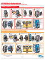
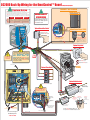
DC2000 Back-Up Wiring for the OmniControl™ Board
with Optional Equipment
SAFETY OPTIONS
System Setup
“Manual” setting: The DC2000 will respond to the input devices wired to the J 20 socket.
“Optional Edge Sensor”
This mode can also be used as an emergency override. If 115 Vac power is on, but the system has an electronic
malfunction, the gate can be operated using the DC2000 system with input devices wired to J 20 socket.
EMERGENCY
OVERRIDE
“Auto” setting: The DC2000 opens the gate automatically upon 115 Vac power failure and stays open. When
115 Vac power is restored, the gate operator will return to normal operation. (The gate can be closed by manual
command)
115 Vac Power On,
OmniControl Board™ Malfunction
115 Vac Power On,
Emergency Override
Push and Hold to
operate gate
Turn the 115 Vac power off then
push and Hold to operate gate
Push and Hold to override
the OmniControl™ Board
Gate automatically
opens
Turn the 115 Vac power off then
gate opens automatically
Push and Hold to override
the OmniControl™ Board
If 115 Vac power is on, but the system has
an electronic malfunction, the gate can be
operated using the DC2000 system with
ANY of these devices shown.
SENSOR ALARM
Manual
Mode
Auto
Mode
115 Vac Power
Failure
“Optional Manual One-Button”
DC-BACKUP
Push and “Hold” to Open
Push again and “Hold” to Close
“Optional Photocell Sensor” 12 VDC
POWER
OVERLOAD
Part # AOMRON12V
OmniControl™ Board
Sensor Connection
Part # AEXITP
Power Ground
4 5
Power +12 VDC
USE ONLY 12 VDC FAILSAFE PHOTOCELL
SENSORS FOR THIS SAFETY OPTION
Failsafe Photocell: If a photocell is not
working or loses power or photo beam is
blocked, then the photocell will stop all gate
operation.
4
6
“Optional Key Switch”
0
DC20
ness
0 Har
5
If the DC2000 is automatically opening the gate
due to a power failure, any manual command
such as “Manual One-Button”, “Three Push
Button”, “Key Switch”, “Photocell” or “Edge
Sensor” will cancel the automatic mode of the
DC2000. After such cancellation, the DC2000
will continue to operate in manual mode until
115 Vac power is restored.
DO NOT wire
115 Vac power
to the DC2000
1
56
4
3
2
4
7
OPEN
J 20
Socket
3
E
CLOS
4
Part # A1KX
Int
erl
ock
Ass
Turn and “Hold” to Open
em
bly
Wi
re
Turn again and “Hold” to Close
To Limit Switches
Interlock
Assembly
ON
OFF
“Optional Three-Button”
N.O.
4
2
4
1
4
Com
EXIT
SAFETY
CENTER
3
N.O.
N.O.
Com
“Optional Radio Receivers”
SENSOR ALARM
DC-BACKUP
Com
Push and “Hold” a Button to operate
W4
SYSTEM ON
MS LINK
TIMER
3
1
3
REVERSE
SENSOR
1
60
1
OFF
3
ON
OPEN LEFT
OPEN RIGHT
RADIO
RECEIVER
GATE
LOCKED
EXIT
LOOP
SAFETY
LOOP
CENTER
LOOP
RESET
MOTOR
STOP
STRIKE
OPEN
MADE IN USA
DO NOT remove existing
wires from the audio alarm or
secondary protection sensor.
LOSE
CLOSE
CLO
COMMAND
PROCESSED
CENTER SAFETY
FIRE
DEPT.
5 6
4 4
P/N Q410
+
G
B
A
M/S Link
Exit
Loop
Fire Dept
Key Switch
Strike Open
Push Button
Radio
Receiver
J5
Class 2
Supply
24 Volts DC
CK
BACK
-B
J5 DC-BACKUP
Black 120
White Neutral
Green Ground
CAUTION
Vac
CHASSIS
GROUND
Safety
Loop
SENSOR ALARM
OmniControl Surge SuppressorPatent Pending
11 12 13
Center
Loop
4
3 Factory installed
Interlock Assembly
Wires to J20 Socket
DC2000 Harness
For Technical Support
and Ordering Parts:
1-800-528-2806
13
12
11
11
Radio Receiver +
Radio Receiver -
2
3
4
Part # 312HM
Jumper P2:
to Constant (C)
Jumper P3:
to 12 Volt
Button Three:
Optional Accessories
White Wire
Audio Alarm
Wires
POWER
OVERLOAD
1
DC er
V
2
e 1 Receiv
t
a
r
a
Sep Radio
00
0
2
DC
Red Wire
1
11
13
11
12
Cut and
Discard Plug
Refer to Receiver
Manual for Further
Details about settings.
POWER
OVERLOAD
3
EXIT
ALARM
SENSOR
SENSORS
OPEN
G B A
2
3
4
DC
24 V nstalled
ry I
r
o
t
c
eive
Fa
c
e
io R
d
a
R
Button Two:
Back-Up Operation
(DC2000)
Button One:
Normal Gate
Operation
(OmniControl™ Board)
®
Part # 373LM
Green and Purple wires
wrap behind board to
the limit switches
Button One:
Normal Gate Operation Only
(OmniControl™ Board)
Push and “Hold” DC2000 Remote Button to Open
Push again and “Hold” DC2000 Remote Button to Close
DC2000 Back-Up Installation
for SL3000UL™ models
SL3000UL™ & SL3000ULDM™ Step-by-Step DC2000 Installation
STEP 1
STEP 2
STEP 3
STEP 4
Bolt the DC2000 plate and guard to the operator chassis. Do not tighten the
bolts. Adjustment is required in Step 3.
A Bolt the DC2000 control unit to the plate.
B Bolt the DC motor to the plate.
C Connect the DC motor wires to the DC2000 control unit wires. Red to Red and Black to Black.
A Replace the existing belt with the new belt provided. Make sure that the pulleys are aligned.
B Pull down the DC2000 Plate to tighten the belt tension. Tighten the plate bolts to secure the plate.
A
B
C
D
Remove the OmniControl™ board from the electrical box.
Plug in the DC2000 harness into the DC2000 control unit.
Feed the DC2000 harness through the bottom of the electrical box.
Feed the green and purple wires to the limit box.
OFF
Existing Belt
ON
D
A
A
A
DC2000
Control Unit
C
Plate
DC Motor
Bolts
W4
B
Plate
STEP 5
A
B
C
D
B
B
SL3000UL™
SL3000ULDM™
Use 4L 370 Belt
Use 4L 400 Belt
STEP 6
Reinstall the OmniControl™ board and make sure that the green and purple wires do not get pinched by the board.
Plug in the DC2000 harness in the DC-BackUp J5 slot on the OmniControl™ board.
Connect the red wire from the DC2000 harness into the top slot of the audio alarm plug. (DO NOT remove audio alarm wires)
Connect the white wire from the DC2000 harness into the bottom slot of the sensor plug.
A
Do not over tighten belt
B
Guard
C
STEP 7
A Connect the purple and green wires to the limit switches.
B Make sure brown wire is in the “Common” connector on the limit switch.
A Set switch for the gate
direction. (Open left or
Open right)
Top View of Limit Switch Box
operation for the DC2000
unit. (Automatic open or
Manual open)
ON
OFF
B Select your mode of
C Permanently wire optional
NC
NC
NO
3
COM
2
1
B
NO
3
COM
B
D Adjust the sensitivity for
Yellow
Orange
Purple
CK
BACK
-B
DC-BACKUP
1
Brown
Red
Green
J5
SENSOR ALARM
B
W4
2
controls according to label
on control unit. (See back
page)
D
A
C
the reverse sensor.
A
D
A
POWER
OVERLOAD
C
SL3000UL™ & SL3000ULDM™ with Interlock Assembly Step-by-Step DC2000 Installation
STEP 2
STEP 3
Bolt the DC2000 plate and guard to the operator chassis. Do
not tighten the bolts. Adjustment is required in Step 3.
A Bolt the DC2000 control unit to the plate.
B Bolt the DC motor to the plate.
C Connect the DC motor wires to the DC2000 control unit wires. Red to Red and Black to Black.
A
B
C
A
STEP 4
STEP 5
Unplug interlock wire from
OmniControl board, cut the plug
off and strip wires. Insert Red
wire in J-20 socket 3 and
Black wire into socket 4 of the
DC2000.
Remove interlock assembly from motor with 3 screws.
Replace the existing belt with the new belt provided. Make sure that the pulleys are aligned.
Pull down the DC2000 Plate to tighten the belt tension. Tighten the plate bolts to secure the plate.
Reattach interlock assembly.
A
B
C
D
Remove the OmniControl™ board from the electrical box.
Plug in the DC2000 harness into the DC2000 control unit.
Feed the DC2000 harness through the bottom of the electrical box.
Feed the green and purple wires to the limit box.
D
OFF
Existing Belt
A
Interlock
Assembly
B
B
DC2000
Control Unit
A
A
C
Plate
DC Motor
C
Bolts
ON
STEP 1
W4
C
Plate
A
C
STEP 6
A
B
C
D
1
B
Guard
7
Do not over tighten belt
B
SL3000UL™
SL3000ULDM™
Use 4L 370 Belt
Use 4L 400 Belt
Socket 3 & 4
STEP 7
Reinstall the OmniControl™ board and make sure that the green and purple wires do not get pinched by the board.
Plug in the DC2000 harness in the DC-BackUp J5 slot on the OmniControl™ board.
Connect the red wire from the DC2000 harness into the top slot of the audio alarm plug. (DO NOT remove audio alarm wires)
Connect the white wire from the DC2000 harness into the bottom slot of the sensor plug.
56
234
STEP 8
A Connect the purple and green wires to the limit switches.
B Make sure brown wire is in the “Common” connector on the limit switch.
A Set switch for the gate
direction. (Open left or
Open right)
Top View of Limit Switch Box
operation for the DC2000
unit. (Automatic open or
Manual open)
ON
OFF
B Select your mode of
C Permanently wire optional
J5
B
NC
NC
NO
3
COM
2
NO
3
COM
B
Yellow
Orange
Purple
BACK
-BACK
DC-BACKUP
1
2
Brown
Red
Green
W4
SENSOR ALARM
C
controls according to label
on control unit. (See back
page)
D
A
1
B
D Adjust the sensitivity for
the reverse sensor.
A
D
POWER
OVERLOAD
A
C
®
For Technical Support and Ordering Parts:
1-800-528-2806
01-51128B
© 2008 The Chamberlain Group, Inc.
All Rights Reserved
™
845 Larch Avenue Elmhurst, Illinois 60126
www.chamberlain.com