1
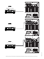
O
P E R A T I O N
. . . . . . . . .
. . . . . .
. . .
V
S
V-10S
E R I E S
AND
V-12S
....
P
O W E R E D
S
U B W O O F E R S
Cerwin-Vega’s
Limited Warranty
WELCOME
TO THE FAMILY!
First off, you have great taste in loudspeakers. At Cerwin-Vega, deep bass and
great highs are a way of life.
Nice to know there are a few people out there who share our passion for
music. And we consider you to be the newest member of the family. We hope
your speakers give you years of enjoyment. Of course, in the event of a
problem, make sure you familiarize yourself with this warranty. We like to think
that while you’re sitting in front of your speakers, we’re standing behind them.
And now a few choice words from our lawyer. (Hey, every family has one.)
WARNING: TO REDUCE THE RISK OF FIRE OR ELECTRIC
SHOCK, DO NOT EXPOSE THIS SPEAKER CABINET TO RAIN
OR MOISTURE.
WHO’S
COVERED BY THIS WARRANTY?
Cerwin-Vega’s Limited Warranty on residential speakers extends only to the original
purchaser as evidenced by the original Bill of Sale and only to the residential speakers
purchased from authorized Cerwin-Vega dealers.
Ten words of advice: retain the original bill of sale in a safe place!
WHAT’S
COVERED BY THIS WARRANTY?
Cerwin-Vega warrants that all new residential speakers shall be free from defects in
material and workmanship, under normal and proper use. Cerwin-Vega agrees to repair or
replace (at our option) all such defective parts at no charge for labor or materials.
WHAT’S NOT
COVERED BY THIS WARRANTY?
This Limited Warranty does not apply to defective equipment that: has been altered or
repaired by other than factory approved procedures; has been subjected to negligence,
misuse or accident; has been damaged by improper line voltage; had its serial number or any
part of it altered, defaced, or removed; has been used for other than home entertainment
purposes; or has been used in a way that is contrary to Cerwin-Vega’s written instructions.
Except as provided by statute, this Limited Warranty does not cover losses, consequential or
otherwise, resulting from the improper use of, or inability to operate, any Cerwin-Vega
product.
HOW
LONG DOES THE WARRANTY EXTEND?
Cerwin-Vega’s Limited Warranty extends for a period of five (5) years for all system
speaker components and two (2) years for all associated electronics components, including
amplifier and controller devices, from date of purchase as shown on the original Bill of Sale.
If a defect exists within the warranty period, the warranty will not expire until the defect
has been fixed. The warranty period will also be extended if the warranty repairs have not
been performed due to delays caused by circumstances beyond the control of the original
purchaser, or if the warranty repairs did not remedy the defect and the original purchaser
notifies Cerwin-Vega or the original dealer or an Authorized Cerwin-Vega Service Center of
the failure of the repairs within 30 days after they were completed.
SAFETY INSTRUCTIONS
READ INSTRUCTIONS - Read all safety and operating instructions before operating the product.
RETAIN INSTRUCTIONS - Retain all safety and operating instructions for future reference.
READ WARNINGS - Read all warnings on the product and in the operating instructions.
FOLLOW INSTRUCTIONS - Follow all operating and use instructions.
WATER AND MOISTURE - This apparatus shall not be exposed to dripping or splashng and
that no objects filled with liquids, such as vases, shall be placed on the apparatus. Do not
use the product near water; e.g., near a bathtub, washbowl, kitchen sink, laundry tub, in a
wet basement, or near a swimming pool, etc.
VENTILATION - Do not place the product in a location or position that interferes with its
proper ventilation. For example, do not set the product on a bed, sofa, rug, or similar
surface that may block the heat sink, or place it in a built-in situation, such as a bookcase or
cabinet that may impede the flow of air around the heat sink.
PLACEMENT - This product is designed for floor placement only. Do not place it on a cart or
table. Do not place objects on top of the product, as they will vibrate off.
HEAT - Place the product away from heat sources such as radiators, heat registers, stoves, or
other appliances (including amplifiers) that produce heat.
POWER SOURCES - Connect the product only to a power receptacle of the type described
in the operating instructions or as marked on product.
GROUNDING OR POLARIZATION - Do not defeat the product’s grounding or polarization feature.
YOU GET WARRANTY SERVICE?
In order to obtain warranty service, contact your original dealer or distributor, or an
Authorized Cerwin-Vega Service Center. If, for some reason, you have trouble locating a
service representative, contact Cerwin-Vega’s Customer Service Department for assistance:
Cerwin-Vega! Customer Service Dept. 555 East Easy Street, Simi Valley, CA 93065
POWER CORD PROTECTION - Route power-supply cords so that they are not likely to be
walked on or pinched by items placed on or against them. Pay particular attention to
cords at plugs, convenience receptacles, and the point where they exit from the product.
In some cases, the Customer Service Department can solve a service problem without
any return of equipment to Cerwin-Vega, thereby avoiding transit delays.
POWER LINES - Locate an outdoor antenna away from power lines.
HOW DO
Phone: 805-584-5300 Fax: 805-526-3653
NOW,
WHAT IF THE PRODUCT MUST BE RETURNED?
If the Customer Service Department determines that the equipment must be returned to
Cerwin-Vega for service, a Return Authorization will be issued by mail, and the defective
merchandise may be shipped directly to the above address freight prepaid, along with a
copy of both the Return Authorization and the original Bill of Sale. The product will be
replaced or repaired (at our option) and returned to the original purchaser. Only the return
postage will be paid by Cerwin-Vega. Cerwin-Vega will not be responsible for damage
occurring in shipment from the original purchaser or due to improper packing materials.
Remember to pack all equipment carefully and in the original carton if possible. Additional
charges may be added if new packing materials are required for return shipment. SAVE
YOUR ORIGINAL PACKING MATERIALS!
OTHER
REMEDIES UNDER THE LAW
The exercise of any of the provisions under the Limited Warranty does not affect the
protections or remedies of the original purchaser under other laws. If you have additional
questions about service, write or call the Customer Service Department. This Limited
Warranty applies to all residential speakers, and supersedes all previous warranty statements.
Cerwin-Vega reserves the right to make changes in product design and specifications at any
time.
EXCEPT AS PROVIDED HEREIN AND BY APPLICABLE LAW, CERWIN-VEGA MAKES NO
ADDITIONAL REPRESENTATION OR WARRANTY OF ANY NATURE WHATSOEVER,
EXPRESSED OR IMPLIED,AS TO THE EQUIPMENT, INCLUDING BUT NOT LIMITED TO,THE
MERCHANTABILITY, FITNESS FOR A PARTICULAR PURPOSE, DESIGN CONDITION OR
WORKMANSHIP OF THE EQUIPMENT, OR THE QUALITY OF THE MATERIAL INCLUDED
THEREIN,THIS LIMITED WARRANTY CONSTITUTES THE SOLE AND ENTIRE AGREEMENT
BETWEEN CERWIN-VEGA AND THE ORIGINAL PURCHASER.
CLEANING - Clean the product only with a dry cloth; do not use any liquids such as water
or solvents.
NON-USE PERIODS - Unplug the product’s power cord from the outlet when left unused
for a long period of time.
OBJECT AND LIQUID ENTRY - Use care so that objects or liquids do not enter the enclosure
through openings.
DAMAGE REQUIRING SERVICE - If the product requires service, use only qualified service
personnel when:
A.
B.
C.
D.
The power supply cord or the plug has been damaged; or
Objects have fallen, or liquid has been spilled into the product; or
The product has been exposed to rain; or
The product does not appear to operate normally, or exhibits a marked change
in performance; or
E. The product has been dropped, or the enclosure damaged; or
F.
Fuse blows repeatedly.
SERVICING - Do not attempt to service the product beyond what is described in the
operating instructions. All other servicing should be referred to qualified service
personnel. In the event your Cerwin-Vega Subwoofer fails to operate properly, please
contact the dealer where you purchased the unit. Or, for further assistance contact us at
the addresses listed below.
HEARING DAMAGE WARNING - Continuous, excessive exposure to sound pressure levels
in excess of 85 dB may cause hearing loss. Cerwin-Vega audio/video speaker systems are
capable of producing sound pressure levels greater than 85 dB.
All V Series speakers are CE compliant.
Cerwin-Vega is constantly striving to maintain the highest consumer standards. As a
result of these efforts, modifications may be made from time to time to existing products
without prior notice. Specifications and appearance may differ from those listed or shown
in this manual.
Cerwin-Vega, 555 E. Easy St., Simi Valley, CA 93065 • Phone (805) 584-9332 • Fax (805) 583-0865 • Cerwin-Vega! is a division of the Stanton Group • www.cerwin-vega.com
I n s t a l l a t i o n
TO INSTALLATION
9
Carefully unpack your subwoofer, saving the box and all of the packing material; at
some point you may need to transport, ship, or move your subwoofer. Before
continuing with the installation, please make sure the subwoofer is unplugged and
the power switch is turned “OFF.” WARNING: Severe damage may result from
improperly selected voltage. Set voltage selection switch,
10
to the proper AC voltage.
10
I NSTALLATION
Please read the following to determine which installation procedure is best for your
audio/video system. For additional hook-up connections, you may want to refer to
your A/V receiver, processor, preamplifier, or amplifier’s manual. NOTE: Be sure to read
11
POWER CORD RECEPTACLE: Connect IEC cord to this receptacle (supplied
with the V subwoofer). If the cord supplied does not fit an available AC outlet,
purchase the correct AC cord from your audio dealer or an electrical supply store.
12
REPLACEABLE FUSE: Protects system from overload, replace with fuse rating as
indicated on amplifier panel at fuse location. The fuse holder is located at the AC
receptacle. Gently pry open to access the fuse.
The following controls are located on the subwoofer’s rear panel, as shown (back cover).
Attention! The Cerwin-Vega V-10S/12S have LFE, LINE-LEVEL, and SPEAKERLEVEL input connections; choose one option only for hook-up. Do not hook up
more than one option!
1
LFE INPUT: Mono “low frequency effects”connection. Use this input if
receiver/preamp/processor has a dedicated LFE or subwoofer OUT. Refer to
the owner’s manual provided by your receiver/preamp/processor manufacturer.
(see figure 1, back cover for hook-up)
2
LINE-LEVEL INPUT: Stereo low level input to subwoofer. Connect to “LINE-OUT”,
“MAIN-OUT or PREAMP-OUT”, of your receiver/preamp/processor using a dual RCA
patchcord (not supplied). Refer to the owner’s manual provided by your receiver/
preamp/processor manufacturer. (see figure 2, back cover for hook-up)
3
SPEAKER-LEVEL INPUT: Stereo high-level inputs to subwoofer. Use these terminals
when line-level connections are not available from A/V receiver/preamp/processor.
Connect to SPEAKER outputs on receiver using high quality speaker wire (16-gauge
or heavier). (see figure 3, back cover for hook-up)
4
SPEAKER-LEVEL OUTPUT: Audio loop of stereo high-level (SPEAKER-LEVEL)
inputs 3 . Use to loop (continue) signal to speaker connections to the left
and right main speakers.
5
VOLUME CONTROL: Controls volume level of subwoofer. Use to balance the output
of the subwoofer with the main speaker output.
6
7
8
VOLTAGE SELECTION: User-switchable voltage selection for use with 115 or 230
volt AC. Attention: All subwoofer models come from the factory preset to
115 volts. To select a different voltage, use a flat head screwdriver to reposition
the switch to the desired voltage. WARNING: Severe damage may result from
improperly selected voltage. Make sure you know the voltage requirement of
the country you are in before attempting to connect this subwoofer to AC
power.
and observe the “Safety Instructions” on preceding page before starting the installation.
C ONTROL D ESCRIPTIONS
POWER: Two-position power switch. In the “ON”mode, the subwoofer’s
amplifier is automatically activated if an audio signal is present and will automatically
become inactive when there is no audio signal present after approximately 30
minutes. In the “OFF” mode, power is shut off to the amplifier.
PLACEMENT
Your V Series powered subwoofer produces low frequencies which are omnidirectional.
As a result, placement requirements for your subwoofer are flexible and subject to your
listening room’s acoustic characteristics. To determine the best position for your
subwoofer, start by positioning it along the same wall, or plane, as your main speakers.
Experiment with various locations until you find the location that sounds best to you.
Note: Typically, your powered subwoofer will sound louder when placed in close
proximity to walls or corners.
Caution! Cerwin-Vega V-10S and V-12S speakers are intended for FLOOR
PLACEMENT ONLY! Do not place heavy objects of any type, such as televisions on
top of any Cerwin-Vega speaker unless otherwise recommended by Cerwin-Vega!
V Series speakers are for residential applications only.
CROSSOVER FREQUENCY: The crossover control allows you to adjust the upper
limit of the subwoofer’s frequency response from 40 to 120 Hz. The subwoofer’s
response will begin rolling off above the set frequency. Set the CROSSOVER FREQUENCY to the lower value listed in the main speaker manual.* (Note: Crossover
control does not function when LFE input is used.)
PHASE: This switch allows you to compensate for having the subwoofer
in a different location than the main speakers. This control allows the signal to be
delayed 180 degrees so the output of the subwoofer will blend in with the
main speakers. Slide the PHASE switch to “180”. At the listening position, listen to
the midbass output. If it sounds weak, set PHASE back to “0.”
POWER LED: Power indicator lamp. Glows green in “ON”mode if audio signal is
present. Glows red in both “OFF”mode and “ON ”mode if receiving AC power,
and if audio signal is not present after approximately 30 minutes.
TROUBLESHOOTING
SYMPTOM
CAUSE
SOLUTION
Bass sounds distorted
Subwoofer amplifier has
reached maximum output
Turn down volume control
on subwoofer or lower
receiver level
Tone controls are set too high
Set bass flat; use controls
sparingly
Distortion with volume
control near minimum
Defective receiver or
preamplifier; shorted speaker
wires
Repair defective receiver,
preamplifier or replace
speaker wires
Distortion on music
peaks or sound
effects
Dynamic soundtrack (e.g.,
explosions)
Turn down volume control to
lower overall range; use a
more powerful
receiver/amplifier
Buzz, hum, or crackle
when connecting
wires
Connecting wires with power
on causes transient signal
spikes
Connect wires only when
audio system power is off
Buzz or hum when
system is on
Grounding problem or ground
loop
Check receiver or
preamplifier manual for
ground loop elimination
No sound after
Amplifier’s thermal protection
listening at high levels is on
Turn down volume control
and allow amplifier to cool;
sound should resume
automatically
* Refer to the owner’s manual provided by your main speaker manufacturer to
determine your main speaker’s low end frequency response.
SPECIFICATIONS
V-12S
V-10S
Frequency Response
(+/- 3 dB)
30 Hz - 150 Hz
32 Hz - 150 Hz
Woofer
12” EX ™ Woofer
10” EX ™ Woofer
Amplifier Power
(@0,05% THD)
150 Watts RMS
300 Watts Peak
100 Watts RMS
200 Watts Peak
Amplifier Features
Variable gain and
X-O freq.; phase select;
LFE in; line level in; speaker
level in/out; 110/220AC
Variable gain and
X-O freq.; phase select;
LFE in; line level in; speaker
level in/out; 110/220AC
Protection
AC Fuse & Thermal
AC Fuse & Thermal
Video Shielding
No
No
Weight
44 lb. / 20kg.
34 lb. / 15.6kg.
Dimensions
(H x W x D)
(inches)
(cm)
17 3⁄4 x 13 5⁄8 x 19 3⁄8
45.1 x 34.6 x 49.2
16 1⁄8 x 111⁄2 x 17 3⁄8
41x 29.2 x 44.1
ENGLISH
P RIOR
4
3
SPEAKER OUT
SPEAKER IN
2
LEFT
1
6
LINE LEVEL INPUT CROSSOVER
FREQUENCY
LEFT
LFE
-
+
-
7
PHASE
8
5
VOLUME
+
0
0
RIGHT
40Hz
RIGHT
120Hz
1800
LOW FREQUENCY EFFECTS CONNECTION
From LFE or Subwoofer Out
Low Frequency Effects Connection
9
CONFORMS TO
ANSI / UL STD.6500
CERTIFIED TO
CAN/CSA STD.E65
CAUTION
3007143
POWER
ON
12
10
RISK OF ELECTRIC
SHOCK DO NOT OPEN
11
AVIS RISQUE DE CHOC ELECTRIQUE
NE PAS OUVRIR
230
INPUT
VOLTAGE
CAUTION: TO REDUCE
THE RISK OF FIRE,
REPLACE WITH ONLY
THE SAME TYPE AND
RATING OF FUSE.
ARPL88000
OFF
ATTENTION: UTILISER
UN FUSIBLE DE
RECHANGE MEME TYPE.
4
115/230V
60/50Hz 230W
FUSE TYPE:
T1.5 AL 250V FOR 230V
T3 AL 250V FOR 115V
3
SPEAKER OUT
SPEAKER IN
2
LEFT
1
6
LINE LEVEL INPUT CROSSOVER
FREQUENCY
LFE
LEFT
-
+
-
7
PHASE
8
5
VOLUME
+
00
Figure 2
RIGHT
40Hz
RIGHT
120Hz
1800
LINE LEVEL CONNECTION
Line Level Out
9
CONFORMS TO
ANSI / UL STD.6500
CERTIFIED TO
CAN/CSA STD.E65
CAUTION
3007143
POWER
ON
12
10
RISK OF ELECTRIC
SHOCK DO NOT OPEN
11
AVIS RISQUE DE CHOC ELECTRIQUE
NE PAS OUVRIR
230
INPUT
VOLTAGE
CAUTION: TO REDUCE
THE RISK OF FIRE,
REPLACE WITH ONLY
THE SAME TYPE AND
RATING OF FUSE.
ARPL88000
OFF
ATTENTION: UTILISER
UN FUSIBLE DE
RECHANGE MEME TYPE.
4
115/230V
60/50Hz 230W
FUSE TYPE:
T1.5 AL 250V FOR 230V
T3 AL 250V FOR 115V
3
SPEAKER OUT
SPEAKER IN
2
LEFT
1
6
LINE LEVEL INPUT CROSSOVER
FREQUENCY
LFE
LEFT
+
-
-
7
PHASE
8
5
VOLUME
+
00
RIGHT
Figure 3
40Hz
RIGHT
120Hz
1800
SPEAKER-LEVEL CONNECTION
From Speaker-Level Out
9
POWER
ON
12
10
RISK OF ELECTRIC
SHOCK DO NOT OPEN
AVIS RISQUE DE CHOC ELECTRIQUE
NE PAS OUVRIR
CAUTION: TO REDUCE
THE RISK OF FIRE,
REPLACE WITH ONLY
THE SAME TYPE AND
RATING OF FUSE.
ARPL88000
ATTENTION: UTILISER
UN FUSIBLE DE
RECHANGE MEME TYPE.
11
230
INPUT
VOLTAGE
OFF
115/230V
60/50Hz 230W
FUSE TYPE:
T1.5 AL 250V FOR 230V
T3 AL 250V FOR 115V
Cerwin-Vega, 555 E. Easy St., Simi Valley, CA 93065 • Phone (805) 584-9332 • Fax (805) 583-0865 • Cerwin-Vega! is a division of the Stanton Group • www.cerwin-vega.com
TDML881111 (USA 11/03)
CAUTION
CONFORMS TO
ANSI / UL STD.6500
CERTIFIED TO
CAN/CSA STD.E65
3007143


![PS manual[P].qXp2](http://vs1.manualzilla.com/store/data/005858764_1-0e0b40902f5a565498b3e3a041c7e706-150x150.png)