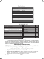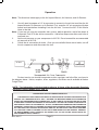
1
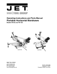
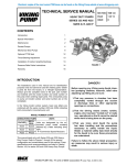
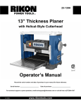
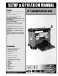
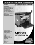
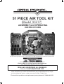
R
51 PIECE AIR TOOL KIT
Model 93217
ASSEMBLY and OPERATING
INSTRUCTIONS
Due to continuing improvements , actual product may differ s lightly from the product des cribed herein.
3491 Mis s ion Oaks B lvd., C amarillo, C A 93011
Visit our Web site at http://www.harborfreight.com
TO PREVENT SERIOUS INJURY,
READ AND UNDERSTAND ALL WARNINGS
AND INS T R UCTIONS BEFORE USE.
C opyright© 2005 by Harbor FreightTools ® . All rights reserved. No portion
of this manual or any artwork contained herein may be reproduced in any s hape
or form without the expres s written cons ent of Harbor Freight Tools.
For technical questions and replacement parts, please call 1-800-444-3353
Specifications
Air Inlet
Operating P ressure
Air Ratchet Dimensions
Drive S ize
Maximum T orque Output
Operating R P M’s
Air C onsumption
Air R atchet Weight
Impact Wrench Dimensions
Driver S ize
Air C onsumption
Operating R P M’s
Maximum T orque Output
Impact Wrench Weight
Air Hammer Dimens ions
C huck Diameter
B lows P er Minute
Air C onsumption
Air Hammer Weight
1/4”-18 NP T (All tools )
90 P S I (All tools)
10-3/8”L x 2-1/8”H x 1-5/8” Dia.
3/8” S q.
50 F t. Lbs .
150 R P M
4 CFM
2.6 Lbs .
7-1/8”L x 8”H x 2-3/4”W
1/2” S q.
4 CFM
7,000 R P M
230 F t. Lbs .
5.0 Lbs.
6-3/4” L x 2” W x 6” H
0.403”
4,500 B P M
3.4 C F M
2.4 Lbs .
ACCESSORY LIST
Description
B lowmold C arrying C ase
1/2” Drive, 3” E xtension B ar
Drive Adapter 3/8” to 1/2”
Impact S ocket 5/8”, 3/4”, 11/16”, 1/2”, 9/16”
11mm, 12mm, 13mm, 14mm, 17mm
1/4” Hex Driver B its
C his el
C hisel S pring
Air R egulator
S wivel Hose C onnector
B lowgun
R ubber Nozzle
S afety Nozzle
High P ressure Nozzle
T apered Nozzle
Qty.
1
1
1
10
6
3
1
1
1
1
1
1
1
1
Description
Dual F oot T ire G auge
B all F oot T ire C huck
F emale Hose C onnector
F emale Nipple
Male Nipple
Male Hose C onnector
F emale Quick C oupler
S ports Needle
S ports Adapter
Air T ool Oiler
B ottle of Air T ool Oil
R oll of T eflon T ape
Hex B it Adapter
Allen Wrench
Qty.
1
1
1
1
5
1
1
1
1
1
1
1
1
1
Save This Manual
You will need the manual for the safety warnings and precautions, assembly instructions,
operating and maintenance procedures, parts lis t and diagram. Keep your invoice with this
manual. Write the invoice number on the ins ide of the front cover. Keep the manual and
invoice in a s afe and dry place for future reference.
Safety Warnings and Precautions
WARNING: When using tools, basic safety precautions should always be followed to
reduce the risk of personal injury and damage to equipment.
Read all instructions before using this product!
1.
2.
Keep work area clean. C luttered areas invite injuries .
Observe work area conditions. Do not us e machines or power tools in damp or wet
locations . Don’t expos e to rain. K eep work area well lit. Do not us e electrically
powered tools in the pres ence of flammable gas es or liquids.
S K U 93217
P age 2
3.
4.
Keep children away. Children must never be allowed in the work area. Do not let
them handle machines, tools, extension cords, or air hoses.
Store idle equipment. When not in use, tools must be stored in a dry location to
inhibit rust. Always lock up tools and keep out of reach of children.
5.
Use the right tool for the job. Do not attempt to force a small tool or attachment to do
the work of a larger industrial tool. There are certain applications for which these tools
were designed. They will do the job better and more safely at the rate for which they
were intended. Do not modify these tools and do not use these tools for a purpose for
which they were not intended.
6.
Dress properly. Do not wear loose clothing or jewelry as they can be caught in
moving parts. Protective, electrically non-conductive clothes and non-skid footwear
are recommended when working. Wear restrictive hair covering to contain long hair.
7.
Use eye and ear protection. Always wear ANSI approved impact safety goggles.
Wear a full face shield if you are producing metal filings, or flying chips of wood,
concrete, metal or any other material. Wear an ANSI approved dust mask or respirator
when working around metal, wood, and chemical dusts and mists.
8.
Do not overreach. Keep proper footing and balance at all times. Do not reach over
or across running machines or air hoses.
9.
Maintain tools with care. Keep tools clean for better and safer performance. Follow
instructions for lubricating and changing accessories. Inspect tool cords and air hoses
periodically and, if damaged, have them repaired by an authorized technician. The
handles must be kept clean, dry, and free from oil and grease at all times.
10. Disconnect air supply. Disconnect air hose when not in use.
11. Remove adjusting keys and wrenches. Check that keys and adjusting wrenches
are removed from the tool or machine work surface before connecting the tool.
12. Avoid unintentional starting. Be sure the trigger is released when not in use and
before connecting to the air source. Do not carry any tool with your finger on the
trigger, whether it is connected or not.
13. Stay alert. Watch what you are doing, use common sense. Do not operate any tool
when you are tired.
14. Check for damaged parts. Before using any tool, any part that appears damaged
should be carefully checked to determine that it will operate properly and perform its
intended function. Check for alignment and binding of moving parts; any broken parts
or mounting fixtures; and any other condition that may affect proper operation. Any
part that is damaged should be properly repaired or replaced by a qualified
technician. Do not use the tool if the trigger does not operate properly.
15. Guard against electric shock. Prevent body contact with grounded surfaces such as
pipes, radiators, ranges, and refrigerator enclosures.
16. Replacement parts and accessories. When servicing, use only identical
replacement parts. Use of any other parts will void the warranty. Only use accessories
intended for use with these tools. Approved accessories are available from Harbor
Freight Tools.
SKU 93217
Page 3
17. Industrial applications must follow OSHA guidelines.
18. Do not operate tool if under the influence of alcohol or drugs. Read warning labels
if taking prescription medicine to determine if your judgement or reflexes are impaired
while taking drugs. If there is any doubt, do not operate the tool.
19. Use proper size and type extension cord. If an extension cord is required for an air
compressor, it must be of the proper size and type to supply the correct current to the
compressor without heating up. Otherwise, the extension cord could melt and catch
fire, or cause electrical damage to the compressor. Check your air compressor’s
manual for the appropriate size cord.
20. Maintenance. For your safety, maintenance should be performed regularly by a
qualified technician.
21. Compressed air only. Never use combustible gas as a power source.
22. Use both hands. The torque generated from these tools can cause the tools to break
free of your grasp, causing serious injury and damage. Always operate the tools with
both hands.
Note: Performance of the compressor (if powered by line voltage) may vary depending
on variations in local line voltage. Extension cord usage may also affect tool performance.
Warning:The warnings, cautions, and instructions discussed in this instruction manual
cannot cover all possible conditions and situations that may occur. It must be understood
by the operator that common sense and caution are factors which cannot be built into
this product, but must be supplied by the operator.
WARNING: Some dust created by power sanding, sawing, grinding, drilling, and
other construction activities, contain chemicals known [to the State of California]
to cause cancer, birth defects or other reproductive harm. Some examples of
these chemicals are:
Lead from lead-based paints
Crystalline silica from bricks and cement or other masonry products
Arsenic and chromium from chemically treated lumber
Your risk from these exposures varies, depending on how often you do this type
of work. To reduce your exposure to these chemicals: work in a well ventilated
area, and work with approved safety equipment, such as those dust masks that
are specially designed to filter out microscopic particles.
(California Health & Safety Code 25249.5, et seq. )
Unpacking
When unpacking, check to make sure all of the parts listed on pages 10-13 are included.
If any parts are missing or broken, please call Harbor Freight Tools at the number on the cover
of this manual as soon as possible.
SKU 93217
Page 4
Operation
Note: The directions below apply to the Air Impact Wrench, Air Hammer, and Air Ratchet.
1.
You will need to prepare a 1/4” air connector to connect to the air inlet on either the Air
Impact Wrench, Air Hammer, or Air Ratchet. First, wrap the 1/4” air connector with pipe
thread seal tape before threading it into the Air Inlet. Connect the 3/8” ID Air Source
Hose to the tool.
Note: If you are not using an automatic oiler system, before operation, add a few drops of
Pneumatic Tool Oil to the airline connection. Add a few drops more after each hour of
continual use.
2.
Set the air pressure on your compressor to 90 PSI. Do not exceed the recommended
air pressure of 90 PSI.
3.
Check the air connection for leaks. Once you are satisfied there are no leaks, turn off
the air compressor and disconnect the tool.
Air Tool
1/4”-NPT
For best service you should incorporate an oiler, regulator, and inline filter, as shown in
the diagram above. Hoses, couplers, oilers, regulators, and filters are all available at Harbor
Freight Tools.
NOTE: The information in the box below refers to all three of the Assembly Drawings
and Parts Lists on pages 10, 11, and 12.
PLEASE READ THE FOLLOWING CAREFULLY
THE MANUFACTURER AND/OR DISTRIBUTOR HAS PROVIDED THE PARTS DIAGRAM IN THIS
MANUAL AS A REFERENCE TOOL ONLY. NEITHER THE MANUFACTURER NOR DISTRIBUTOR
MAKES ANY REPRESENTATION OR WARRANTY OF ANY KIND TO THE BUYER THAT HE OR SHE
IS QUALIFIED TO MAKE ANY REPAIRS TO THE PRODUCT OR THAT HE OR SHE IS QUALIFIED TO
REPLACE ANY PARTS OF THE PRODUCT. IN FACT,THE MANUFACTURER AND/OR DISTRIBUTOR
EXPRESSLY STATESTHAT ALL REPAIRS AND PARTS REPLACEMENTS SHOULD BE UNDERTAKEN
BY CERTIFIED AND LICENSED TECHNICIANS AND NOT BY THE BUYER. THE BUYER ASSUMES
ALL RISK AND LIABILITY ARISING OUT OF HIS OR HER REPAIRS TO THE ORIGINAL PRODUCT
OR REPLACEMENT PARTS THERETO, OR ARISING OUT OF HIS OR HER INSTALLATION OF
REPLACEMENT PARTS THERETO.
SKU 93217
Page 5
Air Ratchet Operation
FIGURE 1
Reverse Switch (13)
Air Inlet (1)
Trigger Pivot Area
Throttle Lever (5)
Anvil (15)
Warning! Do not use a “cheater” bar or other extension to increase torque for this tool.
Do not exceed the maximum torque rating on this tool.
Warning! Disconnect the Ratchet from the air source when attaching and removing
sockets. There is no safety lock mechanism on this tool; always disconnect from the
air source when not in use.
Refer to the photograph above.
1.
Attach a 3/8” drive socket to the Ratchet Anvil (15).
2.
By following the directions on page 5, attach the Ratchet to the air source hose.
3.
Gently press the Throttle Lever (5) to activate the Ratchet. Do not force the unit;
allow it to do the work for you. To change direction (loosen vs. tighten), stop the tool
and move it away from the workpiece, then turn the Reverse Switch (13).
4.
To adjust the torque, re-adjust the air pressure by changing the setting on the compressor.
Do not exceed the maximum air pressure of 90 PSI for this tool at any time.
5.
When you are finished working, turn off the compressor and disconnect the air source
hose.
Warning! There may still be air in the Ratchet. Squeeze the Throttle Lever (5) and activate the
Ratchet to expel any air still inside the tool.
6.
Remove the socket.
Maintenance
Warning! Always disconnect the Ratchet from the air source hose before attempting any
maintenance.
1.
Wipe the unit down with a lint free cloth.
2.
Periodically apply a high grade, light machine oil to the Trigger Pivot area (see above).
3.
Make sure the Ratchet Anvil (15), the Air Inlet (01), and the Reverse Switch (13) are
clear of grease, dirt, or debris.
SKU 93217
Page 6
Air Impact Wrench Operation
FIGURE 2
Oil Screw (44)
Anvil (18)
Forward/Reverse Lever
Air Inlet (10)
Air Regulator (12)
Trigger (4)
Warning!! This Impact Wrench supplies powerful torque and is designed to be operated with
two hands. Failure to operate the Impact Wrench with two hands may result in serious injury.
Note: Turn off your air compressor and disconnect the air hose when you are changing sockets.
After you attach the socket, attach the air hose and turn the air compressor on.
1.
Select the appropriate size 1/2” impact drive socket for your needs.
2.
Push and snap the socket onto the Anvil (18).
Tightening
Note: Slide the Forward/Reverse Lever (3) toward the front of the Wrench.
3.
If available, check the recommended torque specification for the nut. To accurately
tighten hardware, use a torque wrench (not included) to tighten the nut to the proper
setting, instead of the impact wrench.
4.
Tighten the nut as tight as you can by hand.
5.
Place the socket over the nut you wish to tighten.
6.
Grip the Impact Wrench firmly with two hands and gently squeeze the Trigger (4).
Note: With the Trigger (4) released, fine tune the air flow with the Air Regulator (12) knob.
Note: If the Impact Wrench cannot tighten the nut to your satisfaction, do not raise the air
pressure on the compressor over 90 PSI. Pressures above 90 PSI will strip the workpiece
and damage the tool. Use other appropriate methods and tools to tighten the nut.
7.
When the nut is tightened, release the Trigger (4). Turn off the air compressor and
disconnect the hose.
Loosening
Note: Slide the Forward/Reverse Lever (3) toward the rear of the Wrench.
8.
Place the socket over the nut you wish to loosen.
9.
Grip the Impact Wrench firmly with two hands and gently squeeze the Trigger (4).
Note: If the Impact Wrench cannot loosen the nut, do not raise the air pressure on the
compressor over 90 PSI. Do not attempt to loosen the nut with the Impact Wrench. Use
other appropriate methods and tools to loosen the nut.
10.
When the nut is loosened, release the Trigger (4). Turn off the air compressor and
disconnect the hose.
11.
If needed, remove the nut from the socket.
Page 7
SKU 93217
Air Impact Wrench Maintenance
1.
2.
3.
4.
5.
Make sure your Impact Wrench is disconnected from the air hose before attempting
any maintenance.
If you are not using an automatic oiler system, put a few drops of pneumatic tool oil
through the air line before and after each use. During use, add a few drops every hour.
Apply a few drops of oil to the oil entry port before each use. Remove the Screw, add
the oil, then replace the Screw. See FIGURE 2 on page 7.
Wipe the Impact Wrench down with a lint free cloth after each use.
Make sure the Anvil (18) is clear of dirt and debris. If possible, spray it with compressed
air before each use.
Air Hammer Operation
FIGURE 3
Cylinder (16)
Retainer Spring (17)
Trigger (6)
Regulator (5)
Chisel
Air Inlet (10)
Additional Air Hammer Specific Safety Warnings.
1.
Repetitive motions or exposure to vibration may be harmful to your hands and arms.
2.
When wearing gloves to operate the Air Hammer, make sure that the gloves do not
interfere with operating the Trigger (6). Test your gloves with the Trigger (6) before attaching the unit to an air source.
3.
Never start the tool unless you have a firm grip with both hands and you are positioned
at your workpiece or area.
4.
Before using the Air Hammer, know what is directly underneath the work area or
workpiece. The Air Hammer can quickly penetrate material. If working directly on the
ground, make sure you are not directly above shallow cables, lines, or pipes.
5.
Keep your limbs and body clear of the Air Hammer. If a chisel or bit breaks off, the tool
tends to surge forward suddenly. Make sure the immediate area is clear of other people
or animals. Spectators must stay at a safe distance.
6.
Never point the tool or the air hose (not included) at anyone.
7.
Keep your finger away from the Trigger (6) until you are ready to work.
Warning!! Any spectators in the area will need eye and ear protection.
Beware of flying chips of wood, concrete, metal, or any other material being hammered.
SKU 93217
Page 8
Air Hammer Operation (continued)
Examine your chisels/bits before using them. If a chisel is dull or cracked do not use it.
Replace worn or broken chisels with approved replacement chisels/bits from
Harbor Freight Tools.
Warning!! Always disconnect the tool from the air source
before examining or changing bits.
1.
Select the appropriate chisel/bit. Unscrew the Retainer Spring (17) and insert the shank
of the chisel/bit. Screw the Retainer Spring (17) back onto the Cylinder (16).
Holding the Air Chisel firmly, pull the chisel/bit hard to make sure it locked into place.
Note: Before connecting the air supply, make sure you are wearing safety goggles and a full
face mask, ear protection, and steel toe shoes.
Warning!! Any spectators in the immediate area will need eye and ear protection.
Beware of flying chips of wood, concrete, metal, or any other material being chiseled.
2.
Connect the air hose to the Air Inlet (11) and turn on the compressor (not included).
3.
Grip the Air Hammer with both hands firmly and put the chisel/bit tip up against the
workpiece you wish to chip.
4.
Gently squeeze the Trigger (6) and move slowly along the workpiece. Do not push
down on the Air Hammer; let it do the work. If it does not do the intended job to satisfaction, examine your bit to see if it is worn or dull.
Warning!! Always disconnect from the air source before examining or changing bits.
5.
When you are finished, turn off the air supply and then hold the Air Hammer in a safe
direction and Squeeze the trigger to bleed off the remaining air. Then, disconnect the
air hose.
Maintenance
Warning!! Always disconnect from the air source before attempting maintenance.
1.
After each use, wipe the Air Hammer down with a lint free cloth.
2.
Make sure there are no concrete chips, dirt, or debris in the Retainer Spring (17).
3.
Before storage, add a small quantity of high quality pneumatic oil in the Air Inlet (11)
and operate the tool for a couple of seconds to lubricate and protect the internal
mechanism.
4.
Examine your chisels/bits before using them. If a chisel is dull or cracked do not use it.
Replace worn or broken chisels with approved replacement chisels from Harbor Freight
Tools.
SKU 93217
Page 9
Air Ratchet Assembly Drawing
Part
No.
Description
Qty
Part
No.
Description
Qty
1
Air Inlet
1
27
Needle Bearing HK1212
1
2
Throttle Spring
1
28
Front End Plate
1
3
Valve Stem
1
29
Ball Bearing (608zz)
1
5
Throttle Lever
1
30
Crank Shaft
1
6
Spring Pin (2.5x22)
1
31
Spring Cap
1
7
O Ring (P8)
1
32
Internal Stop Ring (R29)
1
8
Friction Spring
2
34
Trust Washer
1
9
Pawl
1
35
Throttle Valve
1
10
Steel Ball (4)
2
36
Needle Roller4.5*12.8
1
11
Throttle Handle
1
37
Ratchet Housing
1
12
Throttle Valve Plug
1
38
Clamp Nut
1
13
Reverse Switch
1
39
Ratchet Yoke
1
15
Ratchet Anvil
1
40
Spring Pin (2.5x6)
1
16
Drive Bushing
1
41
Idler Spindle
1
17
Ratchet Spring
1
42
Idler Gear
3
18
Ball Bearing (626zz)
1
43
Needle Roller 4*14.8
3
20
Steel Ball (5)
1
45
Internal Gear
1
21
Rear End Plate
1
46
Exhaust Cover
1
22
Spring Pin (2x6)
1
49
Bushing
1
23
Cylinder
1
50
Bearing Cap
1
24
Rotor
1
53
O-Ring (3x2)
1
25
Rotor Blade
4
56
Washer
1
SKU 93217
Page 10
Air Impact Wrench Assembly Drawing
Part
No.
1
2
3
4
5
6
7
8
9
10
12
13
14
15
16
17
18
19
20
21
22
SKU 93217
Description
Housing
Valve Sleeve
Forward/Reverse Lever
Trigger
Pin 3x14
Bushing
Valve Stem
Steel Ball Ø 10
Spring
Air Inlet
Air Regulator
O Ring (P6)
Spring
O Ring (P7)
Screw M5x0.8x8L
Anvil Bushing
Anvil
Hammer Cage
Hammer Pin
Hammer Dog
Drive Cam
Qty
1
1
1
1
2
1
1
1
1
1
1
1
1
1
1
1
1
1
1
1
1
Part
No.
24
25
26
27
28
29
30
31
32
33
34
35
36
37
38
39
40
41
42
43
44
Page 11
Description
Cylinder
Rotor
Rotor Blade
Front End Plate
Ball Bearing 6001ZZ
Rear End Plate
Pin 3*10
Spring
Pin
Rear Gasket
Rear Cover
Washer (Ø 5)
Screw M5*15
Protecting Rubber
Exhaust Deflector
Screw 3*8
Screw M5*8
Anvil Collar & Seal
O Ring
Rubber
Oil Screw
Qty
1
1
6
1
2
1
1
1
1
1
1
4
4
1
1
2
1
1
1
1
1
Air Hammer Assembly Drawing
Part
No.
1
2
3
5
6
7
8
9
SKU 93217
Description
Housing
Spring Pin3*14
O-Ring (P9)
Air Regulator
Trigger
O Ring (P3)
Valve Stem
Valve
Qty
1
2
2
1
1
1
1
1
Part
No.
10
11
12
13
14
15
16
17
Page 12
Description
Spring
Air Inlet
Upper Valve
Valve Disc
Lower Valve
Piston
Cylinder
Retainer Spring
Qty
1
1
1
1
1
1
1
1