1
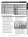
Table of Contents
Safetye��������������������������������������������������������� 3
Maintenancei���������������������������������������������� 16
Specifications.............................................. 7
Parts Lists and Diagrams........................... 18
Setup........................................................... 8
Warranty..................................................... 20
Safety
Operationa��������������������������������������������������� 14
WARNING SYMBOLS AND DEFINITIONS
This is the safety alert symbol. It is used to alert you to potential personal injury hazards.
Obey all safety messages that follow this symbol to avoid possible injury or death.
Setup
Indicates a hazardous situation which, if not avoided,
will result in death or serious injury.
Indicates a hazardous situation which, if not avoided,
could result in death or serious injury.
Indicates a hazardous situation which, if not avoided,
could result in minor or moderate injury.
Addresses practices not related to personal injury.
Operation
Maintenance
Page 2
For technical questions, please call 1-800-444-3353.
Item 60738
IMPORTANT SAFETY INSTRUCTIONS
Safety
INSTRUCTIONS PERTAINING TO A RISK OF FIRE,
ELECTRIC SHOCK, OR INJURY TO PERSONS
WARNING – When using tools, basic precautions should always be followed, including the following:
General
To reduce the risks of electric shock,
fire, and injury to persons, read all the
instructions before using the tool.
1. Keep the work area clean and well lighted.
Cluttered benches and dark areas increase the
risks of electric shock, fire, and injury to persons.
3. Keep bystanders, children, and visitors away
while operating the tool. Distractions are able
to result in the loss of control of the tool.
2. Do not operate the tool in explosive atmospheres,
such as in the presence of flammable liquids,
gases, or dust. The tool is able to create sparks
resulting in the ignition of the dust or fumes.
Setup
Work Area
Personal Safety
3. Avoid unintentional starting. Be sure the switch
is off before connecting to the air supply.
Do not carry the tool with your finger on the switch or
connect the tool to the air supply with the switch on.
5.
Use safety equipment.
A dust mask, non-skid safety shoes and
a hard hat must be used for the
applicable conditions.
6.
Always wear eye protection.
Wear ANSI-approved safety goggles.
7.
Always wear hearing protection
when using the tool.
Prolonged exposure to high intensity
noise is able to cause hearing loss.
8. Wear heavy-duty work gloves during use.
Item 60738
For technical questions, please call 1-800-444-3353.
Page 3
Operation
2. Dress properly. Do not wear loose
clothing or jewelry. Contain long hair.
Keep hair, clothing, and gloves away from
moving parts. Loose clothes, jewelry, or long
hair increases the risk of injury to persons as
a result of being caught in moving parts.
4. Do not overreach.
Keep proper footing and balance at all times.
Proper footing and balance enables better
control of the tool in unexpected situations.
Maintenance
1. Stay alert. Watch what you are doing and
use common sense when operating the tool.
Do not use the tool while tired or under the
influence of drugs, alcohol, or medication.
A moment of inattention while operating the
tool increases the risk of injury to persons.
Tool Use and Care
1. Do not force the tool. Use the correct tool for the
application. The correct tool will do the job better
and safer at the rate for which the tool is designed.
Safety
2. Do not use the tool if the switch does not turn the
tool on or off. Any tool that cannot be controlled
with the switch is dangerous and must be repaired.
3. Disconnect the tool from the air source
before making any adjustments, changing
accessories, or storing the tool. Such preventive
safety measures reduce the risk of starting the
tool unintentionally. Turn off and detach the air
supply, safely discharge any residual air pressure,
and release the throttle and/or turn the switch to
its off position before leaving the work area.
5. Maintain the tool with care. Keep a cutting
tool sharp and clean. A properly maintained
tool, with sharp cutting edges reduces the
risk of binding and is easier to control.
6. Check for misalignment or binding of moving
parts, breakage of parts, and any other condition
that affects the tool's operation. If damaged,
have the tool serviced before using. Many accidents
are caused by poorly maintained tools.
There is a risk of bursting if the tool is damaged.
7. Use only accessories that are identified by the
manufacturer for the specific tool model. Use of
an accessory not intended for use with the specific
tool model, increases the risk of injury to persons.
Setup
4. Store the tool when it is idle out of reach
of children and other untrained persons.
A tool is dangerous in the hands of untrained users.
Service
1. Tool service must be performed only
by qualified repair personnel.
2. When servicing a tool, use only identical
replacement parts. Use only authorized parts.
Air Source
1.
Operation
Never connect to an air source that is
capable of exceeding 200 psi.
Over pressurizing the tool may cause
bursting, abnormal operation, breakage
of the tool or serious injury to persons.
Use only clean, dry, regulated compressed air at the
rated pressure or within the rated pressure range as
marked on the tool. Always verify prior to using the
tool that the air source has been adjusted to the rated
air pressure or within the rated air-pressure range.
2. Never use oxygen, carbon dioxide, combustible
gases or any bottled gas as an air source
for the tool. Such gases are capable of
explosion and serious injury to persons.
SAVE THESE INSTRUCTIONS.
Maintenance
Page 4
For technical questions, please call 1-800-444-3353.
Item 60738
Symbols and Specific Safety Instructions
Symbol Definitions
.../min
Symbol
Property or statement
No-load speed
NPT
National pipe thread, tapered
Revolutions or reciprocation per minute
NPS
National pipe thread, straight
PSI
Pounds per square inch of pressure
ft-lb
Foot-pounds of torque
BPM
Blows per minute
CFM
Cubic Feet per Minute flow
SCFM
Cubic Feet per Minute flow
at standard conditions
Safety
no
Property or statement
WARNING marking
concerning Risk of Eye Injury.
Wear ANSI‑approved eye protection.
WARNING marking concerning Risk of
Hearing Loss. Wear hearing protection.
WARNING marking concerning
Risk of Respiratory Injury. Wear
NIOSH‑approved dust mask/respirator.
WARNING marking concerning
Risk of Explosion.
Setup
Symbol
Specific Safety Instructions
1. The warnings and precautions discussed in this
manual cannot cover all possible conditions and
situations that may occur. It must be understood
by the operator that common sense and caution
are factors which cannot be built into this
product, but must be supplied by the operator.
7. Attach all accessories properly to the tool before
connecting the air supply. A loose accessory
may detach or break during operation.
2. WARNING: This product, when used for abrasive
blasting and similar applications, produces chemicals
known to the State of California to cause cancer
and birth defects (or other reproductive harm).
(California Health & Safety Code § 25249.5, et seq.)
9. Install an in-line shutoff valve to allow
immediate control over the air supply in an
emergency, even if a hose is ruptured.
4. WARNING: Handling the cord on this product will
expose you to lead, a chemical known to the State
of California to cause cancer, and birth defects or
other reproductive harm. Wash hands after handling.
(California Health & Safety Code § 25249.5, et seq.)
5. Before each use, check the seal on all
doors of the Blast Cabinet. Only operate the
Blast Cabinet with all doors securely closed.
6. People with pacemakers should consult their
physician(s) before use. Electromagnetic fields in
close proximity to heart pacemaker could cause
pacemaker interference or pacemaker failure.
Item 60738
NAMEPLATE
AMPERES
(at full load)
EXTENSION CORD
LENGTH
25′
50′ 100′ 150′
0–6
18
16
16
14
6.1 – 10
18
16
14
12
10.1 – 12
16
16
14
12
12.1 – 16
14
12
Do not use.
10. USE PROPER EXTENSION CORD. Make sure your
extension cord is in good condition. When using
an extension cord, be sure to use one heavy
enough to carry the current your product will
draw. An undersized cord will cause a drop in line
voltage resulting in loss of power and overheating.
Table A shows the correct size to use depending
on cord length and nameplate ampere rating.
If in doubt, use the next heavier gauge.
The smaller the gauge number, the heavier the cord.
For technical questions, please call 1-800-444-3353.
Operation
Table A: RECOMMENDED MINIMUM WIRE GAUGE
FOR EXTENSION CORDS
(120 VOLT)
Page 5
Maintenance
3. WARNING: The brass components of
this product contain lead, a chemical
known to the State of California to cause
birth defects (or other reproductive harm).
(California Health & Safety Code § 25249.5, et seq.)
8. Obey the manual for the air compressor
used to power this tool.
Silicosis and Aluminum Oxide Warnings
Safety
WARNING! Abrasive blasting with sand containing crystalline silica can cause serious or fatal respiratory disease.
Exposure to crystalline silica may cause silicosis (a serious lung disease), cancer and death. Exposure to aluminum
oxide (a dust generated from material removing processes) can result in eye, skin and breathing irritation. Always
use a NIOSH (National Institute for Occupational Safety and Health) approved respirator and safety goggles. Avoid
skin exposure. Proper ventilation in the work area is required. Read and understand the 10 recommended measures
below to reduce crystalline silica exposures in the workplace and prevent silicosis and silicosis related deaths.
NIOSH recommends the following measures to reduce crystalline silica exposures
in the workplace and prevent silicosis and silicosis-related deaths:
1. Prohibit silica sand (or other substances
containing more than 1% crystalline silica)
as an abrasive blasting material and
substitute less hazardous materials.
2. Conduct air monitoring to measure worker exposures.
3. Use containment methods such as blast-cleaning
machines and cabinets to control the hazard
and protect adjacent workers from exposure.
Setup
4. Practice good personal hygiene to avoid
unnecessary exposure to silica dust.
5. Wear washable or disposable protective clothes
at the work site. Shower and change into clean
clothes before leaving the work site to prevent
contamination of cars, homes and other work areas.
6. Use respiratory protection when source controls
cannot keep silica exposures below the NIOSH REL.
7. Provide periodic medical examinations for all
workers who may be exposed to crystalline silica.
8. Post signs to warn workers about the hazard and to
inform them about required protective equipment.
9. Provide workers with training that includes
information about health effects, work practices
and protective equipment for crystalline silica.
10. Report all cases of silicosis to State health
departments and to OSHA or the Mine Safety
and Health Administration (MSHA).
Vibration Precautions
This tool vibrates during use. Repeated or long-term exposure to vibration may cause temporary or permanent
physical injury, particularly to the hands, arms and shoulders. To reduce the risk of vibration-related injury:
Operation
1. Anyone using vibrating tools regularly or for an
extended period should first be examined by a
doctor and then have regular medical check-ups to
ensure medical problems are not being caused or
worsened from use. Pregnant women or people who
have impaired blood circulation to the hand, past
hand injuries, nervous system disorders, diabetes,
or Raynaud's Disease should not use this tool.
If you feel any symptoms related to vibration (such
as tingling, numbness, and white or blue fingers),
seek medical advice as soon as possible.
2. Do not smoke during use. Nicotine reduces
the blood supply to the hands and fingers,
increasing the risk of vibration-related injury.
3. Wear suitable gloves to reduce the
vibration effects on the user.
4. Use tools with the lowest vibration
when there is a choice.
5. Include vibration-free periods each day of work.
6. Grip tool as lightly as possible (while still keeping
safe control of it). Let the tool do the work.
7. To reduce vibration, maintain
tool as explained in this manual.
If abnormal vibration occurs, stop immediately.
Maintenance
SAVE THESE INSTRUCTIONS.
Page 6
For technical questions, please call 1-800-444-3353.
Item 60738
TO PREVENT ELECTRIC SHOCK AND DEATH FROM INCORRECT GROUNDING WIRE CONNECTION
READ AND FOLLOW THESE INSTRUCTIONS:
110-120 V~ Grounded Tools: Tools with Three Prong Plugs
3. Improper connection of the equipment-grounding
conductor can result in a risk of electric shock.
The conductor with insulation having an outer
surface that is green with or without yellow
stripes is the equipment-grounding conductor.
If repair or replacement of the electric cord or
plug is necessary, do not connect the equipmentgrounding conductor to a live terminal.
4. Check with a qualified electrician or service
personnel if the grounding instructions are
not completely understood, or if in doubt as
to whether the tool is properly grounded.
5. Use only 3-wire extension cords that
have 3-prong grounding plugs and 3-pole
receptacles that accept the tool’s plug.
Grounding
Pin
Setup
2. Do not modify the plug provided – if it will
not fit the outlet, have the proper outlet
installed by a qualified electrician.
6. Repair or replace damaged or worn cord immediately.
125 V~ 3-Prong Plug and Outlet
(for up to 125 V~ and up to 15 A)
7. This tool is intended for use on a circuit
that has an outlet that looks like the one
illustrated above in IMPORTANT SAFETY
INSTRUCTIONS. The tool has a grounding
plug that looks like the plug illustrated above
in IMPORTANT SAFETY INSTRUCTIONS.
8. The outlet must be properly installed and grounded
in accordance with all codes and ordinances.
9. Do not use an adapter to connect
Operation
1. In the event of a malfunction or breakdown,
grounding provides a path of least resistance for
electric current to reduce the risk of electric shock.
This tool is equipped with an electric cord having an
equipment-grounding conductor and a grounding
plug. The plug must be plugged into a matching
outlet that is properly installed and grounded in
accordance with all local codes and ordinances.
Safety
Grounding Instructions
this tool to a different outlet.
Functional Description
Specifications
120V~ / 60Hz / 40W (Light)
120V~ / 60Hz / 12A (Motor)
Fluorescent Bulb 18W, 23″ L x 1″ Dia. (Qty. 2)
Working Pressure 50 ~ 125 PSI
Air Consumption 13 ~ 15 CFM @ 80 PSI
Air Inlet Size
3/8″-18 NPT
Abrasive Capacity Approximately 15 lb.
Inner Cabinet
47-3/4″ W x 24″ D x 22‑1/2″ H (Rear), 14″ H (Front)
Front Window
22-1/2″ W x 10-1/2″ H
Accessories
4mm, 5mm, 6mm & 7mm Ceramic Nozzles
Item 60738
For technical questions, please call 1-800-444-3353.
Maintenance
Electrical Rating
Page 7
Initial Tool Set Up/Assembly
Read the ENTIRE IMPORTANT SAFETY INFORMATION section at the beginning of this
manual including all text under subheadings therein before set up or use of this product.
Safety
Note: For additional information regarding the parts listed in the following pages,
refer to the Assembly Diagram near the end of this manual.
Note: This air tool may be shipped with a protective plug covering the air inlet. Remove this plug before set up.
Air Supply
TO PREVENT SERIOUS INJURY FROM EXPLOSION:
Use only clean, dry, regulated, compressed air to power this tool.
Do not use oxygen, carbon dioxide, combustible gases,
or any other bottled gas as a power source for this tool.
Setup
1. Incorporate a filter, regulator with pressure gauge,
dryer, in-line shutoff valve, and quick coupler for
best service, as shown on Figure A on page 9.
An in-line shutoff ball valve is an important safety
device because it controls the air supply even if
the air hose is ruptured. The shutoff valve should
be a ball valve because it can be closed quickly.
Note: An oiler system should not be used
with this tool. The oil will mix with the material
being propelled, causing poor results.
Operation
2. Attach an air hose to the compressor's air outlet.
Connect the air hose to the air inlet of the tool.
Other components, such as a coupler plug
and quick coupler, will make operation
more efficient, but are not required.
WARNING! TO PREVENT SERIOUS INJURY
FROM ACCIDENTAL OPERATION:
Do not install a female quick coupler on the tool.
Such a coupler contains an air valve that will
allow the air tool to retain pressure and operate
accidentally after the air supply is disconnected.
Note: Air flow, and therefore tool performance,
can be hindered by undersized air supply components.
The air hose must be long enough to reach
the work area with enough extra length to
allow free movement while working.
3. Release the pedal; refer to Operation
section for description of controls.
4. Close the in-line shutoff valve between
the compressor and the tool.
5. Turn on the air compressor according to
the manufacturer's directions and allow it
to build up pressure until it cycles off.
6. Adjust the air compressor's output regulator
so that the air output is enough to properly
power the tool, but the output will not exceed
the tool's maximum air pressure at any time.
Adjust the pressure gradually, while checking the
air output gauge to set the right pressure range.
7. Inspect the air connections for leaks.
Repair any leaks found.
8. If the tool will not be used at this time, turn off
and detach the air supply, safely discharge
any residual air pressure, and release the
pedal to prevent accidental operation.
Note: Residual air pressure should not be present
after the tool is disconnected from the air supply.
However, it is a good safety measure to attempt to
discharge the tool in a safe fashion after disconnecting
to ensure that the tool is disconnected and not powered.
Maintenance
Page 8
For technical questions, please call 1-800-444-3353.
Item 60738
Item 60738
For technical questions, please call 1-800-444-3353.
Page 9
A
B
C
D
E
F
G
H
I
J
K
L
M
N
O
F
Description
F
E
I
I
J
K
N
Operation
J
H
Setup
Function
H
L
L
M
O
Safety
For noise and vibration reduction
Secures air compressor in place
Isolates sections of system for maintenance
For vibration reduction
Distributes air to branch lines
To drain moisture from system
Brings air to point of use
Connects air to tool
Prevents dirt and condensation from damaging tool or workpiece
Adjusts air pressure to tool
For air tool lubrication
Provides quick connection and release
Increases coupler life
Prevents water vapor from damaging workpiece
For fine tuning airflow at tool
Non-lubricated Tools
C
C
Vibration Pads
Anchor Bolts
Ball Valve
Isolation Hose
Main Air Line - 3/4″ minimum recommended
Ball Valve
Branch Air Line -1/2″ minimum recommended
Air Hose
Filter
Regulator
Lubricator (optional)
Coupler and Plug
Leader Hose (optional)
Air Cleaner / Dryer (optional)
Air Adjusting Valve (optional)
B
A
Maintenance
B
A
C D
G
Lubricated
Tools
Slope
Figure A: Stationary Air Supply Setup
F
Assembly
Safety
TO PREVENT SERIOUS INJURY:
The Blast Cabinet weighs approximately 250 pounds, and will require additional assistance
and/or a proper lifting device during assembly.
CABINET
(22)
BOLT
(42)
BOLT
(42)
FRONT
VIEW
LEFT SIDE
VIEW
Setup
BOLT
(42)
CABINET
(22)
RIGHT SIDE
VIEW
BOLT
(42)
BOLT
(42)
CABINET LEG
(23)
BOLT
(42)
CABINET LEG
(23)
Figure B
Operation
1. Remove all parts from within the Cabinet (22).
Then, with assistance, carefully place the Cabinet
upside down on the floor surface. (See Figure B.)
NOTE: The front left Cabinet Leg should have a
nameplate on it. Each of the two rear Cabinet Legs
will also require two Self-Tapping Screws (43).
2. Attach the four Cabinet Legs (23) to
the Cabinet (22), using five Bolts (42)
per Cabinet Leg. (See Figure B.)
3. Once the Cabinet Legs (23) are attached to
the Cabinet (22), stand the Cabinet upright
on its Cabinet Legs. (See Figure B.)
Maintenance
Page 10
For technical questions, please call 1-800-444-3353.
Item 60738
SCREWS
WASHERS
NUTS
(26)
SCREWS
WASHERS
NUTS
(26)
DOOR LATCH ASSY.
(35)
DOOR LATCH ASSY.
(35)
CABINET
(22)
RIGHT
SIDE DOOR
(6)
Safety
DOOR LATCH ASSY. (35)
DOOR LATCH ASSY. (35)
LEFT
SIDE DOOR
(6)
Setup
SCREWS
WASHERS
NUTS
(26)
Figure C
4. Attach one Door Latch Assembly (35) to the left and
right Side Doors (6) and the Cabinet (22), using
the Screws, Washers, and Nuts (26) provided.
Adjust the Door Latch Assemblies to allow the
Side Doors to shut firmly in place. (See Figure C.)
EXHAUST
BOARD (32)
Operation
5. Remove the Exhaust Board (32) that
covers the exhaust port within the
Cabinet (22) and place a bead of caulking
(not included) around the port to seal it.
Then, replace the Exhaust Board. (See Figure D.)
Maintenance
Figure D
Item 60738
For technical questions, please call 1-800-444-3353.
Page 11
Safety
REAR
VIEW
FRONT
VIEW
SCREWS (43)
BOLT (38)
METERING VALVE
(13)
METERING VALVE (13)
PIPE THREAD SEAL TAPE (41)
Setup
METERING VALVE PLUG
(12)
Figure E
6. Attach the Metering Valve (13) to the rear/bottom section of the Cabinet (22), using three Screws (43).
IMPORTANT: Wrap the male threads of the Metering Valve Plug (12) with about 3″ of
Pipe Thread Seal Tape (41). Then, screw the Metering Valve Plug into the Metering Valve. (See Figure E.)
Operation
Maintenance
Page 12
For technical questions, please call 1-800-444-3353.
Item 60738
Safety
AIR PRESSURE GAUGE (8)
SCREWS
WASHERS
NUTS
(26)
AIR REGULATOR (9)
FOOT PEDAL (11)
7. Attach the Pressure Gauge (8) and Air Regulator (9)
to the left/front Cabinet Leg (23), using the Screws,
Washers, and Nuts (26) provided. (See Figure F.)
Setup
Figure F
GRATE (39)
8. Attach the Lamp Housing (1) to the top
of the Cabinet (22), using the Screws,
Washers, and Nuts (26) provided.
NOTE: The two Fluorescent Lamps (3)
come pre-installed.
RUBBER STRIP (40)
HERE (NOT SHOWN)
Operation
9. The Grate (39) has one small edge covered by
a Rubber Strip (40). Place the Grate inside the
Cabinet (22) with the Rubber Strip edge to the
right/front of the Cabinet. (See Figure G.)
RIGHT SIDE
VIEW
Maintenance
Figure G
Item 60738
For technical questions, please call 1-800-444-3353.
Page 13
Operating Instructions
Read the ENTIRE IMPORTANT SAFETY INFORMATION section at the beginning of this
manual including all text under subheadings therein before set up or use of this product.
Safety
Inspect tool before use, looking for damaged, loose, and missing parts.
If any problems are found, do not use tool until repaired.
Tool Set Up
Abrasive Selection
1. The type of media chosen will greatly
influence the amount of time needed to
clean a particular surface area.
2. Abrasive blasting media include silicon carbide,
glass bead, walnut shell, brass bead, and alumina.
3. If you decide to reuse media, remember, it does
wear out. The sharp edges become rounder
and are less effective. At that point you should
replace the tank of media you are using.
Setup
Loading the Blast Cabinet
TO PREVENT SERIOUS INJURY:
Always wear ANSI-approved safety impact eye glasses under a full face shield,
a respirator, and heavy duty work gloves when operating the Blast Cabinet.
Also, wear heavy duty work boots, long trousers, and long sleeve shirt.
Never service the Blast Cabinet or disassemble with the air hose attached.
Always release any built-up air even after disconnecting the hose.
1. Open a Side Door and pour the media
(up to 15 pounds) over the Grate within the Cabinet.
Operation
Note: The media used must be dry to avoid
clogging the Metering Valve or Blast Gun.
2. All parts to be blasted must be free of oil, grease,
and moisture. Once cleaned and dried, place
the parts on the Grate within the Cabinet.
3. Close and securely lock the Door Latch.
Nozzle Size
Depending on the size (diameter) of the media, install
the proper size Nozzle (6mm, 7mm) into the Blast Gun.
3. Then screw the Nozzle Holding Nut back onto
the Blast Gun to secure the Nozzle in place.
1. Unscrew and remove the Nozzle Holding Nut (1B).
Note: By changing to the next larger size of Nozzle,
production can increase significantly. Larger size Nozzles
produce a larger cleaning pattern. This, however,
requires a higher air pressure and greater air flow.
2. Insert the desired Nozzle into the
front portion of the Blast Gun.
Electrical Power
Maintenance
1. Plug the male Power Cord from the Lamp Housing
into the nearest 120 volt, grounded, electrical outlet.
2. Turn the Power Switch on the
Lamp Housing to its “ON” position.
The two Fluorescent Lamps will illuminate.
Workpiece and Work Area Set Up
1. Designate a work area that is clean and well‑lit.
The work area must not allow access by children
or pets to prevent distraction and injury.
Page 14
2. Route the air hose along a safe route to reach
the work area without creating a tripping hazard
or exposing the air hose to possible damage.
For technical questions, please call 1-800-444-3353.
Item 60738
1. Turn on the air compressor to supply
compressed air to the Blast Cabinet.
2. The operating air pressure for the Blast Cabinet
is between 50 and 125 PSI. Pressures up to
125 PSI can be used, but this breaks down some
type of media prematurely (i.e., glass bead).
3. Start by setting the Air Regulator at 80 PSI.
Most parts for blasting can be successfully blasted
at 80 PSI. For light gauge steel, aluminum,
and other more delicate parts start at a lower
pressure and gradually increase the pressure
until the desired finish is achieved. For more
pressure, turn the Air Regulator Knob clockwise.
For less pressure, turn the Air Regulator
Knob counterclockwise. (See Figure J.)
Safety
General Operating Instructions
TO PREVENT SERIOUS INJURY:
Point the Blast Gun away from yourself and others and only towards the parts being blasted.
Never blast with either Side Door open. While loading and unloading media,
no one, except the operator, should be near the Blast Cabinet.
1. Aim the Blast Gun at the parts at a 45° to 60° angle
which will direct the ricochet of media towards
the back of the Cabinet. Hold the Blast Gun
approximately 6″ from the parts being blasted.
2. Do not hold the Blast Gun at a 90° angle to the
parts being blasted. This will cause the media blast
to bounce back into the blast stream and slow the
blasting action. A 90° angle will also cause excessive
wear on the Blast Gun and viewing Glass Window.
Setup
Blast Gun Angle and Distance
1. The Metering Valve adjusts the amount of media
being pulled into the Blast Gun. This Valve,
located at the bottom of the hopper, has the
media stored on top of it. When air is sent to
the Blast Gun from the Foot Pedal, a vacuum
is created that sucks air and media up into the
Blast Gun through the clear media hose.
2. A Bolt on the top of the Metering Valve can be
adjusted to vary the amount of air that is sucked
through the holes in the Valve. If the holes are
too far closed, the mixture will have too much
media and the Blast Gun will pulsate. If the
holes are too far opened, too little media will go
to the Blast Gun and production will decrease.
Shut Down Procedure
2. Disconnect the compressor air hose from the
Quick Connector on the Air Regulator.
3. If necessary, empty the Cabinet of any
remaining media by unscrewing and
removing the Metering Valve Plug.
Always use Pipe Thread Seal Tape when
replacing the Metering Valve Plug.
Maintenance
1. When the abrasive blasting job is completed, release
pressure on the Foot Pedal of the Blast Cabinet.
Turn the Power Switch to its “OFF” position and
unplug the Power Cord from its electrical outlet. Turn
off the air compressor. Press the Foot Pedal again to
release any remaining compressed air in the system.
Operation
The Metering Valve
Item 60738
For technical questions, please call 1-800-444-3353.
Page 15
User‑Maintenance Instructions
Procedures not specifically explained in this manual must
be performed only by a qualified technician.
Safety
TO PREVENT SERIOUS INJURY FROM ACCIDENTAL OPERATION:
Turn off the tool, detach the air supply, safely discharge any residual air pressure
in the tool, and release the throttle and/or turn the switch to its off position before
performing any inspection, maintenance, or cleaning procedures.
TO PREVENT SERIOUS INJURY FROM TOOL FAILURE:
Do not use damaged equipment. If abnormal noise, vibration,
or leaking air occurs, have the problem corrected before further use.
Cleaning, Maintenance, and Lubrication
Setup
Note: These procedures are in addition to the regular checks and maintenance
explained as part of the regular operation of the air-operated tool.
1. BEFORE EACH USE, inspect the general
condition of the tool. Check for:
• loose hardware or housing,
• misalignment or binding of moving parts,
• cracked or broken parts, and
• any other condition that may
affect its safe operation.
2. Daily - Air Supply Maintenance:
Every day, maintain the air supply according
to the component manufacturers' instructions.
Drain the moisture filter regularly.
Performing routine air supply maintenance
will allow the tool to operate more safely
and will also reduce wear on the tool.
3. Disposal of media: Follow local solid waste
authority guidelines when disposing of used media.
Operation
Maintenance
Page 16
For technical questions, please call 1-800-444-3353.
Item 60738
2. Caking of media. Media caking is caused by
moisture in the air supply or from oily or greasy parts.
If this is not corrected the media will not flow evenly
and will plug up in the Metering Valve (13) and Blast
Gun (4B). Check the air supply. If water is present,
install a quality moisture trap. If oily or greasy parts
are being blasted, degrease and dry the part first.
3. Reverse pressure. If the media stops flowing
occasionally, use an object to plug the Nozzle
(2D, 2E) and press the Foot Pedal (11) down for
about two seconds. This will cause the system to
back blast through the Blast Gun (4B) and up the
media hose. This will help loosen any clogs.
4. Blast Gun air pressure drop. Turn the Air
Regulator Knob (9) and set the air pressure to 80 PSI
as indicated on the Pressure Gauge (8). Push the
Foot Pedal (11) while holding the Blast Gun (4B), and
observe if the gauge pressure drops significantly. If
the pressure drops, this indicates there is a restriction
in the air supply line. This could indicate the air
supply hose is too small, a reducer or quick coupler,
or other piping that doesn’t allow enough air through.
Also, if the air compressor is too far away from the
Blast Cabinet a pressure drop will result. The air
supply line should be 1/2″ diameter or larger.
5. Poor visibility (excessive dust). Make
sure the Quick Coupler on the Air Regulator
(9) is allowing air to the Cabinet (22).
6. Poor visibility (viewing window). The Glass
Window (17) is equipped with a clear plastic protector
on it and may become pitted. If necessary, replace
the plastic protector and/or Glass Window.
7. Poor media flow. Check for moisture as discussed
in Step #2 of this section. Holes in media hose will
cause poor media delivery. If necessary, replace
hose. Debris in media. Replace or screen media.
Setup
1. Blast Gun. After 10 to 12 hours of blasting time,
the Nozzle (2D, 2E) should be checked. It it
shows uneven wear it should be turned 1/4 turn
every 10 hours of use. Replace as needed.
Safety
Troubleshooting
Maintaining Suction Efficiency
2. Blast Gun. The Nozzle (2D, 2E) will wear out
eventually. Replace the Nozzle if its opening
measures 1/16″ over its original size or if it shows
uneven wear. Adjust as needed for different
media and conditions. A properly working Blast
Gun (4B) will pull 15 to 17 inches of mercury
on a manometer. (See Assy. Diagram.)
Item 60738
3. Media. Use quality blast media sized to the
job. Damp or dirty media can bring blasting to an
instant halt. Store media in a dry area and load the
appropriate quantity (up to 15 pounds). Add enough
media through the Grate (39) within the Cabinet
(22) to have 6 inches deep of media on top of the
Metering Valve (13). If you run out of media as you
are blasting, add enough so it keeps circulating to
the Blast Gun (4B). The media will eventually break
down or get too contaminated to use. The less there
is in the system, the less you will have to replace.
4. Media delivery. Replace any media hose that
has soft spots or visible wear. Adjust the Metering
Valve (13) to provide adequate flow. A mixture
that is too rich will cause pulsating at the Blast
Gun (4B). An unusually loud noise while blasting
means the mixture is too lean. A rich mixture
can result in lower impact velocities, while a
lean mixture reduces the number of impacts.
For technical questions, please call 1-800-444-3353.
Page 17
Maintenance
1. Air supply. If the Pressure Gauge (8) on the Air
Regulator (9) shows an adequate no-load supply
(when the Blast Gun (4B) is not running), press the
Foot Pedal (11). If the pressure drops more than a
few PSI the air supply is restricted or inadequate.
Clean filters and moisture separators all the way
back to the air compressor. Straighten any kinked
hoses. Use a master gauge (not included) to check
the air pressure, or replace the existing Pressure
Gauge if you suspect it is giving you false readings.
Operation
The most common problem operators have when using a suction (venturi) Blast Cabinet is a decrease in production
rates. When production rates fall the operator can usually locate the problem by checking the following:
Parts Lists and Diagrams
PLEASE READ THE FOLLOWING CAREFULLY
Safety
THE MANUFACTURER AND/OR DISTRIBUTOR HAS PROVIDED THE PARTS LIST AND ASSEMBLY DIAGRAM
IN THIS MANUAL AS A REFERENCE TOOL ONLY. NEITHER THE MANUFACTURER OR DISTRIBUTOR
MAKES ANY REPRESENTATION OR WARRANTY OF ANY KIND TO THE BUYER THAT HE OR SHE IS
QUALIFIED TO MAKE ANY REPAIRS TO THE PRODUCT, OR THAT HE OR SHE IS QUALIFIED TO REPLACE
ANY PARTS OF THE PRODUCT. IN FACT, THE MANUFACTURER AND/OR DISTRIBUTOR EXPRESSLY
STATES THAT ALL REPAIRS AND PARTS REPLACEMENTS SHOULD BE UNDERTAKEN BY CERTIFIED AND
LICENSED TECHNICIANS, AND NOT BY THE BUYER. THE BUYER ASSUMES ALL RISK AND LIABILITY
ARISING OUT OF HIS OR HER REPAIRS TO THE ORIGINAL PRODUCT OR REPLACEMENT PARTS
THERETO, OR ARISING OUT OF HIS OR HER INSTALLATION OF REPLACEMENT PARTS THERETO.
Main Parts List
Setup
Part
Operation
1
1A
2
3
4
5
6
7
8
9
10
11
12
13
14
15
16
17
18
19
20
21
22
23
Description
Lamp Housing
Power Switch
Lamp Fixture
Fluorescent Lamp, 18 W
Lamp Window
Window Seal, PE
Side Door
Adjustable Latch
Pressure Gauge (1/4″ 150 PSI)
Air Regulator (3/8″)
Push-on Air Hose (1/2″)
Foot Pedal
Metering Valve Plug
Metering Valve
Glove Clamp
Glove
Window Frame Cover
Glass
Protection Film, PE
Plastic Board
Glove Mounting Ring
Cabinet Lid
Cabinet
Cabinet Leg
Part
24
25
26
27
28
29
30
31
32
35
36
37
38
39
40
41
42
43
44
45
46
47
48
51
Description
Seal
Side Door Retaining Block
Screw, Washer, & Nut
3/8″ Coupler
1/2″ Curved Tube Connector
3/8″ Curved Tube Connector
Regulator Bracket
Sealing Tape
Exhaust Board
Door Latch Assembly
Port
Cover
Bolt
Grate
Rubber Strip
Pipe Thread Seal Tape (not shown)
Bolt
Screw
Flat Washer
Spring Washer
Nut, M8
Bolt, M5 x 12
Hose Connector
Bolt, M8 x 20
Maintenance
Record Product's Serial Number Here:
Note: If product has no serial number, record month and year of purchase instead.
Note: Some parts are listed and shown for illustration purposes only,
and are not available individually as replacement parts.
Page 18
For technical questions, please call 1-800-444-3353.
Item 60738
Operation
Setup
Safety
Main Assembly Diagram
Parts List & Assembly Diagram B - Blast Gun
1B
2D
2E
3B
4B
5B
6B
7B
8B
9B
10B
11B
12B
13B
Item 60738
Description
Nozzle Holding Nut (Brass)
Ceramic Nozzle (6mm)
Ceramic Nozzle (7mm)
Nozzle O-Ring
Gun Body (Mod-U-Blast)
Air Jet Hex Nut (Brass)
Air Jet Sleeve
Air Jet
Swivel Air Inlet Fitting (3/8″)
Media Inlet Fitting (Barb 3/8″)
Media Hose (1/2″)
Air Hose (1/2″)
Seal
Ring
1B
2B, 2C,
2D, 2E 3B
4B
5B
6B
7B
8B
12B
11B
13B
9B
12B
10B
13B
For technical questions, please call 1-800-444-3353.
Page 19
Maintenance
Part
Limited 90 Day Warranty
Harbor Freight Tools Co. makes every effort to assure that its products meet high quality and durability standards,
and warrants to the original purchaser that this product is free from defects in materials and workmanship for the
period of 90 days from the date of purchase. This warranty does not apply to damage due directly or indirectly,
to misuse, abuse, negligence or accidents, repairs or alterations outside our facilities, criminal activity, improper
installation, normal wear and tear, or to lack of maintenance. We shall in no event be liable for death, injuries
to persons or property, or for incidental, contingent, special or consequential damages arising from the use of
our product. Some states do not allow the exclusion or limitation of incidental or consequential damages, so the
above limitation of exclusion may not apply to you. THIS WARRANTY IS EXPRESSLY IN LIEU OF ALL OTHER
WARRANTIES, EXPRESS OR IMPLIED, INCLUDING THE WARRANTIES OF MERCHANTABILITY AND FITNESS.
To take advantage of this warranty, the product or part must be returned to us with transportation charges
prepaid. Proof of purchase date and an explanation of the complaint must accompany the merchandise.
If our inspection verifies the defect, we will either repair or replace the product at our election or we may
elect to refund the purchase price if we cannot readily and quickly provide you with a replacement. We will
return repaired products at our expense, but if we determine there is no defect, or that the defect resulted
from causes not within the scope of our warranty, then you must bear the cost of returning the product.
This warranty gives you specific legal rights and you may also have other rights which vary from state to state.
3491 Mission Oaks Blvd. • PO Box 6009 • Camarillo, CA 93011 • (800) 444-3353