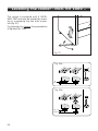
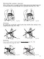
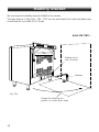
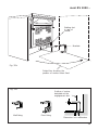
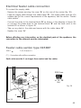
1
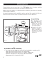
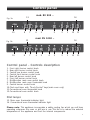
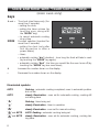
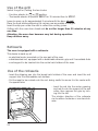
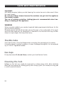
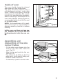
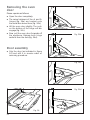
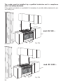
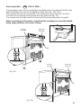
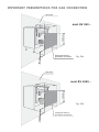
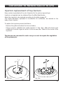
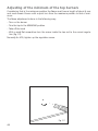
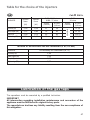
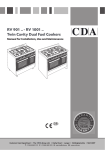
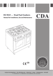
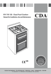
Twin cavity
dual fuel cookers
RV 900 ..
RV 1000 ..
GB
Users Operating Instructions
Installation instructions
Before operating this cooker,
please read these instructions carefully
Dear Customer
Thank you for choosing one of our appliances, carefully designed and built by
our specialist staff and thoroughly tested to satisfy your cooking requirements.
We suggest that you read this Instruction Booklet so that you will understand
fully how to operate your appliance.
Please keep the booklet handy. You may wish to refer to it at a later date.
CDA
IMPORTANT INFORMATION FOR CORRECT DISPOSAL OF
THE PRODUCT IN ACCORDANCE WITH EC DIRECTIVE
2002/96/EC.
At the end of its working life, the product must not be disposed of as
urban waste. It must be taken to a special local authority differentiated
waste collection centre or to a dealer providing this service.
Disposing of a household appliance separately avoids possible negative consequences for the environment and health deriving from inappropriate disposal and enables the constituent materials to be recovered to obtain significant savings in energy and resources. As a
reminder of the need to dispose of household appliances separately,
the product is marked with a crossed-out wheeled dustbin.
Important:
This appliance is designed and manufactured solely for the cooking of domestic
(household) food and is not suitable for any non domestic application and therefore should not be used in a commercial environment.
The appliance guarantee will be void if the appliance is used within a non domestic environment i.e. a semi commercial, commercial or communal environment.
2
Contents
Models RV 1000 .., RV 900 ..
Page Number
Introduction . . . . . . . . . . . . . . . . . . . . . . . . . . . . . . . . . . . . . . . . . . . . . . 4
Features and technical data - mod. RV 900 . . . . . . . . . . . . . . . . . . . . . . . 5
Features and technical data - mod. RV 900 . . . . . . . . . . . . . . . . . . . . . . . 6
Control panel . . . . . . . . . . . . . . . . . . . . . . . . . . . . . . . . . . . . . . . . . . . . . 7
Clock and timer with “Touch-Control” keys . . . . . . . . . . . . . . . . . . . . . . . . 8
How to use the hob burners . . . . . . . . . . . . . . . . . . . . . . . . . . . . . . . . . 11
How to use the Multifunction main oven . . . . . . . . . . . . . . . . . . . . . . . . 14
How to use the Conventional oven . . . . . . . . . . . . . . . . . . . . . . . . . . . . 20
Do’s and do not’s . . . . . . . . . . . . . . . . . . . . . . . . . . . . . . . . . . . . . . . . . . 24
Important notes . . . . . . . . . . . . . . . . . . . . . . . . . . . . . . . . . . . . . . . . . . . 25
Care and maintenance . . . . . . . . . . . . . . . . . . . . . . . . . . . . . . . . . . . . . 26
For the installer
Location . . . . . . . . . . . . . . . . . . . . . . . . . . . . . . . . . . . . . . . . . . . . . . . . 33
Fitting the adjustable feet and levelling - mod. RV 900 . . . . . . . . . . . . . 35
Levelling the cooker - mod. RV 1000 . . . . . . . . . . . . . . . . . . . . . . . . . . 36
Moving the cooker . . . . . . . . . . . . . . . . . . . . . . . . . . . . . . . . . . . . . . . . 37
Stability bracket . . . . . . . . . . . . . . . . . . . . . . . . . . . . . . . . . . . . . . . . . . . 38
Provision for ventilation . . . . . . . . . . . . . . . . . . . . . . . . . . . . . . . . . . . . . 40
Gas installation . . . . . . . . . . . . . . . . . . . . . . . . . . . . . . . . . . . . . . . . . . . 41
Gas connection . . . . . . . . . . . . . . . . . . . . . . . . . . . . . . . . . . . . . . . . . . . 42
Conversion to Natural Gas or to LPG . . . . . . . . . . . . . . . . . . . . . . . . . . . .45
Lubrication of the gas taps . . . . . . . . . . . . . . . . . . . . . . . . . . . . . . . . . . . 47
Electrical installation . . . . . . . . . . . . . . . . . . . . . . . . . . . . . . . . . . . . . . . . 48
Appliance servicing . . . . . . . . . . . . . . . . . . . . . . . . . . . . . . . . . . . . . . . . 50
Guarantee . . . . . . . . . . . . . . . . . . . . . . . . . . . . . . . . . . . . . . . . . . . . . . . 51
3
Introduction
Congratulations on your purchase of this CDA cooker which has been carefully
designed and produced to give you many years of satisfactory use.
Before using this appliance it is essential that the following instructions are carefully
read and fully understood.
We would emphasise that the installation section must be fully complied with for your
safety to ensure that you obtain the maximum benefits from your appliance.
B
Assembling
the backguard
■
Remove the two
spacers “A” and the
screw “B” from the
rear of the cooktop.
■
Assemble the backguard as shown in
figure 1 and fix it by
screwing the central
screw “B” and the
spacers “A”.
A
Fig. 1
Declaration of
CE
conformity
✓ This cooker has been designed, constructed and marketed in compliance with:
- Safety requirements of EU Directive "Gas" 90/396/EEC;
- Safety requirements of EU Directive "Low Voltage" 2006/95/EC;
- Protection requirements of EU Directive "EMC" 89/336/EEC;
- Requirements of EU Directive 93/68/EEC.
4
GB
Features and technical data
Gas burners - mod. RV 900 ..
1.
2.
3.
4.
Auxiliary burner (A)
Semi-rapid burner (SR)
Rapid burner (R)
Triple-ring burner (TR)
1,00 kW
1,75 kW
3,00 kW
3,50 kW
4
3
2
1
2
Conventional
oven
Fig. 2a
Multifunction
oven
5
Features and technical data
Gas burners - mod. RV 1000 ..
1.
2.
3.
4.
Auxiliary burner (A)
Semi-rapid burner (SR)
Rapid burner (R)
Triple-ring burner (TR)
1,00 kW
1,75 kW
3,00 kW
3,50 kW
1
3
2
4
4
2
Conventional
oven
Fig. 2b
6
Multifunction
oven
Control panel
mod. RV 900 ..
13
Fig. 3a
10
8
7
8
6
5
9
2
1
mod. RV 1000 ..
13
Fig. 3b
10
14
7
6
5
4
3
12
11
14
2
1
12
11
Control panel - Controls description
1. Front right burner control knob
2. Rear right burner control knob
3. Central rear burner control knob
4. Central front burner control knob
5. Rear left burner control knob
6. Front left burner control knob
7. Multifunction main oven switch knob
8. Multifunction main oven thermostat knob
9. Central burner control knob
10.Clock and timer with “Touch-Control” keys (main oven only)
11.Conventional oven thermostat knob
12.Conventional oven switch knob
Pilot lamps:
13. Main oven thermostat indicator light
14. Conventional oven thermostat indicator light
Please note: This appliance incorporates a safety cooling fan which you will hear
operating whenever the oven or grill are in use. This fan is to reduce the external
temperature of the appliance and cool the internal components.
7
Clock and timer with “Touch-Control” keys
(main oven only)
keys
+ and –
MODE
Touched simultaneously (for
more than 2 seconds):
• setting the clock;
• setting the timer volume (by
touching once, along with
the “MODE” key);
• to cancel automatic cooking
at any time.
Function selection (touched for
more than 2 seconds):
• setting the clock (only after
first connection or after a
power failure);
• timer;
Fig. 4
• automatic cooking “dur” (duration) - how long the food will take to cook
(by touching the “MODE” key again);
• automatic cooking “End” - the time you would like the oven turns off (by
touching the “MODE” key two more times);
+
Increases the number shown on the display
–
Decreases the number shown on the display
Illuminated symbols:
AUTO
flashing - automatic cooking completed, oven in automatic position
but not set
AUTO
steady illumination - oven set for automatic cooking, cooking still
not taking place
“
”
flashing - timer being set
“
”
steady illumination - timer in operation
“
”
steady illumination - oven set for manual cooking
“
” and AUTO
AUTO flashing - automatic cooking being set
“
” and AUTO
steady illumination - oven set for automatic cooking, cooking taking place.
8
“TOUCH-CONTROL” keys
The “touch-control” keys shall be operated by the fingers (just by touching the key).
When using touch controls it is best to use the ball of your finger rather than the tip.
The keys are automatically deactivated:
• 8 seconds after the last selection; the deactivation is indicated by an acoustic signal
(“beep”).
To reactivate just touch the “MODE” key or the “+” and “–” keys (simultaneously) for
more than 2 seconds.
Setting the clock
When first connected, or after a power failure, the digits and “AUTO” will shown on
the display. To set the clock, touch the “MODE“ key, for more than 2 seconds, and
then the “+” or “–” keys.
Important: the oven does not operate, in manual cooking, without first having set the clock.
To set the clock, with the appliance already connected, touch the “+” and “–” keys
simultaneously (for more than 2 seconds), then “+” or “–” keys.
Important:
• changing the time will delete any automatic program;
• after setting the clock, the oven starts to operate in the selected function
(manual cooking). The “ ” symbol is steady illuminated.
Using the timer
You can use the timer at any time, even when the oven is not in use.
The timer does not turn the oven off.
The timer can be set for up to 23 hours and 59 minutes.
• To set the timer, touch the “MODE” key for more than 2 seconds (the “ ” symbol
flashes), than the “+” or “–” keys.
• After about 8 seconds an acoustic signal (“beep”) will sound confirming the regulation (“ ” symbol steady illuminated).
• To check the remaining time touch the “MODE“ key for more than 2 seconds. If the
remaining time is more than a minute the display will show hours and minutes; if
less than a minute the display will show seconds.
• When the time is up, the timer will beep. Touch the “MODE” key , for more then 2
seconds, to turn it off; or press the “+” or “–” key to stop the beep and than the
“MODE” key, for more than 2 seconds, to deactivate the “ ” symbol flashing on the
display.
• Turn off the oven manually (function and thermostat knobs in the off position) if the
manual cooking has been completed.
9
Setting the timer volume
You can select from three volume levels.
• Touch the “+” and “–” keys simultaneously for more than 2 seconds.
• Touch the “MODE” key; you can read on the display the current timer volume
(“ton1”, “ton2” or “ton3”).
• Touch the “–” key to listen or change the timer volume.
• Timer volume activated: the last displayed.
• After about 8 seconds an acoustic signal (“beep”) will sound confirming the volume
setting; then the time of day will be displayed.
Automatic cooking
Use automatic cooking to automatically turn the oven on, cook, and then turn the oven
off.
1. Check the clock shows the correct time.
2. Select the function and temperature (function and temperature knobs). The oven will
come on.
3. Decide how long the food will take to cook, allowing time for preheating if necessary.
4. Touch the “MODE” key for more than 2 seconds and then touch again. “dur” will
show (duration). Using the “+” and “–” keys, set the cooking time.
5. Decide the time you would like the oven to turn off; touch the “MODE” key for more
than 2 seconds and then touch it two times again. “End” will show. Using the “+”
and “–” keys, set the cooking time.
Note: while “dur” is displayed you can change to “End” just by touching one time
the “MODE” key (within 8 seconds from the last selection).
If there is time to wait before cooking starts, the current time of day and “AUTO” will
show in the clock display. The oven will switch off but is now set for automatic cooking.
If you are already at home to turn the oven on and only want the oven to turn off automatically, start cooking as normal, then follow step 4 or step 5 to set a time to stop the
oven.
When automatic cooking starts, “ ” will be displayed and the oven will turn on.
• To see the remaining cook time, follow step 4 up to display “dur” (duration).
• To see the set stop time, follow step 5 up to display “End”.
• To cancel automatic cooking at any time, touch the “+” and “–” keys simultaneously
(for more than 2 seconds) and turn the temperature and function knobs to the off
position.
When the stop time is reached, the oven will turn off, the timer will beep and “AUTO”
will flash:
• Touch any key to stop the beeping.
• Touch the “MODE” key, for more than 2 seconds, to return the oven to the manual
mode (“ ” symbol steady illuminated on the display).
• Turn the temperature and function knobs to the off position.
Attention: after a power failure any automatic program is deleted. Turn off the
oven manually.
10
How to use the hob burners
Hob burners
Each hob burner is controlled by a separate gas tap operated by a control
knob (fig. 5) which has 3 positions
marked on the control panel, these are:
– Symbol
: tap closed (burner off)
– Symbol
: High (maximum)
– Symbol
: Low (minimum)
Push in and turn the knob anti-clockwise to the selected position.
Fig. 5
To turn the burner off, fully rotate the knob clockwise to the off position: .
The maximum setting of the control tap is for boiling, the minimum setting is for slow
cooking and simmering.
All working positions must be choosen between the maximum and minimum setting,
never between the maximum setting and the “OFF” position.
Electric ignition
The sparks generated by the electrodes close to the burners will ignite the choosen
burner. Whenever the lighting of the burners is difficult due to peculiar conditions of
the gas features or supply, it is advised to repeat the ignition with the knob on “minimum” position.
Lighting of the hob burners
To ignite the burner, the following instructions are to be followed:
1) Lightly press and turn the knob anti-clockwise, and position the knob indicator to the
symbol
printed on the control panel (fig. 5).
2) Press the knob to operate the electric ignition; or, in the case of a mains failure light
the burner with a match or lighted taper.
3) Adjust the burner according to the setting required.
11
Choice of burner
The burner must be choosen according to the diameter of the pans and energy
required.
Burners
Pan diameter
Auxiliary
Semi-rapid
Rapid (RV 900 .. model)
Rapid (RV 1000 .. model)
Triple-ring
Wok
12 ÷ 14 cm
16 ÷ 24 cm
24 ÷ 26 cm
24 ÷ 24 cm
26 ÷ 28 cm
max 36 cm
Fig. 6
do not use pans with concave or convex bases
Saucepans with handles which are excessively heavy, in relationship to the weight of
the pan, are safer as they are less likely to tip. Pans which are positioned centrally on
burners are more stable than those which are offset.
It is far safer to position the pan handles in such a way that they cannot be accidentally
knocked.
When deep fat frying fill the pan only one third full of oil.
DO NOT cover the pan with a lid and DO NOT leave the pan unattended.
In the unfortunate event of a fire, leave the pan where it is and turn off all controls.
Place a damp cloth or correct fitting lid over the pan to smother the flames.
DO NOT use water on the fire.
Leave the pan to cool for at least 30 minutes.
AIR FLOW
(cooling fan)
AIR FLOW
(cooling fan)
AIR FLOW
(cooling fan)
CORRECT USE OF RAPID BURNER (mod. RV 1000 .. only)
Fig. 7
12
Correct use of triple-ring burner
The flat-bottomed pans are to be placed directly onto the pan-support.
To use the WOK you need to place the proper stand in order to avoid any faulty
operation of the triple-ring burner (Fig. 8a - 8b).
IMPORTANT:
The wok pan stand (fig. 8b) MUST BE PLACED ONLY over the pan-rest for the triplering burner.
WRONG
CORRECT
Fig. 8a
Fig. 8b
13
How to use the Multifunction main oven
General features
As its name indicates, this is an oven that presents particular features from an operational point of view.
In fact, it is possible to insert 7 different programs to satisfy every cooking need.
The 7 positions, thermostatically controlled, are obtained by 4 heating elements which
are:
– Bottom element
1200 W
– Top element
1000 W
– Grill element
2000 W
– Circular element
2200 W
Note:
Upon first use, it is advisable to operate the oven for 30 minutes in the position
and for
another 30 minutes at the maximum temperature (thermostat knob on position 250) in the
and
, to eliminate possible traces of grease on the heating elements.
positions
Clean the oven and accessories with warm water and washing-up liquid.
WARNING:
The door is hot, use the handle.
ATTENTION - MOST IMPORTANT
Pay special attention not to touch
the hot heating element inside the
oven cavity.
Operating principles
Heating and cooking in the MULTI-FUNCTION oven are obtained in the following
ways:
a. by normal convection
The heat is produced by the upper and lower heating elements.
b. by forced convection
A fan sucks in the air contained in the oven muffle, which sends it through the
circular heating element and then sends it back through the muffle. Before the hot
air is sucked back again by the fan to repeat the described cycle, it envelops the
food in the oven, provoking a complete and rapid cooking.
It is possible to cook several dishes simultaneously.
c. by semi-forced convection
The heat produced by the upper and lower heating elements is distributed
throughout the oven by the fan.
d. by radiation
The heat is radiated by the infra red grill element.
e. by radiation and ventilation
The irradiated heat from the infra red grill element is distributed throughout the
oven by the fan.
f. by ventilation
The food is defrosted by using the fan only function without heat.
14
Fig. 9
Fig. 10
Thermostat knob
(Fig. 9)
This only sets the cooking temperature and does not switch the oven on.
Rotate clockwise until the required temperature is reached (from 50 to 250°C).
The light between the thermostat and the function selector will illuminate when the
oven is switched on and turns off when the ovenahe correct temperature.
The light will cycle on and off during cooking in line with the oven temperature.
Function selector knob (Fig. 10)
Rotate the knob clockwise to set the oven for one of the following functions.
Oven light
By setting the knob to this position, only the oven light comes on.
It remains on in all the cooking modes.
Traditional convection cooking
The upper and lower heating elements come on. The heat is dispersed by natural convection and the temperature must be set to between 50° and 250°C via the thermostat knob.
The oven must be preheated before cooking.
Recommended for:
Food that requires the same degree of cooking both inside and out, for example
roasts, spare pork ribs, meringues etc.
15
Grilling
The infrared grill element comes on. The heat is dispersed by radiation.
Use with the oven door closed and the thermostat knob to position 225°C for max
15 minutes, then to position 175°C.
For cooking hints, see the chapter “USE OF THE GRILL”.
Recommended for:
Intense grilling, browning, cooking au gratin and toasting etc.
It is recommended that you do not grill for longer than 30 minutes at any
one time.
Caution: the oven door becomes very hot during operation. Keep children
well out of reach.
Defrosting frozen foods
Only the oven fan comes on. Use with the thermostat knob set to “ ” - other positions
have no effect. The food is thawed by ventilation without heating.
Recommended for:
Quick thawing of frozen foods; one kg requires approximately 1 hour.
Thawing times vary according to the quantity and type of food to be thawed.
Hot air cooking
The circular element and fan come on. The heat is dispersed by forced convection and
the temperature can be regulated to between 50° and 250°C via the thermostat knob.
The oven does not require preheating.
Recommended for:
Food which has to be well-cooked outside and soft or rosy inside, for example
lasagne, lamb, roast beef, whole fish etc.
16
Ventilated grill cooking
The infrared grill element and the fan come on. The heat is dispersed mainly by radiation and the fan then distributes it all over the oven.
Use with the door closed. The temperature can be regulated via the thermostat
knob to between 50° and 175° max.
The oven must be preheated for approximately 5 minutes. For cooking hints, see the
chapter “GRILLING AND AU GRATIN.
Recommended for:
Grilling where quick browning on the outside is required to keep the juices in.
For example: veal steaks, chops, hamburgers etc.
It is recommended that you do not grill for longer than 30 minutes at any
one time.
Caution: the oven door becomes very hot during operation. Keep children
well out of reach.
Maintaining temperature after cooking or slowly
heating foods
The upper heating element, the circular element and the fan come on.
The heat is dispersed by forced convection with greater intensity in the upper part.
The temperature can be set to between 50° and 150°C via the thermostat knob.
Recommended for:
Keeping food warm after any type of cooking. Slow heating of cooked food.
Convection cooking with ventilation
The upper and lower heating elements come on and the fan.
The heat coming from above and below is dispersed by convection with ventilation.
The temperature can be set to between 50° and 250°C via the thermostat knob.
Recommended for:
Voluminous dishes and large quantities which require the same degree of cooking
both inside and out, for example rolled roasts, turkey, roast legs, cakes etc.
17
Cooking advice
Sterilization
Sterilization of foods to be conserved, in full and hermetically sealed jars, is done in the
following way:
a.
b.
c.
d.
Set the switch to position
.
Set the thermostat knob to position 185 °C and preheat the oven.
Fill the dripping pan with hot water.
Set the jars onto the dripping pan making sure they do not touch each other and
the door and set the thermostat knob to position 135 °C.
When sterilization has begun, that is, when the contents of the jars start to bubble,
turn off the oven and let cool.
Regeneration
Set the switch to position
and the thermostat knob to position 150° C.
Bread becomes fragrant again if wet with a few drops of water and put into the oven
for about 10 minutes at the highest temperature.
Simultaneous cooking of different foods
The MULTI-FUNCTION oven set on position
and
gives a simultaneous heterogeneous cooking of different foods. Different foods such as fish, cake and meat can be
cooked together without mixing the smells and flavors together.
This is possible since the fats and vapors are oxidized while passing through the electrical element and therefore are not deposited onto the foods.
The only precaution to follow are:
– The cooking temperatures of the different foods must be as close to as possible, with
a maximum difference of 20° - 25 °C.
– The introduction of the different dishes in the oven must be done at different times in
relation to the cooking times of each one.
The time and energy saved with this type of cooking is obvious.
18
Grilling and “au gratin”
Grilling may be done without the roasting jack on position
of the switch, because
the hot air completely envelops the food that is to be cooked.
Set the thermostat to position 175 °C and after having preheated the oven, simply
place the food on the rack.
Close the door and let the oven operate with the thermostat on position 175 °C, until
grilling is done.
Adding a few dabs of butter before the end of the cooking time gives the golden “au
gratin” effect.
It is recommended that you do not grill for longer than 30 minutes at any
one time.
Caution: the oven door becomes very hot during operation. Keep children
well out of reach.
Roasting
To obtain classical roasting, it is necessary to remember:
– that it is advisable to maintain a temperature between 180° and 200 °C.
– that the cooking time depends on the quantity and the type of foods.
Use of the grill
Preheat the oven for about 5 minutes.
Introduce the food to be cooked, positioning the rack as close to the grill as possible.
The dripping pan should be placed under the rack to catch the cooking juices and
fats.
Grilling with the oven door closed.
Do not grill for longer than 30 minutes at any one time.
Caution: the oven door becomes very hot during operation. Keep children
well out of reach.
19
How to use the Conventional oven
General features
As its name indicates, this is an oven that presents particular features from an operational point of view.
The conventional oven is provided with 3 heating elements which are:
– Bottom element
– Top element
– Grill element
800 W
700 W
1450 W
Note:
Upon first use, it is advisable to operate the oven at the maximum temperature (thermostat knob on position 250) for 60 minutes in the position
and for another 15
minutes in the position
to eliminate possible traces of grease on the heating elements.
WARNING:
The door is hot, use the handle.
ATTENTION - MOST IMPORTANT
Pay special attention not to touch
the hot heating element inside the
oven cavity.
Thermostat knob (Fig. 12)
This only sets the cooking temperature and does not switch the oven on.
Rotate clockwise until the required temperature is reached (from 50 to 250°C).
The light between the thermostat and the function selector will illuminate when the
oven is switched on and turns off when the oven reaches the correct temperature.
The light will cycle on and off during cooking in line with the oven temperature.
Fig. 11
20
Fig. 12
Function selector knob (Fig. 11)
Rotate the knob clockwise to set the oven for one of the following functions.
Oven light
By setting the knob to this position, only the oven light comes on.
It remains on in all the cooking modes.
Traditional convection cooking
The upper and lower heating elements come on.
The heat is dispersed by natural convection and the temperature must be set to
between 50° and 250°C via the thermostat knob. The oven must be preheated before
cooking.
In the
position the rotisserie motor come on for cooking with the rotisserie.
Recommended for:
Food that requires the same degree of cooking both inside and out, for example
roasts, spare pork ribs, meringues etc.
Traditional grilling
The infrared electrical resistance comes on.
The heat is diffused by radiation.
Use with the oven door closed and the thermostat knob to position 225°C for 15
minutes then to 175°C.
In the
position the rotisserie motor come on for cooking with the rotisserie.
For cooking hints, see the chapter “USE OF THE GRILL”.
Recommended for:
Intense grilling, browning, cooking au gratin and toasting etc.
It is recommended that you do not grill for longer than 30 minutes at any
one time.
Attention: the oven door becomes very hot during operation.
Keep children away.
21
Use of the grill
Switch the grill on, setting the two knobs:
– Function selector to
or
position.
– Thermostat selector to position 225°C for 15 minutes then to 175°C.
Leave to warm up for approximately 5 minutes with the door closed.
Place the food inside positioning the rack as near as possible to the grill.
Insert the drip pan under the rack to collect the cooking juices.
Grilling with the oven door closed and do not for longer than 30 minutes at any
one time.
Attention: the oven door becomes very hot during operation.
Keep children away.
Rotisserie
The oven is equipped with a rotisserie.
This device is made up of:
– an electrical motor mounted on the rear part of the oven
– a stainless steel rod, equipped with a detachable athermic grip and 2 recordable forks
– a rod support to be inserted into the central rack holders of the oven.
Use of the rotisserie
– Insert the dripping pan into the lowest rack holders of the oven and insert the rod
support into the intermediate rack holders.
– Put the meat to be cooked onto the rod, being careful to secure it in the center with
the special forks.
– Insert the rod into the motor opening
and rest it onto the support of the spit
collar; then remove the grip by turning it to the left.
The rotation direction of the rotisserie
can be either clockwise or counter-clockwise.
Fig. 13
22
Use of special dish rack
This special shelf can be used as dish rack or turning over, as normal shelf for oven
cooking.
It must be inserted between the guides of the lateral racks.
Using the special shelf as a dish rack
Slide in the shelf on the guides, on the lower level of the lateral racks.
The prongs where the plates are to be inserted, must be turned upwards.
The shelf must be fitted so that the safety catch, which stops it sliding out, faces the
bottom of the oven (see detail of figure 14).
The plates must be positioned as indicated in figure 14.
To facilitate this operation, pull the special rack up to the safety lock.
KEEP ATTENTION: Plates are hot after warming. It is advisable to handle the
plates using oven gloves.
Using the special rack for normal cooking
Slide in the shelf on the guides: the safety catch must be turned toward the oven base
(see detail of figure 15).
The flat surface can be used to put cooking pans or food directly on the rack - the dripping pan should be placed under the rack to catch the cooking juices and fats.
Fig. 14
Fig. 15
23
Do’s and do not’s
Do’s and do not’s
• Do always grill with the oven door closed.
• Do read the user instructions carefully before using the cooker for first time.
• Do allow the oven to heat for one and a half hours, before using for the first time, in
order to expel any smell from the new oven insulation, without the introduction of
food.
• Do clean your oven regularly.
• Do remove spills as soon as they occur.
• Do always use oven gloves when removing food shelves and trays from the oven.
• Do not allow children near the cooker when in use.
• Do not allow fat or oils to build up in the oven trays, or oven base.
• Do not place cooking utensils or plates directly onto the oven base.
• Do not grill food containing fat without using the grid.
• Do not cover the grilling grid with aluminium-foil.
• Do not use the oven tray for roasting.
• Do not place hot enamel parts in water. Leave them to cool first.
• Do not allow vinegar, coffee, milk, saltwater, lemon or tomato juice to remain in contact with enamel parts (inside the oven and on the oven tray).
• Do not use abrasive cleaners or powders that will scratch the surface of the stainless
steel and the enamel.
• Do not attempt to repair the internal workings of your cooker.
• Do remove the protective film before the first use.
• Fire risk! Do not store flammable material in the ovens and in the storage compartment (RV 900 .. model) or bottom drawer (RV 1000 .. model).
For your safety
The product should only be used for its intended purpose which is for the cooking of
domestic foodstuffs.
Under no circumstances should any external covers be removed for servicing or maintenance except by suitably qualified personnel.
Attention
The appliance gets very hot, mainly around the cooking areas. It is very
important that children are not left alone in the kitchen when you are cooking.
24
Important notes
Installation, and any demonstration, information or adjustments are not included in
the warranty.
The cooker must be installed by a qualified person in accordance with the relevant
Standards.
In the UK C.O.R.G.I registered installers are authorised to undertake the installation and
service work in compliance with the applicable regulations.
25
Care and maintenance
Important:
As a safety measure, before you start cleaning the cooker be sure to disconnect it from
the mains supply.
Do not use a steam cleaner because the moisture can get into the appliance
thus make it unsafe.
The use of suitable protective clothing/gloves is recommended when handling or cleaning of this appliance.
WARNING
When correctly installed, your product meets all safety requirements laid down for this
type of product category.
However special care should be taken around the rear or the underneath of the appliance as these areas are not designed or intended to be touched and may contain
sharp or rough edges, that may cause injury.
Flexible tube
From time to time, check the flexible tube connecting the gas supply to the cooker.
It must be always in perfect condition; in case of damage arrange for it to be replaced
by a C.O.R.G.I. registered installer.
Gas taps
If a tap becomes stiff, do not force; contact your local Service Centre.
Cleaning the hob
Spillage on the hob can usually be removed by a damp soapy cloth. More obstinate
stains can be removed by rubbing gently with a soapy nylon (non metal) scouring pad
or mild household cleaner.
26
Enamelled parts
All the enamelled parts must be cleaned with a sponge and soapy water only or other
non-abrasive products.
Dry preferably with a microfibre or soft cloth.
Stainless steel, aluminium, painted parts and silkscreen printed surfaces
Clean using an appropriate product. Always dry thoroughly.
Stainless steel surfaces: can be cleaned with an appropriate stainless steel cleaner.
IMPORTANT: these parts must be cleaned very carefully to avoid scratching and abrasion. You are advised to use a soft cloth and neutral soap.
CAUTION: Do not use abrasive substances or non-neutral detergents as these will
irreparably damage the surface.
Glass control panel
Clean using an appropriate product.
Always dry thoroughly.
Do not use harsh abrasive cleaners or sharp metal scrapers to clean the control panel
since they can scratch the surface, which may result in shattering of the glass.
Changing the oven light
1. Disconnect the electrical power supply (for example, by switching off the main
power switch).
2. Unscrew the light cover
3. Fit a new bulb.
4. Refit the cover.
Note:
Use only bulbs designed to resist up to 300°C with the following characteristics: 230 V,
type E14 and same power (check watt power as stamped in the bulb itself) of the
replaced bulb.
27
Burners
They can be removed and washed only
with soapy water.
Detergents can be used but must not be
abrasive or corrosive.
Do not use abrasive sponges or pads.
Do not put in dishwasher.
After each cleaning, make sure that the
burner-caps, as well as the burners, have
been well wiped off and CORRECTLY
POSITIONED.
It is essential to check that the burner
flame distributor F and the cap C has
been correctly positioned (see fig. 16) failure to do so can cause serious problems.
Check that the electrode “S” (fig. 16) is
always clean to ensure trouble-free sparking.
C
F
S
Note:
The electrode “S” must be very carefully
cleaned.
To avoid damage to the electric ignition do not use it when the burners are
not in place.
Fig. 16
Triple ring burner
The triple ring burner must be correctly positioned (see figs. 17-18); the burner rib
must be enter in their logement as shown by the arrow.
The burner correctly positioned must not rotate (fig. 18).
Then position the cap A and the ring B (fig. 18).
A
Fig. 17
28
Fig. 18
B
Oven doors - removing
the inner pane of glass
The inner pane of glass can easily be
removed for cleaning.
Removing the inner pane
– Open the door to the full extent.
– Gently pull out the inner pane of glass
(Fig. 19a).
– Clean the glass with an appropriate
cleaner.
– Dry thoroughly, and place the pane on
a soft surface.
– Now you can also clean the inside of
the outer glass.
Do not use harsh abrasive cleaners or
sharp metal scrapers to clean the
panes of glass since they can scratch
the surface, which may result in shattering of the glass.
Reassembling the inner
pane
– Check the correct positioning of the
no.4 (four) silicon rubbers D (fig. 19b).
– Check that you are holding the pane
the correct way. You should be able to
read the wording on it as it faces you.
– Insert the inner pane in the left E and
right F side guides (fig. 19c) and gently
let it slide up to the retainers H (fig.
19d).
It is normal the opened gap between the
top edge of the inner glass and the top of
the door. This allows the cooling air
circulation.
Fig. 19a
D
Fig. 19b
E
F
Fig. 19c
H
Fig. 19d
29
Storage compartment (Model RV 900 ..)
– The storage compartment is accessible through the pivoting panel.
Attention: Do not store flammable material in the ovens, or the storage compartment.
Fig. 20
Drawer (Model RV 1000 ..)
– The drawer (fig. 21) comes out like a normal drawer.
Attention: Do not store flammable material in the ovens, or the drawer.
Fig. 21
30
Inside of oven
The oven should always be cleaned
after use when it has cooled down.
The cavity should be cleaned using a
mild detergent solution and warm
water. Suitable proprietary chemical
cleaners may be used after first consulting with the manufacturers recommendations and testing a small sample of the
oven cavity. Abrasive cleaning agents or
scouring pads/cloths should not be used
on the cavity surface.
NOTE: The manufacturers of this appliance will accept no responsibility for
damage caused by chemical or abrasive
cleaning.
Fig. 22
Let the oven cool down and pay special attention no to touch the hot
heating elements inside the oven cavity.
Assembling and
dismantling of the side
runner frames
– Fit the side runner frames into the
holes on the side walls inside the
oven (Fig. 22).
– Slide the tray and rack into the runners (Fig. 23).
The rack must be fitted so that the
safety catch, which stops it sliding out,
faces the inside of the oven.
– To dismantle, operate in reverse order.
Fig. 23
31
Removing the oven
door
Fig. 24a
Please operate as follows:
●
●
●
●
Open the door completely.
The swivel retainers of the rh and lh
hinges (fig. 24a) are hooked onto
the metal bar above them (fig. 24b).
Lift the oven door slightly. The noch
on the bottom of the hinge will disengage (fig. 24c).
Now pull the oven door forwards off
the appliance. Release both hinge
sections from the slots (fig. 24d).
Fig. 24b
Door assembly
●
Grip the door (as indicated in figure
24) and refit it in reverse order of
removing procedure.
Fig. 24c
Fig. 24d
Fig. 24
32
FOR THE INSTALLER
Location
This cooker has class “2/1” overheating protection so that it can be installed
next to a cabinet.
The appliance may be installed in a kitchen, Kitchen/diner or a bed sitting room, but
not in a room or space containing a bath or a shower.
The appliance must not be installed in a bed-sitting room of less than 20 m3.
The appliance is designed and approved for domestic use only and should not be
installed in a commercial, semi commercial or communal environment.
Your product will not be guaranteed if installed in any of the above environments and
could affect any third party or public liability insurances you may have.
If the cooker is installed adjacent to furniture which is higher than the gas hob cooktop, a gap of at least 200 mm must be left between the side of the cooker and the furniture.
The furniture walls adjacent to the cooker must be made of material resistant to heat.
The veneered synthetic material and the glue used must be resistant to a temperature
of 90°C in order to avoid ungluing or deformations.
Curtains must not be fitted immediatly behind appliance or within 500 mm of the sides.
It is essential that the cooker is positioned as stated in Figs. 25a - 25b.
33
650 mm
450 mm
The cooker must be installed by a qualified technician and in compliance
with local safety standards.
If the cooker is located on a pedestal it is necessary to provide safety measures to prevent falling out.
200 mm
mod. RV 900 ..
500 mm
Fig. 25a
450 mm
650 mm
ent
air v
200 mm
mod. RV 1000 ..
500 mm
ent
air v
34
Fig. 25b
Fitting the adjustable feet and levelling
the cooker - mod. RV 900 ..
The adjustable feet must be fitted
to the base of the cooker before
use.
Rest the rear of the cooker an a
piece of the polystyrene packaging
exposing the base for the fitting of
the feet.
Fig. 26
Fit the 4 legs by screwing them
tight into the support base as
shown in picture 26a.
Fig. 26a
Levelling the cooker
The cooker may be levelled by screwing the lower ends of the feet IN or
OUT (fig. 26b).
Fig. 26b
35
Levelling the cooker - mod. RV 1000 ..
The cooker is equipped with 4 LEVELLING FEET and may be levelled by screwing or unscrewing the feet with a spanner (fig. 27).
It is important to observe the prescriptions
of figures 28a - 28b.
Fig. 27
Fig. 28a
0
+8
mm
Fig. 28b
+ 8 mm
+ 35 mm
36
Moving the cooker - Warning
When raising cooker to upright position always ensure two people carry out
this manoeuvre to prevent damage to the adjustable feet (figs. 29a - 29b).
Fig. 29a
Fig. 29b
Warning
Be carefull: do not lift the cooker by the door handle when raising to the
upright position (figs. 30a - 30b).
Fig. 30a
Fig. 30b
Warning
When moving cooker to its final position DO NOT DRAG (figs. 31a - 31b).
Lift feet clear of floor (figs. 29a - 29b).
Fig. 31a
Fig. 31b
37
Stability bracket
We recommend a stability bracket is fitted to the cooker.
The type shown in figs. 32a - 32b - 32C can be purchased from most plumbers merchants and do it yourself (D.I.Y.) shops.
mod. RV 900 ..
Existing slot in
rear of cooker
Brackets
Fig. 32a
Dotted line showing the
position of cooker when fixed
38
mod. RV 1000 ..
Existing slot
in rear of
cooker
Brackets
Fig. 32b
Dotted line showing the
position of cooker when fixed
Fig. 32c
3
Outline of cooker
backplate at the
engagement slot
Wall fixing
Floor fixing
Dimension is in millimetres
39
Provison for ventilation
✓ The appliance should be installed into a room or space with an air supply in accor-
dance with BS 5440-2: 2000.
✓ For rooms with a volume of less than 5 m3 - permanent ventilation of 100 cm2 free
area will be required.
✓ For rooms with a volume of between 5 m3 and 10 m3 a permanent ventilation of
50 cm2 free area will be required unless the room has a door which opens directly to
the outside air in which case no permanent ventilation is required.
✓ For rooms with a volume greater than 10 m3 - no permanent ventilation is required.
NB. Regardless of room size, all rooms containing the appliance must have
direct access to the outside air via an openable window or equivalent.
✓ Where there are other fuel burning appliances in the same room, BS 5440-2: 2000
should be consulted to determine the correct amount of free area ventilation requirements.
✓ The above requirements allow also for use of a gas oven and grill but if there are
other gas burning appliances in the same room, consult a qualified engineer.
40
Gas installation
IMPORTANT NOTE
This appliance is supplied for use on NATURAL GAS or LPG (check the gas regulation
label attached on the appliance).
✓ Appliances supplied for use on NATURAL GAS: they are adjusted for this gas only and
cannot be used on any other gas (LPG) without modification. The appliances are
manufactured for conversion to LPG.
✓ Appliances supplied for use on LPG: they are adjusted for this gas only and cannot
be used on any other gas (NATURAL GAS) without modification. The appliances are
manufactured for conversion to NATURAL GAS.
If the NATURAL GAS/LPG conversion kit is not supplied with the appliance this kit can
be purchased by contacting the After-Sales Service.
INSTALLATION & SERVICE REGULATIONS (UNITED KINGDOM)
It is a legal requirement that all gas appliances are Installed & Serviced by a competent
person in accordance with the current editions of the following Standards &
Regulations or those regulations appropriate to the geographical region in which they
are to be installed:
✓ Gas Safety (Installation & Use) Regulations
✓ Building Regulations
✓ British Standards
✓ Regulations for Electrical Installation
Installation and service of any gas product must be made by a suitably qualified person
competent on the type of product being installed or serviced and holding a valid
certificate of competence for the work being carried out. Currently the proof of
competence is the Accredited Certification Scheme (ACS) or S/NVQ that has been
aligned to the ACS.
It is also a requirement that all businesses or self employed installers are members of a
class of person approved by the Health and Safety Executive. Currently the only body
with such approval is CORGI.
Failure to install the appliance correctly could invalidate any manufacturers warranty
and lead to prosecution under the above quoted regulation.
41
Gas connection
The installation of the gas appliance to Natural Gas or LP Gas must be carried out by a
C.O.R.G.I. registered installer. Installers shall take due account of the provisions of the
relevant British Standards Code of Practice, the Gas Safety Regulations and the Building
Standards (Scotland)(Consolidation) Regulations issued by the Scottish Development
Department.
Installation to Natural Gas
Installation to Natural Gas must conform to the Code of Practice, etc.
The supply pressure for Natural Gas is 20 mbar.
The installation must conform to the relevant British Standards.
Installation to LP Gas
When operating on Butane gas a supply pressure of 28-30 mbar is required. When
using Propane gas a supply pressure of 37 mbar is required.
The installation must conform to the relevant British Standards.
Warning: Only a C.O.R.G.I. registered installer, also with technical knowledge of electricity should install the appliance. He should observe the Regulations and Codes of
Practice governing such installation of gas appliances.
Note: It is recommended that the gas connection to the appliance is installed with a
flexible connecting tube made to BS5386.
Notes:
✓ Flexible hoses can be used where the sited ambient temperature of the
hose does not exceed 70°C. These hoses must be manufactured in
accordance with BS669 part 1 and be of the correct construction for the
type of gas being used.
✓ Gas hoses designed for natural gas MUST NOT be used for supplying LPG
gas (LPG gas hoses can be identified by a either a red band or stripe on
the rubber outer coating of the hose).
The hose should not be crushed or trapped or be in contact with sharp or
abrasive edges.
Using a suitable leak detection fluid solution (e.g. Rocol) check each gas connection
one at a time by brushing the solution over the connection.
The presence of bubbles will indicate a leak.
If there is a leak, tighten the fitting and then recheck for leaks.
IMPORTANT!
Do not use a naked flame to test for leaks.
42
GB
Gas connection
Cat: II 2H3+
The gas supply must use the nearest gas inlet pipe which is located at the left or the
right hand side at the rear of the appliance (figs. 33a, 33b, 35a, 35b).
The hose should also be connected in such away that it does not touch the floor.
To screw the connecting tube operate with two spanners (fig. 34).
The unused end inlet pipe must be closed with the plug interposing the gasket.
After connecting to the mains, check that the coupling are correctly sealed,
using soapy solution, but never a flame.
Left gas
inlet pipe
Right gas
inlet pipe
Fig. 34
Plug
1/2” BSP (male)
Left gas
inlet pipe
Right gas
inlet pipe
Fig. 33a
Plug
1/2” BSP (male)
Fig. 33b
43
IMPORTANT PRESCRIPTIONS FOR GAS CONNECTION
Rear wall
700 mm
mod. RV 900 ..
Fig. 35a
200 mm
Suggested area for
gas mains connection
Rear wall
700 mm
mod. RV 1000 ..
Fig. 35b
200 mm
Suggested area for
gas mains connection
Conversion to Natural Gas or to LPG
Injectors replacement of top burners
Every cooker is provided with a set of injectors for the various types of gas.
Injectors not supplied can be obtained from the After-Sales Service.
Select the injectors to be replaced according to the table at page 47.
The nozzle diameters, expressed in hundredths of a millimetre, are marked on the
body of each injector.
To replace the injectors proceed as follows:
–
Remove the grids and extract the burner bodies.
–
Using a wrench, substitute the nozzle injectors “J” (Fig. 36a - 36b) with those most
suitable for the kind of gas for which it is to be used (see “Table for the choice of the
injectors”).
The burners are conceived in such a way so as not to require the regulation
of the primary air.
J
J
Fig. 36a
Fig. 36b
45
Adjusting of the minimum of the top burners
Considering that in the minimum position the flame must have a length of about 4 mm
and must remain lit even with a quick turn from the maximum position to that of minimum.
The flame adjustment is done in the following way:
– Turn on the burner
– Tum the tap to the MINIMUM position
– Take off the knob
– With a small flat screwdriver turn the screw inside the tap rod to the correct regulation (fig. 37).
Normally for LPG, tighten up the regulation screw.
Fig. 37
46
Table for the choice of the injectors
GB
Cat:
G 30 - 28-30 mbar
G 31 - 37 mbar
Reduced
Power
[kW]
[kW]
By-pass
[1/100 mm]
[1/100 mm]
Auxiliary (A)
1,00
0,30
27
50
Semi-rapid (SR)
1,75
0,45
32
65
Rapid (R)
3,00
0,75
42
85
Triple-ring (TR)
3,50
1,50
65
95
INCREASE
BURNERS
Ø injector
OF AIR NECESSARY FOR GAS COMBUSTION
Ø injector
By-pass
[1/100 mm]
[1/100 mm]
72 (X)
adjustable
Nominal
Power
BURNERS
II 2H3+
G 20
20 mbar
97 (Z)
115 (Y)
135 (T)
(2 m3/h x kW)
Air necessary for combustion [m3/h]
Auxiliary (A)
2,00
Semi-rapid (SR)
3,50
Rapid (R)
6,00
Triple-ring (TR)
7,00
Lubrication of the gas taps
The operations must be executed by a qualified technician.
IMPORTANT
All intervention regarding installation maintenance and conversion of the
appliance must be fulfilled with original factory parts.
The manufacturer declines any liability resulting from the non-compliance of
this obligation.
47
Electrical installation
For your safety please read the following information:
IMPORTANT: The cooker must be installed in accordance with the manufacturer’s
instructions.
Incorrect installation, for which the manufacturer accepts no responsibility, may
cause damage to persons, animals and things.
General
– Connection to the mains must be carried out by qualified personnel in accordance
with current regulations.
– The appliance must be connected to the mains checking that the voltage corresponds to the value given in the rating plate and that the electrical cable sections
can withstand the load specified on the plate.
– The appliance can be connected directly to the mains placing an omnipolar switch
with minimum opening between the contacts of 3 mm between the appliance and
the mains.
– The power supply cable must not touch the hot parts and must be positioned so
that it does not exceed 75°C at any point.
– Once the appliance has been installed, the switch must always be accessible.
– If the power supply cable is damaged it must be substituted by a suitable cable.
N.B. For connection to the mains, do not use adapters, reducers or branching devices as they can cause overheating and burning.
If the installation requires alterations to the domestic electrical system call an expert.
He should also check that the electrical system is suitable for the power absorbed by
the appliance.
IMPORTANT: this cooker must be connected to a suitable double pole control unit
adjacent to the cooker.
No diversity can be applied to this control unit.
The connection of the appliance to earth is mandatory.
The manufacturer declines all responsability for any inconvenience resulting from the
inobservance of this condition.
48
Electrical feeder cable connection
To connect the supply cable:
- Remove the screws securing the cover “A” on the rear of the cooker (fig. 38).
- Feed the supply cable through the cable clamp “D”. The supply cable must be of a
suitable size for the current requirements of the appliance; see the section “Feeder
cable section”.
- Connect the wires to the terminal block “B” as shown in the diagram in figure 39;
or connect the phase wires to the terminal block “B” and the earth wire to the
terminal PE as shown in figure 38.
- Take up any slack in the cable and secure with the cable clamp “D”.
- Replace the cover “A”.
Before effecting any intervention on the electrical parts of the appliance, the
connection to the network must be interrupted.
Feeder cable section type H05RRF
3 x 2,5 mm2 (**)
230 V
(**) – Connection with wall box connection.
Earth cable must be 2 cm longer than neutral and live cables.
230 V
PE
N
L
B
D
L1 N PE
(L2)
Fig. 39
A
Fig. 38
49
Appliance servicing
CDA provide a quality and effective after-sales service to cover all your
servicing needs.
Please attach your receipt to this page for safekeeping.
Please help us to help you by having the following information available
when booking a service-call:
1. Model type, make and model – see the product data plate.
2. Evidence of installation / purchase date
3. Retailer where appliance was purchased
4. Clear and concise details of the fault
5. Full address including postcode and any contact phone numbers
Contact telephone numbers
CDA Customer Care Department
• Telephone: 01949 862012
• Fax: 01949 862003
• Email: [email protected]
50
Guarantee
CDA appliances carry a five-year parts and a one-year labour guarantee.
CDA will repair or replace any defect or part attributable to faulty material or workmanship. Within the first year this will be free of both labour and parts charges. After the
first year and within five years, the parts will be supplied free of charge provided that
the repair is carried out by an agent authorised by CDA and the labour will be charged
at the commercial rate applicable at the time of repair.
The appliance must have been installed by a suitably qualified person and in accordance with the manufacturer’s instructions and current legislation. The guarantee does
not cover faults caused by the incorrect fitting of appliances.
Limit of Cover
• The guarantee does not cover cosmetic damage e.g. discolouration or oxidisation.
• Proof of purchase or installation date must be produced before a service-call will be
booked.
• The appliance must be used for domestic purposes only. Appliances used for commercial or professional purposes are not covered by the guarantee. Commercial warranty is available at extra cost.
• The appliance must not be modified or tampered with or repair attempted by any
unauthorised person.
• The guarantee does not cover damage caused in transit or by misuse, accident,
abuse or neglect.
• The guarantee does not cover routine maintenance.
• Use of parts not supplied or recommended by |C|D|A| will invalidate the warranty.
• Rubber seals, filters, removable glass parts, control knobs and buttons, fuses and
light bulbs will need replacing periodically and are not covered by the guarantee.
• Second-hand or reconditioned appliances are not covered by the guarantee.
The conditions under which this guarantee is offered are in addition to the statutory
rights of the domestic purchaser and these statutory rights are not affected by this
guarantee.
CDA reserve the right to change specification without prior notice.
51
Descriptions and illustrations in this booklet are given as simply indicative.
The manufacturer reserves the right, considering the characteristics of the models described here, at
any time and without notice, to make eventual necessary modifications for their construction or for
commercial needs.
Cod. 1103127
ß3
RV 1000 .., RV 900 .. cookers
The
Group Ltd
Harby Road Langar Nottingham NG13 9HY UK
VAT No : 528 7168 19 Registered in England : 2621460
●
●
●
●
●