1
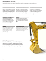
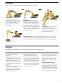
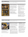
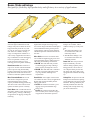
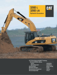
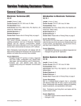
345C L
®
Hydraulic Excavator
Cat® C13 Diesel Engine with ACERT™ Technology
Net Power (ISO 9249) at 1800 rpm
239 kW/325 hp
Operating Weight
48 800 to 52 300 kg
Maximum Travel Speed
4.4 km/h
Maximum Reach
11.7 m
Maximum Digging Depth
7.5 m
345C L Hydraulic Excavator
High performance and rugged durability combine to maximize your productivity.
Engine
Application and System Match
Operator Station
The Cat C13 engine has state-of-the-art
ACERT™ technology to meet emission
regulations with exceptional performance
capabilities, fuel efficiency and proven
reliability. pg. 4
The 345C L is designed for matched
performance with Cat articulated trucks.
Five to six passes under two minutes,
matched to the Cat 735 gives you
maximum systems production. pg. 5
An all-new cab provides improved
visibility and comfort. The new monitor
is a full-color graphical display with
enhanced functionality to provide
simple, comprehensive machine
interface. pg. 6
Environmentally Responsible Design
Hydraulics
Quieter operation, lower engine
emissions, less fluid disposal and
cleaner service can help you meet or
exceed worldwide regulations and
protect the environment. pg. 4
Hydraulic system has been updated
to increase lifting and breakout forces.
New Tool Control improves versatility.
pg. 5
SmartBoomTM
Electronic Control System
More productive. Faster cycle times
for truck loading and rock scraping.
Maintains optimum hammering
frequency for effective, steady
productivity. pg. 9
ADEM™ A4 maximizes fuel efficiency
and performance by maintaining the
optimum balance between engine speed
and hydraulic demand. pg. 7
®
Outstanding performance
Excellent control, high stick and bucket forces,
impressive lift capacity, simplified service and
a more comfortable operator station to increase
your productivity and lower your operating costs.
2
Booms, Sticks and Linkage
Undercarriage
Structures
Caterpillar excavator booms and sticks
are built for performance and long
service life. Two types of booms
and four sticks are available, offering
a range of configurations suitable
for a wide variety of applications.
The bucket linkage pins have been
enlarged to improve reliability and
durability. All booms and sticks are
stress relieved. pg. 11
Cat designed excavator undercarriage
is stable, durable and low maintenance.
The undercarriage is a long, variable
gauge type for good machine stability
and transportability. pg. 8
Caterpillar design and manufacturing
techniques assure outstanding durability
and service life from these important
components and using thicker plates at
the boom foot area to improve rigidity.
pg. 9
Extreme Service
Buckets, Quick Coupler, Work Tools
Undercarriage attachment includes next
size larger components for increased
stability and extra rugged reliability in
severe applications. pg. 8
A variety of work tools, including
buckets, couplers, hammers, crushers,
pulverizers, multiprocessors, shears
and grapples are available through
Cat Work Tools. pg. 12
Service and Maintenance
Fast, easy service has been designed
in with extended service intervals,
advanced filtration, convenient filter
access and user-friendly electronic
diagnostics for increased productivity
and reduced maintenance costs.
pg. 10
Complete Customer Support
Your Cat dealer offers a wide range
of services that can be set up under a
customer support agreement when you
purchase your equipment. The dealer
will help you choose a plan that can
cover everything from machine and
attachment selection to replacement.
pg. 10
3
Engine
Built for power, reliability, economy and low emissions.
Fuel Consumption. ADEM A4 controller
uses sensors throughout the engine to
manage engine load and performance.
The ADEM A4 controller is the muscle
behind engine responsiveness, selfdiagnostics, controlling emissions,
and fuel economy.
Performance. The Cat C13 engine
with ACERT Technology offers 21%
greater displacement than the 3176C,
and runs at 10% lower speeds for better
fuel economy and reduced wear.
Low Sound and Vibration Levels.
The engine mounts are rubber-isolating
mounts matched with the engine
package to provide optimum sound and
vibration reduction. Another benefit of
ACERT Technology, the C13 engine
can shape the rate of fuel injection,
a process that reduces engine noise
levels and vibration.
Fuel System. The Cat C13 ACERT
engine features electronic controls that
govern the mechanically actuated unit
fuel injection (MEUI) system. MEUI
provides the high-pressure required to
help reduce particulate emissions and
deliver better fuel economy through
finer fuel atomization and more
complete combustion.
Cooling System. The 345C L layout
separates the cooling system from the
engine compartment. The cooling fan
is hydraulically driven with a variable
speed control that manages fan speed
to provide optimized cooling.
Air Cleaner. The radial seal air filter
features a double-layered filter core for
more efficient filtration and is located
in a compartment behind the cab.
A warning is displayed on the monitor
when dust accumulates above a preset
level.
Turbocharger. The Cat C13 ACERT
engine uses a Wastegate Turbocharger
for improved performance.
Cold Weather Starting Kit. The kit
consists of four batteries, heavy-duty
harness, large capacity starting motor
and the ether starting aid. With this kit,
the 345C L has the capability to start
at -32°C.
Environmentally Responsible Design
Caterpillar machines not only help you build a better world, they help maintain
and preserve the fragile environment.
Outstanding performance.
Many features designed to provide
outstanding performance which
can mean more work done in a day,
less fuel consumption and minimal
impact on our environment.
Emissions. ACERT Technology is a
differentiated technology that reduces
emissions at the point of combustion.
The technology capitalizes on
Caterpillar’s proven leadership in three
core engine systems: fuel, air and
electronics.
4
Quiet operation. The hydraulically
driven cooling fan is thermostatically
controlled, so the fan only runs at the
speed necessary to maintain correct
system operating temperatures. The
result is cool quiet operation with less
disturbance to the surrounding
environment.
Ozone protection. To help preserve
the earth’s ozone layer, the air
conditioning unit uses only R-134a
refrigerant which does not contain
harmful chlorofluorocarbons (CFC’s).
Fewer leaks and spills. Engine oil and
encapsulated hydraulic oil filters are
positioned vertically and are easy to reach
to minimize spillage. Service intervals are
extended to reduce the times fluids are
changed and handled. The new hydraulic
oil fine filtration system attachment
extends the service interval from 2000 to
5000 hours. Compatible with Cat HEES
hydraulic bio-oil for ecologically sensitive
applications. Finally, the new Cat
Extended Life Coolant extends service
(up to 6000 h) so there is less need for
fluid disposal.
Applications and Systems Match
The 345C L is designed for matched performance with Cat Articulated Trucks.
Wide range of front end attachments.
Providing choices for systems
matching to a range of Cat
articulated trucks from the 730
to the 740. This adds flexibility
for a wide range of job conditions
in a variety of applications such as
construction, mining or quarry.
Additionally, systems match
offers versatility in job set-up
whether top loading or same level
truck loading.
Optimum pass match design.
Five to six passes under two minutes,
matched to the Cat 735, gives you
maximum systems production at
the lowest cost per ton of material
moved.
Maximum availability.
New standards for durability and
reliability help ensure that your
loading system has more uptime,
operates efficiently and provides
lasting value and high resale.
Tool Control System. The various settings
allows you to optimize the excavator to the job
layout. Five hydraulic pump flow and pressure
setting can be preset, on the monitor, eliminating the need to adjust the hydraulics each time
a tool is changed. The unique Cat proportional
sliding switches provides modulation to the
tool and the precision work easy.
Quarry Package. The new Quarry
Package attachment consists of a bucket
cylinder guard and reinforcement bars
on the stick, for extra protection in the
most severe conditions.
Hydraulics
Cat hydraulics deliver power and precise control to keep material moving.
Pilot System. The hydraulic pilot
system controls the front linkage,
swing and travel operations.
Component Layout. The 345C L
hydraulic system and component
locations have has been designed
to provide a high level of overall
system efficiency.
Hydraulic Cross-Sensing System.
The two main hydraulic pumps
use 100 percent of available
horsepower resulting in faster
implement speeds and increased
productivity.
Boom and Stick Regeneration Circuit.
Saves energy during boom-down and
stick-in operation, providing shorter cycle
times and lower operating costs.
Boom and Swing Priority. The hydraulic
system on the 345C L provides automatic
priority function for boom-up and swing
operations eliminating the need for work
mode buttons. When the boom or swing
lever is activated, the system automatically
assigns priority based on operator demand.
Heavy Lift Feature. The operator can select
the heavy lift mode at the push of a button
to boost lifting capability and provide
improved controllability of heavy loads.
Biodegradable Hydraulic Oil.
Biodegradable hydraulic oil is available
as an option.
Auxiliary Hydraulic Valve.
The auxiliary valve is standard. It is used
with optional control arrangements to
operate tools such as hammers and shears.
shears, grapples, hammers, pulverizers,
multi-processors and vibratory plate
compactors.
Hydraulic Cylinder Snubbers.
Snubbers are located at the rod-end of the
boom cylinders and both ends of the stick
cylinders to cushion shocks while reducing
sound levels and extending component life.
5
Operator Station
Designed for simple, easy operation and comfort,
the 345C L allows the operator to focus on production.
Windows. To maximize visibility,
all glass is affixed directly to the cab
eliminating the use of window frames.
Choice of fixed or easy-to-open split
front windshield meet operator
preference and application conditions.
50/50 split front windshield allows
both upper and lower portions to be
stored in an overhead position.
70/30 split front windshield stores
the upper portion above the operator.
The lower front windshield features
a rounded design to maximize
downward visibility and improves
wiper coverage.
Both openable versions feature
a one-touch action release system.
The fixed front windshield is available
in standard duty laminated glass or
high impact resistant laminated glass.
Wipers. Parallelogram wiper, including
a washer nozzle is mounted below the
cab windshield, optimizes the operator’s
viewing area and offers continuous and
intermittent modes.
Cab Design. The workstation is spacious,
quiet and comfortable, assuring high
productivity during a long work day.
The air conditioner and attachment switches
are conveniently located on the right-hand
wall, and the key switch and throttle dial
are on the right-hand console. The monitor
is easy to see and maximizes visibility.
Seat. A new optional air suspension seat
is available in the 345C L. The standard
and optional seats provide a variety of
adjustments to suit the operator’s size
and weight including fore/aft, height and
weight. Wide adjustable armrests and
a retractable seat belt are also included.
6
Skylight. An enlarged skylight with
sunshade provides excellent visibility
and good ventilation.
Hydraulic Activation Control Lever.
For added safety, this lever must be in
the operate position to activate the machine
control functions.
Climate Control. Positive filtered ventilation
with a pressurized cab comes standard.
Fresh air or re-circulated air can be
selected with a switch on the left console.
Monitor. The compact, full-color,
graphical display monitor, new with the
345C L, displays machine, maintenance,
diagnostic and prognostic information,
in twenty different languages.
Monitor angle can be adjusted to
minimize sun glare.
Cab Exterior. The exterior design uses
thick steel tubing along the bottom
perimeter of the cab, improving the
resistance of fatigue and vibration.
This design allows the FOGS to be
bolted directly to the cab, at the factory
or as an attachment later, enabling
the machine to meet specifications
and job site requirements.
Cab Mounts. The cab shell is attached
to the frame with viscous rubber cab
mounts, which dampen vibrations
and sound levels while enhancing
operator comfort.
Electronic Control System
Manages the engine and hydraulics
for maximum performance.
Consoles. Redesigned consoles feature
a simple, functional design to reduce
operator fatigue, ease of switch
operation and excellent visibility.
Both consoles have attached armrests
and allow the height of the armrests
to be adjusted.
Standard Cab Equipment. To enhance
operator comfort and productivity,
the cab includes a lighter, drink holder,
coat hook, service meter, literature
holder, magazine rack and storage
compartment. The cab can be equipped
with optional 12 volt converter and up
to two 12V-7 amp electrical sockets to
provide additional electrical resources.
Machine Security. An optional
Machine Security System (MSS)
is available from the factory.
MSS uses a special Caterpillar key
with an embedded electronic chip
for controlling unauthorized machine
operation.
Monitor Display Screen. The monitor is a
full color 400x234 pixels Liquid Crystal
Display (LCD) graphic display.
The Master Caution Lamp blinks ON and
OFF when one of the critical conditions
below occurs:
Engine oil pressure low
Coolant temperature high
Hydraulic oil temperature high
Under normal conditions or the default
condition, the monitor display screen
is divided into four areas; clock and
throttle dial, gauge, event display and
multi-information display.
Clock and Throttle Dial Area. The clock
and the throttle dial position are in this area
and the gas-station icon with green color is
also displayed.
Gauge Area. Three analog gauges,
fuel level, hydraulic oil temperature
and coolant temperature, are displayed in
this area.
Event Display Area. Machine information
is displayed in this area with the icon and
language.
Multi-information Display Area. This area
is reserved for displaying information that
is convenient for the operator. The “CAT”
logo mark is displayed when information
to display does not exist.
Keypad. The keypad allows operator
to select machine operation conditions
and to set view preferences.
Product Link. Product Link is now an
attachment available from the factory
on the 345C L.
Travel Controls. The 345C L uses pilot
operated control levers, positioned so
the operator can operate with arms on
the armrests. The vertical stroke is
longer than the horizontal stroke,
reducing operator fatigue. The control
lever grips are shaped to fit into the
operator’s hands. The horn switch and
one-touch low idle switch are positioned
on the left and right grip.
7
Undercarriage
Durable undercarriage absorbs stresses and provides excellent stability.
Travel Motors. Two-speed axial piston hydraulic
motors provide the 345C L drive power and speed
selection which is automatic when the high-speed
position is selected. This enables the machine to
automatically change between computer-controlled
high and low speeds depending on drawbar-pull
requirements.
Straight-line Travel Circuit. The straight-line travel
circuit is incorporated into the hydraulic system,
which maintains low-speed, straight-line travel,
even when operating the front linkage.
An optional straight travel pedal controls both
tracks simultaneously.
Final Drive. The final drives are a new compact
design with three-stage planetary reduction.
This design results in a complete drive/brake unit
that is compact and delivers excellent performance
and reliability.
Track. The 345C L comes
standard with the new grease
lubricated track called GLT4.
The track links are assembled
and sealed with grease to
decrease internal bushing wear,
reduce travel noise and extend
service life lowering operating
costs.
Track Guards. The idler guard and bolt-on center
guard are standard equipment. They help maintain
track alignment while traveling or working on slopes.
For applications that require additional track protection
or alignment, optional guards are available.
Extreme Service Undercarriage. Attachment includes
next size larger track roller frame and moving undercarriage components for increased stability and extra
rugged reliability in hard-rock and severe impact
conditions.
Fixed Gauge Undercarriage. Attachment provides
a stable, durable and low maintenance platform when
working on variety of sites.
8
SmartBoom
TM
Reduces stress and vibrations transmitted to the machine.
Rock Scraping. Scraping rock and
finishing work is easy and fast.
SmartBoom simplifies the task and
allows the operator to fully concentrate
on stick and bucket, while boom
freely goes up and down without
using pump flow.
Hammer Work. It has never been
this productive and operator-friendly.
The front parts automatically follow
the hammer while penetrating the rock.
Blank shots or excessive force on the
hammer are avoided resulting in longer
life for the hammer and the machine.
Similar advantages are applicable when
using vibratory plates.
Truck Loading. Loading trucks from
a bench is more productive and more
fuel efficient as the return cycle is
reduced while the boom down function
does not require pump flow.
Material Handling. It is more efficient and productive due to faster return cycles.
Unloading barges is easier because SmartBoom avoids excessive force being put
on the floor of the barge allowing the operator to fully concentrate on production.
Structures
Structural components are the backbone of the machine’s durability.
Carbody Design. The advanced carbody
design stands up to the toughest
applications.
Modified H-shaped, box-section
carbody provides excellent resistance
to torsional bending.
Variable gauge undercarriage has
track roller frames which are bolted to
the carbody and can be retracted for
shipping.
Robot-welded track roller frames with
fabricated U-section design.
Robot welding ensures consistent,
high-quality welds throughout the
manufacturing process.
Upper Frame. The rugged main frame
has been narrowed to improve
transportability and is designed for
maximum durability. Robot welding is
used for consistent, high-quality welds.
The main channels are box sections
connected by a large diameter tube in
the boom foot area to improve rigidity
and strength. The outer frame utilizes
curved side rails for rigidity against
bending and torsional loads.
Track Roller Frames. The track roller
frame is made of thick steel plate
that is bent into a U-shape and welded
to the bottom plate to create a box
structure. The box structure design
provides increased rigidity and impact
resistance.
Variable Gauge Undercarriage.
The long variable gauge undercarriage
is standard, providing a wide, stable
base for operating, or a narrow gauge
for reduced shipping width. The track
roller frames are bolted to the carbody,
and can be placed in two positions.
9
Service and Maintenance
Simplified service and maintenance save you time and money.
Extended Service Intervals.
Extended service and maintenance
intervals increase machine availability.
The maintenance intervals for engine oil,
engine oil filter and water separator
for fuel line have been extended to
500 hours, hydraulic oil to 2000 hours
for normal applications with S•O•SSM
analysis monitoring.
Capsule Filter. The hydraulic return
filters are located in the hydraulic tank.
The filter elements are removable
without spilling hydraulic oil.
Pilot Hydraulic System Filter.
Pilot hydraulic system filter keeps
contaminants from the pilot system and
is located in the pump compartment.
Radial Seal Main Air Cleaner.
Radial seal main air cleaner with
pre-cleaner has a double-layered filter
element for more efficient filtration.
No tools are required to change
the element.
Fuel-Water Separator. The water
separator has a primary fuel filter
element and is located in the air cleaner
compartment for easy access from
the ground.
Service Points. Service points are
centrally located with easy access
to facilitate routine maintenance.
Oil Sample and Pressure Ports.
Oil sample and pressure ports provide
easy checking of machine condition
and are standard on every machine.
Greasing Points. A concentrated remote
greasing block on the boom delivers
grease to hard-to-reach locations.
Complete Customer Support
Cat dealer services help you operate longer with lower costs.
Purchase. Consider the financing options
available as well as day-to-day operating
costs. This is also the time to look at dealer
services that can be included in the cost
of the machine to yield lower equipment
owning and operating costs over the long run.
Machine Selection. Make detailed
comparisons of the machines you are
considering before you buy. What are
the job requirements, machine attachments and operating hours?
What production is needed? Your Cat
dealer can provide recommendations.
10
Customer Support Agreements.
Cat dealers offer a variety of product
support agreements, and work with
customers to develop a plan the best meets
specific needs. These plans can cover
the entire machine, including attachments,
to help protect the customer’s investment.
Operation. Improving operating techniques
can boost your profits. Your cat dealer has
videotapes, literature and other ideas to help
you increase productivity, and Caterpillar
offers certified operator training classes to
help maximize the return on your investment.
Product Support. You will find nearly
all parts at our dealer parts counter.
Cat dealers utilize a worldwide
computer network to find in-stock
parts to minimize machine downtime.
You can save money with Cat
remanufactured components.
Maintenance Services. Repair option
programs guarantee the cost of repairs
up front. Diagnostic programs such
as Scheduled Oil Sampling, Coolant
Sampling and Technical Analysis
help you avoid unscheduled repairs.
Replacement. Repair, rebuild or
replace? Your Cat dealer can help
you evaluate the cost involved so
you can make the right choice.
Booms, Sticks and Linkage
Designed for flexibility, high productivity, and efficiency in a variety of applications.
Front Linkage Attachments.
Select the right combination of front
linkage with your Cat dealer to ensure
high productivity from the very start
of your job. Two types of booms and
four sticks are available, offering a
range of configurations suitable for a
wide variety of applications and offer a
large combination of reach and digging
forces for optimum versatility. All
booms and sticks undergo a stress
relieving process for greater durability.
Boom Construction. The booms have
large cross-sections and internal baffle
plates to provide long life durability.
Castings and forgings are used in critical
high-load areas such as the boom nose,
boom foot, and boom cylinder connection.
Mass Excavation Boom. The 6.55 m
mass boom is designed to provide
maximum digging forces, bucket
capacity and truck loading productivity.
The mass boom comes with two stick
options for further job site versatility.
Reach Boom. The 6.9 m Reach boom is
designed to balance reach, digging force
bucket capacity, offering a wide range
of applications as digging, loading and
trenching.
Stick Construction. Sticks are made of
high-tensile strength steel using a large
box section design with interior baffle plates
and an additional bottom guard to protect
against damage. The new Quarry Package
attachment provides reinforcement bars on
the stick.
Mass Sticks. Two mass excavation sticks
are available for higher digging forces and
increased bucket capacity. Mass sticks use
UB-family bucket linkage and buckets.
M2.5UB. The 2500 mm stick provides
excellent digging envelope with large
bucket capacity and high force levels.
M3.0UB. The 3000 mm stick is intended
for mass excavation applications with
very large buckets with high force
requirements.
Reach Sticks. Two lengths of reach sticks
are available to suite a variety of applications.
Reach sticks use the TB-family bucket
linkage and buckets.
R2.9TB. The 2900 mm stick has a good
digging envelope and handles large
bucket sizes.
R3.4TB. The 3350 mm stick offers the
most versatility and is suited to all types
of applications and bucket capacities.
Bucket Linkage. Two bucket
linkages are available, with or
without a lifting eye on the power
link.
The UB bucket linkage is for
use with the mass sticks and
UB-family buckets.
The TB bucket linkage is for
use with the reach sticks and
TB-family buckets.
Power Link. The new power link
improves durability, increases
machine-lifting capability in key
lifting positions, and is easier to
use compared to the previous lift
bar design. The power link can be
equipped with or without the lifting
eye.
Linkage Pins. All pins used in front
linkages have thick chrome plating,
giving them high wear and corrosion
resistance. The large diameter pins
smoothly distribute the shear and
bending loads to help ensure long
pin, boom and stick life.
11
Work Tools and GET
A wide variety of Work Tools help optimize machine performance.
Purpose designed and built to Caterpillar’s high durability standards.
1
2
3
4
5
New Caterpillar K SeriesTM Tooth System
10
11
12
13
14
15
16
17
18
Rationalized Bucket Line. Optimized design
matches machine configuration perfectly.
Improved balance between performance
and durability. Buckets feature the new
Caterpillar K Series Tooth System.
Other buckets and teeth are available from
Caterpillar for use in quarry, high abrasion,
and special applications. Ask your dealer
representative to recommend the optimum
solution for your material and operation.
K Series Tip Selection.
The new Caterpillar K Series
Tooth System holds tighter,
changes easier and stays
sharper.
1 Excavation (X). Digs and loads soft to
medium materials such as clay and earth.
Features weld on tip adapters, wear resistant
steel alloy cutting edge and wear plates,
and high grade steel side bars.
5 Ripper. The Caterpillar TR-series rippers
are available for use with CW-series quick
couplers, or to attach directly to the stick
and linkage. The ripper provides a powerful
single point of penetration force to break out
rock and other difficult to excavate material.
In order to break into the toughest ripping
applications a short ripper is available.
Usage with the quick coupler and
a compatible rock bucket facilitates
the “Rip & Load” technique to supplement
or replace blasting to prepare rock material
prior to truck loading.
10
11
12
13
14
15
16
17
18
2 Extreme Excavation (EX). Digs and loads
compact/abrasive materials like earth/rock,
sand/clay, sand/gravel, coal, chalk and
low abrasion ores. Features bigger ground
engaging tools, plus all wear resistant steel
alloy cutting edge, wear plates and side bars.
3 Rock (R). Digs and loads mixed earth/rock
soils containing high percentage of rock or
other abrasive materials. Features V-spade
cutting edge, thicker base and wear surfaces.
4 Heavy Duty Rock (HDR). For aggressive
bucket digging and loading in highly
abrasive applications such as granite
and basalt. Features V-spade cutting edge
and extreme wear package.
Differences from rock buckets:
Highest durability due to extreme
wear package;
Side wear plates are thicker and extend
further up to the bucket;
Inside wear package (liner) made of
high strength, 500 Brinell, wear resistant
steel alloy;
Standard equipped with sidebar protectors
and edge segments to extend bucket lifetime.
12
General Duty
Extra Duty
Penetration
Penetration Plus
Heavy Penetration
Heavy Abrasion
Wide
Spike
Double Spike
Quick Couplers. Caterpillar quick couplers enable
the operator to simply release one work tool and
pick up another. Your hydraulic excavator becomes
highly versatile. The dedicated CW-Series quick
coupler enables a quick tool exchange while
maintaining top machine performance.
A lifting hook is added for maximum lift capacity.
Variety of work tools. Choose from a variety of work tools
such as hammers, crushers, pulverizers, shears, multi-processors
and grapples. Ask your Cat dealer for information on attachments
or special configurations.
Bucket Specifications
Linkage
Without Quick Coupler
TB
UB
UB
UB
TB
TB
TB
UB
UB
UB
TB
TB
UB
UB
UB
UB
UB
UB
Excavation (X)
Extreme Excavation (EX)
Rock (R)
Heavy Duty Rock (HDR)
ME boom
6550 mm
Reach boom
6900 mm
Width
Weight*
Capacity
(ISO)
mm
kg
m3
%
M2.5UB
M3.0UB
1500
1500
1700
1900
1380
1500
1750
1550
1750
1850
1380
1500
1450
1550
1700
1800
1450
1550
2213
2513
2678
2878
2163
2263
2523
2819
3039
3112
2313
2433
2989
3089
3259
3412
3364
3489
2.2
2.8
3.2
3.6
2.0
2.2
2.8
2.8
3.2
3.4
2.0
2.2
2.6
2.8
3.2
3.4
2.6
2.8
100
100
100
100
100
100
100
100
100
100
90
90
90
90
90
90
90
90
×
×
Fill Factor
×
×
×
R3.4TB
×
×
×
×
×
×
×
×
×
×
×
×
×
×
×
×
×
×
×
×
×
×
×
×
7600
7120
×
×
×
×
×
×
×
×
×
×
×
×
7140
6610
×
×
×
×
×
Maximum load in kg (payload plus bucket)
R2.9TB
×
×
8290
7510
×
×
×
×
×
×
With Quick Coupler CW-55
Excavation (X)
TB
TB
TB
UB
UB
UB
TB
UB
UB
UB
Extreme Excavation (EX)
Rock (R)
Heavy Duty Rock (HDR)
1500
1380
1500
1400
1550
1750
1380
1450
1550
1450
2188
2138
2238
2649
2789
3014
2288
2964
3064
3339
2.2
2.0
2.2
2.4
2.8
3.2
2.0
2.6
2.8
2.6
100
100
100
100
100
100
90
90
90
90
×
×
7710
Maximum load in kg (payload plus bucket)
* Bucket weight including
K Series Penetration Plus tips
6900
×
Max. Material Density
1200 kg/m3
Max. Material Density
1500 kg/m3
Max. Material Density
1800 kg/m3
Not compatible
Work Tools Matching Guide
When choosing between various work tool models that can be installed onto the same machine configuration, consider work tool
application, productivity requirements, and durability. Refer to work tool specifications for application recommendations and
productivity information.
Without
Quick Coupler
ME boom
6550 mm
Stick length (mm)
Ripper
Multiprocessor
2500
With
Quick Coupler CW-55
Reach boom
6900 mm
ME boom
6550 mm
Reach boom
6900 mm
3000
2900
3350
2500
3000
2900
3350
N
N
N
N
N
N
N
N
N
N
N
N
N
N
N
N
N
TR-55
MP30 CC, CR, PP, PS, S, TS
MP40 CC, CR, PS, S
VHC-50
Crusher and Pulverizer
VHC-60
VHP-60
Hydraulic Shear
N
N
N
N
S340
S365B*, S385B*
Mechanical Grapple
G140
Demolition and Sorting Grapple
G330
Hydraulic Hammer
N
VHP-50
N
N
H160D S, H180 S
* Boom mounted
360° Working Range
Over the front
N
Not recommended
13
Engine
Sound
Hydraulic System
Cat C13 with ACERT Technology
Net Power at 1800 rpm
ISO 9249
239 kW/325 hp
EEC 80/1269
239 kW/325 hp
Bore
130 mm
Stroke
157 mm
Displacement
12.5 liters
Operator Sound
The operator sound level measured
according to the procedures specified
in ISO 6394:1998 is 75 dB(A),
for cab offered by Caterpillar,
when properly installed and
maintained and tested with
the doors and windows closed.
Hearing protection may be needed
when operating with an open operator
station and cab (when not properly
maintained or doors/windows open)
for extended periods or in noisy
environment.
Main System
Maximum flow
2 x 360 l/min
Maximum pressure
Normal
350 bar
Heavy lift
380 bar
Travel
350 bar
Swing
314 bar
Pilot System
Maximum flow
43 l/min
Maximum pressure
41 bar
Boom Cylinder
Bore
160 mm
Stroke
1575 mm
Stick Cylinder
Bore
190 mm
Stroke for reach front
1778 mm
Stroke for ME front
1758 mm
TB Family Bucket Cylinder
Bore
160 mm
Stroke
1356 mm
UB Family Bucket Cylinder
Bore
170 mm
Stroke
1396 mm
All engine horsepower (hp) are metric
including front page.
The C13 engine meets Stage IIIA
emission requirements.
Net power advertised is the power
available at the flywheel when the
engine is equipped with fan, air
cleaner, muffler, and alternator.
No engine derating required below
2300 m altitude.
Exterior Sound
The labeled spectator sound power
level measured according to the test
procedures and conditions specified
in 2000/14/EC is 106 dB(A).
Brakes
Cab/FOGS
Meets the standard ISO 10265:1998
Cab/FOGS meets ISO 10262.
Machine and Major Component Weights
Actual weights and ground pressures will depend on final machine configuration.
ME boom
6550 mm
Stick type
Stick length
Bucket weight
Bucket capacity
Bucket width/type
Operating weight*
with 600 mm shoes
with 750 mm shoes
with 900 mm shoes
Ground pressure
Stick weight (with bucket cylinder)
Boom weight (with stick cylinder)
Boom cylinders (pair)
Upperstructure**
Undercarriage with 600 mm shoes
Counterweight
mm
kg
m3
mm
kg
kg
kg
bar
kg
kg
kg
kg
kg
kg
* With counterweight, operator and full fuel.
** Without counterweight.
14
345C L Hydraulic Excavator specifications
Reach boom
6900 mm
M2.5UB
2500
2900
2.6
1450/R
M3.0UB
3000
2900
2.6
1450/R
R2.9TB
2900
2200
2.2
1500/EX
R3.4TB
3350
2100
2.0
1380/EX
50 420
51 360
52 110
0.89
2230
50 600
51 540
52 290
0.89
2410
49 000
49 940
50 690
0.87
2125
48 800
49 740
50 490
0.86
2117
4600
4080
804
12 260
17 800
9040
Dimensions
All dimensions are approximate.
mm
mm
A Shipping height (with bucket)
Mass Excavation boom 6550 mm
2500 mm stick
3989
3000 mm stick
3987
Reach boom 6900 mm
2900 mm stick
3743
3350 mm stick
3581
B Shipping length
Mass Excavation boom 6550 mm
2500 mm stick
11 591
3000 mm stick
11 507
Reach boom 6900 mm
2900 mm stick
11 837
3350 mm stick
11 788
Track
Drive
Track width with long undercarriage:
Double grouser, heavy duty
optional
600 mm
optional
750 mm
Triple grouser, heavy duty
standard
600 mm
optional
750 mm
optional
900 mm
Number of shoes each side
52
Number of rollers each side
9
Number of carrier rollers each side
3
Maximum Travel Speed
Maximum Drawbar Pull
4.4 km/h
338 kN
Swing Mechanism
Swing Speed
Swing Torque
mm
C Track width retracted
600 mm shoes
750 mm shoes
900 mm shoes
D Track length
E Length to centers of rollers
F Tail swing radius
G Ground clearance
H Body height*
J Cab height*
K Body width
L Track gauge
extended
retracted
M Counterweight clearance
2995
3140
3290
5333
4338
3765
707
2962
3358
2962
2890
2390
1339
* With shoe lug height 38 mm
Service Refill Capacities
8.6 rpm
149 kNm
Liters
Fuel Tank
Cooling System
Engine Oil
Swing Drive (each)
Final Drive (each)
Hydraulic system
(including tank)
Hydraulic tank
345C L Hydraulic Excavator specifications
705
61
42
10
15
570
243
15
Working Ranges
Mass Excavation (ME) boom configuration (6550 mm)
M2.5UB
Stick Length
mm
2500
A Maximum Digging Depth
mm
-6610
B Maximum Reach
at Ground Level
mm 10 756
C Maximum Cutting Height
mm 10 409
D Maximum Loading Height
mm
6729
E Minimum Loading Height
mm
3280
F Maximum Digging Depth
2.44 m Level Bottom
mm
-6439
G Maximum Vertical Wall
Digging Depth
mm
-3924
Bucket Capacity
m3
2.6
Bucket radius at Cutting edge
mm
1936
Bucket digging Force (ISO)
kN
273
Stick digging Force (ISO)
kN
258
M3.0UB
3000
-7110
11 220
10 601
6922
2804
-7026
-4362
2.6
1936
258
233
Reach (R) boom configuration (6900 mm)
Stick Length
A Maximum Digging Depth
B Maximum Reach
at Ground Level
C Maximum Cutting Height
D Maximum Loading Height
E Minimum Loading Height
F Maximum Digging Depth
2.44 m Level Bottom
G Maximum Vertical Wall
Digging Depth
Bucket Capacity
Bucket radius at Cutting edge
Bucket digging Force (ISO)
Stick digging Force (ISO)
16
345C L Hydraulic Excavator specifications
mm
mm
R2.9TB
2900
-7041
R3.4TB
3350
-7491
mm
mm
mm
mm
11 284
10 826
7403
3411
11 703
11 003
7580
2968
mm
-6879
-7344
mm
m3
mm
kN
kN
-4888
2.2
1735
249
235
-5296
2.0
1735
239
217
Lift Capacities
All weights are in kg. With Heavy Lift on.
Mass Boom
6550 mm
Short Stick
2500 mm
Shoes
600 mm
Bucket Capacity
2.6 m3
Bucket Weight
2970 kg
3.0 m
9.0 m
7.5 m
6.0 m
4.5 m
3.0 m
1.5 m
*17 440
*21 170
*20 140
0m
*22 500
–1.5 m *16 780 *16 780 *21 380
–3.0 m *21 590 *21 590 *18 700
*13 990
–4.5 m
3.0 m
9.0 m
7.5 m
6.0 m
4.5 m
3.0 m
1.5 m
0 m *7890 *7890
–1.5 m *15 700 *15 700
–3.0 m *21 810 *21 810
–4.5 m *21 140 *21 140
3.0 m
Load Point Height
9.0 m
10.5 m
*17 440
20 050
18 510
18 050
18 130
18 570
*13 990
4.5 m
*12 860
*14 690
*16 020
*16 460
*15 900
*14 110
*10 040
*12 860
12 660
11 830
11 360
11 220
11 400
*10 040
6.0 m
*9250
*9620
*10 470
*11 430
*12 190
*12 480
*12 020
*10 180
*9250
9350
9030
8580
8150
7860
7760
7920
7.5 m
*9070
*9470
*9760
*9650
*5640
*5370
*5350
*5520
*5870
*6440
*7310
*7540
6090
5940
5760
5640
9.0 m
*5640
*5370
5020
4440
4200
4250
4630
5510
8.28
9.41
10.11
10.48
10.57
10.4
9.94
9.17
10.5 m
*19 880
*22 420
*22 970
*22 060
*19 850
*15 870
*19 880
18 910
18 130
18 000
18 280
*15 870
4.5 m
*11 930
*13 910
*15 490
*16 260
*16 060
*14 730
*11 650
*11 930
12 830
11 930
11 340
11 100
11 170
11 560
6.0 m
*8380
*8880
*9800
*10 870
*11 780
*12 280
*12 110
*10 900
*8380
*8880
9110
8620
8140
7790
7620
7680
7.5 m
*7000
*8520
*9040
*9480
*9620
*9060
*4160
*3940
*3930
*4060
*4350
*4810
*5520
*6640
6240
6160
5950
5720
5540
5490
9.0 m
*4160
*3940
*3930
3970
3750
3780
4090
4800
8.89
9.94
10.59
10.94
11.03
10.86
10.43
9.7
10.5 m
m
9.0 m
7.5 m
6.0 m
4.5 m
3.0 m
1.5 m
0m
–1.5 m
–3.0 m
–4.5 m
Reach Boom
6900 mm
Medium Stick
3350 mm
Shoes
600 mm
Bucket Capacity
2.0 m3
Bucket Weight
2191 kg
7.5 m
m
Reach Boom
6900 mm
Short Stick
2900 mm
Shoes
600 mm
Bucket Capacity
2.2 m3
Bucket Weight
2300 kg
6.0 m
m
Mass Boom
6550 mm
Medium Stick
3000 mm
Shoes
600 mm
Bucket Capacity
2.6 m3
Bucket Weight
2970 kg
4.5 m
*17 590
*21 670
*18 050
*19 250
*14 790 *14 790 *19 560
*18 960 *18 960 *20 360
*19 520 *19 520 *16 590
3.0 m
*17 590
20 510
*18 050
18 700
18 730
19 030
*16 590
4.5 m
*13 030
*15 040
*16 540
*17 170
*16 850
*15 510
*12 680
*13 030
13 110
12 330
11 880
11 720
11 820
12 180
6.0 m
*9110
*9700
*10 680
*11 770
*12 670
*13 130
*12 950
*11 840
*9110
*9700 *8870
9580 *9290
9110 *9840
8670 *10 310
8370 10 270
8240 *10 050
8310
7.5 m
*4820
*4640
*4630
*4770
*5040
*5480
*6150
*7180
*6750
6940
6800
6580
6350
6190
6140
9.0 m
*4820
*4640
*4630
4530
4320
4340
4620
5240
*6150
9.07
10.09
10.74
11.09
11.19
11.05
10.65
9.97
8.93
10.5 m
m
9.0 m
7.5 m
6.0 m
4.5 m
3.0 m
1.5 m
0 m *7540 *7540
–1.5 m *14 070 *14 070
–3.0 m 19 000 *19 000
–4.5 m *19 700 *19 700
–6.0 m
*20 650
*21 390
*20 100
*20 210
*21 160
*18 260
*12 600
Load Radius Over Front
*20 650
19 710
19 030
18 900
19 080
*18 260
*12 600
*12 380
*14 530
*16 270
*17 190
*17 180
*16 170
*13 850
*8950
*12 380
13 450
12 620
12 090
11 860
11 870
12 130
*8950
*9220
*10 270
*11 460
*12 490
*13 130
*13 170
*12 390
*10 190
*9220
9800
9310
8850
8510
8330
8330
8550
Load Radius Over Side
*5820
*8480
*9000
*9640
*10 210
10 360
10 260
*5820
7160
6980
6730
6480
6280
6190
*4110
*3960
*3950
*4070
*4310
*4700
*5280
*6160
*6950
*4110
*3960
*3950
*4070
4110
4120
4350
4880
5910
9.6
10.55
11.17
11.51
11.6
11.47
11.09
10.44
9.46
Load at Maximum Reach
* Limited by hydraulic rather than tipping load.
The above loads are in compliance with hydraulic excavator lift capacity ratings standard ISO/DIS 10567, they do not exceed 87% of hydraulic lifting capacity
or 75% of tipping capacity. Weight of all lifting accessories must be deducted from the above lifting capacities.
345C L Hydraulic Excavator specifications
17
Standard Equipment
Standard equipment may vary. Consult your Caterpillar dealer for specifics.
Electrical
Alternator – 75 amp
Lights working
Boom, both side
Cab interior
Cab mounted, two
Frame mounted
Signal/warning horn
Engine/Power Train
Automatic engine speed control
Automatic swing parking brake
Automatic travel parking brakes
Caterpillar C13 with ACERT Technology
Altitude capability to 2300 m
without derating
Fine swing control
Fuel Filter
High ambient cooling, 48°C capability
Secondary engine shut-off switch
Side-by-side cooling system with
separately mounted AC condenser
and variable speed fan
Two speed travel
Water separator, with level indicator,
for fuel line
Guards
Heavy duty bottom guards on upper
frame
Heavy duty swivel guard on
undercarriage
Heavy duty travel motor guards on
undercarriage
18
Operator Station
Adjustable armrest
Air conditioner, heater and defroster
with automatic climate control
Ashtray and 24 volt lighter
Beverage/cup holder
Bolt-on FOGS capability
Capability to install 2 additional pedals
Coat hook
Console mounted electronic type
joysticks with adjustable gain and
response
Electrical provision for seat heater
EU sound criteria package
Floor mat, washable
Instrument panel and gauges with full
color graphical display, start-up level
checks
Laminated front windshield
Literature compartment
Mirrors – left and right
Neutral lever (lock out) for all controls
Positive filtered ventilation,
pressurized cab
Rear window, emergency exit
Retractable seat belt 51 mm width
Sliding upper door window
Stationary skylight (polycarbonate)
Storage compartment suitable
for a lunch box
Sunshade for windshield and skylight
Travel control pedals with removable
hand levers
Windshield wipers and washers
(upper and lower)
345C L Hydraulic Excavator specifications
Track
Triple grouser shoes – 600 mm width,
heavy duty
Grease lubricated track
Hydraulic track adjusters
Idler and center section track guards
Undercarriage
Long, variable gauge
Steps – four
Other Standard Equipment
Auxiliary hydraulic valve for hydromechanical tools
Cat batteries
Cat branded XT hoses and reusable
couplings
Cat Datalink and capability to use ET
Caterpillar one key security system with
locks for doors, cab and fuel cap
Cross-roller type swing bearing
Counterweight 9000 kg with lifting
hook
Drive for auxiliary pump
Hand control pattern changer
Heavy lift mode
Regeneration circuit for boom and stick
S•O•SSM quick sampling valves for
engine oil and hydraulic oil
Steel firewall between engine and
hydraulic pumps
Wiring provisions for Product Link,
Auto-lube System and lighted beacon
Optional Equipment
Optional equipment may vary. Consult your Caterpillar dealer for specifics.
Front Linkage
Bucket linkages
TB-family for TB sticks (available
with or without lifting eye)
UB-family for UB sticks (available
with or without lifting eye)
Buckets – see chart pg.13
Booms (with two working lights)
Mass excavation
– 6550 mm
Reach
– 6900 mm
Sticks
For mass boom
– M2.5UB
– M2.5UB quarry reinforced
– M3.0UB
For reach boom
– R2.9TB
– R3.4TB
Tips, sidecutters and edge protectors
Track
Double grouser, heavy duty
– 600 mm
– 750 mm
Triple grouser, heavy duty
– 750 mm
– 900 mm
Undercarriage
Fixed gauge
Track length 5370 mm
Gauge 2740 mm
Ground clearance 510 mm
Extreme service
Track length 5850 mm
Gauge
retracted 2250 mm
extended 2750 mm
Ground clearance 840 mm
Guards
Bucket cylinder quarry
FOGS (Falling Object Guard System)
including overhead and windshield
guards
Track guiding guards – full length
Wire mesh screen for windshield
Auxiliary Controls and Lines
Auxiliary boom lines (high pressure
for reach and mass booms
Auxiliary stick lines (high pressure
for reach and mass booms
Basic control arrangements:
– Single action (one way high
pressure circuit for hammer
application)
– Tool Control
– Combined function (one way
high pressure circuit for hammer
application, function for 1-way
or 2-way high pressure)
– Medium pressure circuit
– Tool selection (via monitor
5 tools)
– Medium pressure circuit
Miscellaneous Options
Bio hydraulic oil package
Boom lowering control device with
SmartBoom
Cab front rain protector
Converters, 7 amp-12V
– One
– Two
Electric refueling pump with auto
shut-off
Fine filtration filter
Jump start terminals
Radiator screen
Reversible cooling fan including
protective screen
Starting aid for cold weather with ether
Stick lowering control device
Travel alarm with cut off switch
Operator Compartment
Joysticks
Four button joystick for standard
machine or single action auxiliary
control
Thumb wheel modulation joystick
for use with combined auxiliary
control
Lunch box storage with lid
Machine security system with
programmable keys
Radio
AM/FM radio mounted in right hand
console with antenna and
two speakers
Radio ready mounting at rear location
including 24V to 12V converter
speakers, antenna
Seat
Adjustable high-back seat with
mechanical suspension
Adjustable high-back seat with
air suspension
Adjustable high-back heated seat with
air suspension
Straight travel pedal
Windshield
1-piece standard duty
1-piece high impact resistant
50-50 split, sliding
70-30 split, sliding
345C L Hydraulic Excavator specifications
19
345C L Hydraulic Excavator
For more complete information on Cat products, dealer services, and industry solutions, visit us on the web at
www.cat.com
Materials and specifications are subject to change without notice. Featured machines in photos
may include additional equipment. See your Caterpillar dealer for available options.
© 2007 Caterpillar -- All rights reserved
HEHH3113-1 (04/2007) hr
CAT, CATERPILLAR, their respective logos, “Caterpillar Yellow” and the POWER EDGE trade dress as well as
corporate and product identity used herein, are trademarks of Caterpillar and may not be used without permission.
®