1
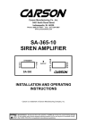
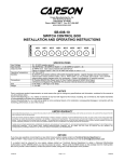
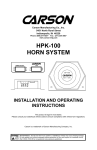
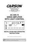
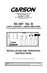
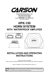
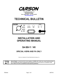
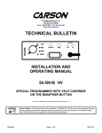
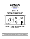
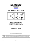
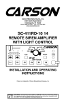
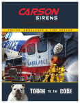
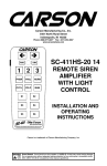
Carson Manufacturing Co., Inc.
5451 North Rural Street
Indianapolis, IN 46220
Phone: (888) 577-6877 Fax: (317) 254-2667
www.carsonsirens.com
SC-1002 / 1012 / 1022-10
SIREN AMPLIFIER W/ LIGHT CONTROL
OUTPUT
M
A
N
LT1
LT2
MECH
PHSR
WAIL
A
U
T
O
YELP
HORN
SC-1002
SC-1012
MECH
MAN
PHSR
LT1
LT2
W
A
I
L
S
T
B
Y
AUTO
YELP
REMOTE PANEL
SC-1022
LT2
LT1
HORN
PHSR
MECH
YELP
MAN
AUTO
LAMP
NEG
MAN
HORN
MECH
WAIL
YELP
PHSR
LT1
LT2
HORN
OUTPUT
POWER
HAND
CONTROL
SC-1000
INSTALLATION AND OPERATING
INSTRUCTIONS
Carson is a trademark of Carson Manufacturing Company, Inc.
Sound Hazard - Sound level from siren speaker (>120dBA @ 10 feet) may cause hearing damage.
Do not operate siren without adequate hearing protection for you and anyone in immediate vicinity.
(Ref. OSHA 1910.95 for occupational noise exposure guidelines)
Page 2 of 16
SC-1002 / 1012 / 1022-10 14 Installation Instructions
TABLE OF CONTENTS
GENERAL DESCRIPTION .................................................................................... 3
SPECIFICATIONS................................................................................................. 3
INSTALLATION ..................................................................................................... 4
SAFETY PRECAUTIONS ................................................................................. 4
UNPACKING..................................................................................................... 4
OPTION SWITCHES ........................................................................................ 5
MOUNTING....................................................................................................... 6
ELECTRICAL CONNECTIONS ........................................................................ 7
OPERATION (SC-1002 / 1012 Model) ............................................................... 11
POWER ON/OFF ............................................................................................ 11
SIREN CONTROLS ........................................................................................ 11
Man or Auto Selector Switch ..................................................................... 11
Mech - Wail - Yelp Selector Switch ........................................................... 11
Phaser Button (SC-1002) or Rocker (SC-1012) ........................................ 11
Horn Button (SC-1002) or Rocker (SC-1012)............................................ 11
Auxiliary Input Functions ........................................................................... 11
Horn Ring Cycler 2 (HRC2) ...................................................................... 11
LIGHT CONTROLS......................................................................................... 12
LT1 and LT2 Lighted Rocker Switches...................................................... 12
OPERATION (SC-1022 Model) .......................................................................... 13
POWER ON/OFF ............................................................................................ 13
SIREN CONTROLS ........................................................................................ 13
Mech, Wail, Yelp, and Phaser Pushbutton Switches................................. 13
Manual Pushbutton Switch ........................................................................ 13
Horn Pushbutton Switch ............................................................................ 13
Auxiliary Input Functions ........................................................................... 13
Horn Ring Cycler 2 (HRC2) (See page 11) ............................................ 13
LIGHT CONTROLS......................................................................................... 13
LT1 and LT2 Pushbutton Switches............................................................ 13
SERVICE ............................................................................................................. 14
PROBLEMS .................................................................................................... 14
PARTS and ACCESSORIES .......................................................................... 15
RETURNS ....................................................................................................... 16
WARRANTY .................................................................................................... 16
NOTICE
Due to continuous product improvements, we must reserve the right to change any specifications and information,
contained in this manual at any time without notice.
Carson Manufacturing Co., Inc. makes no warranty of any kind with regard to this manual, including, but not
limited to, the implied warranties of merchantability and fitness for a particular purpose.
Carson Manufacturing Co., Inc. shall not be liable for errors contained herein or for incidental or consequential
damages in connection with the furnishing, performance, or use of this manual.
See www.carsonsirens.com for latest information.
2/20/08
CP4997B
SC-1002 / 1012 / 1022-10 14 Installation Instructions
Page 3 of 16
GENERAL DESCRIPTION
The SC-1000 Series Siren Amplifier with Light Control is designed for single 100W speaker use.
The SC-1002 and SC-1012 are a console unit and remote unit respectively.
The SC-1022 is a remote hand held unit with pushbutton controls.
SC-1002 / 1012 - The primary operating modes are Mechanical, Wail, Yelp, and Standby selected by 3-position rocker switches. Momentary Horn Override, Momentary Phaser Override or
push-on/push-off Phaser operation while in the Mechanical, Wail, and Yelp modes. Manual siren
control of Mechanical, Wail, and Yelp. Lights are controlled with two rocker switches. The SC1012 may be controlled with supplied switch panel or user supplied switches.
SC-1022 - The primary operating modes are Mechanical, Wail, Yelp, Phaser, and Standby
selected by four pushbutton switches. Momentary Horn Override pushbutton and Manual siren
pushbutton for control of Mechanical, Wail, Yelp, and Phaser. Lights are controlled with two
pushbuttons as well.
On all units, an internal DIP switch provides options to change tones, disable tones, HRC2 operation, and Auxiliary input polarity. The units utilize short circuit, high voltage, and reverse polarity
protection systems for maximum service life. An output light indicates siren signal output for
diagnostics and troubleshooting.
SPECIFICATIONS
Input Voltage
Input Current
Standby Current
Siren Section
9 - 16 VDC (negative ground)
8 AMPS (@14 VDC - single 100W speaker)
< 100 ma (@ 14 VDC w/ enable lead energized)
Output Power
Siren Frequency
Tones / Cycle Rates
Cycle Rates
105 WATTS RMS MAX. (15 VDC - single 100W speaker)
700Hz - 1500Hz (Mechanical 700Hz - 1600Hz; Two-Tone and Horn = 435 & 585Hz)
Horn
Mechanical
Wail
Yelp
Phaser
Two-Tone
109 CPS
5 CPM
13 CPM
190 CPM
15 CPS
60 CPM
High Voltage
Protection
Short Circuit Current
16 - 18 VDC will cause siren output to cease, resumes at normal voltage
Operating Temp.
Controls
(SC-1002 / 1012)
-15° F to +140°F
Two 3-position rocker switches (Mechanical, Wail, Yelp, Manual, and Standby).
SC-1002 - Pushbutton switches (Horn and Phaser momentary or toggle).
SC-1012 - Momentary rocker switch (Horn and Phaser momentary or toggle).
Auxiliary input programmable for positive or negative activation.
Internal 8-position DIP switch option selector.
Six Pushbutton switches for Mechanical, Wail, Yelp, Phaser, Manual, and Horn.
Auxiliary input programmable for positive or negative activation.
Internal 8-position DIP switch option selector.
Screw down terminals for Positive and Negative Supply; Removable 6-Pos Terminal
Block (2) Speaker, Auxiliary and Enable inputs, (2) light control outputs.
SC-1012 has removable 10-Pos Terminal Block Plug for remote panel.
SC-1022 hand control has built-in cable for connection to unit.
Light Control Section
Controls
(SC-1022)
Connections
Controls
50 AMPS (supply circuit must be capable of supplying this)
Current
SC-1002 / 1012 has two lighted rocker switches.
SC-1022 has two pushbuttons.
20 AMPS per switch, 20 AMPS total
Connections
Two light control outputs (see 6-Pos Terminal Block under Siren Connections)
Size
6" Wide, 6" Deep, 2" High
Weight
SC-1002 - 3 LBS; SC-1012 / 1022 - 3-1/2 LBS.
General
CP4997B
2/20/08
Page 4 of 16
SC-1002 / 1012 / 1022-10 14 Installation Instructions
INSTALLATION
Proper installation of the unit is essential for years of safe, reliable operation. Please read all
instruction before installing the unit. Failure to follow these instructions can cause serious damage to the unit or vehicle and may void warranties.
SAFETY PRECAUTIONS
For the safety of the installer, vehicle operator, passengers and the community please observe
the following safety precautions. Failure to follow all safety precautions and instructions may
result in property damage, injury or death.
Qualifications - The installer must have a firm knowledge of basic electricity, vehicle electrical
systems and emergency equipment.
Sound Hazard - Sound level from siren speaker (>120dBA @ 10 feet) may cause hearing damage.
Do not operate siren without adequate hearing protection for you and anyone in immediate vicinity.
(Ref. OSHA 1910.95 for occupational noise exposure guidelines)
Hand Control Location - Locate the hand control for easy access by the vehicle operator. DO
NOT locate in air bag deployment area
Mounting - Mount the unit for easy access by the vehicle operator. DO NOT mount in air bag
deployment area. Assure clearances before drilling in vehicle.
Wiring - Use wiring capable of handling the current required. Make sure all connections are tight.
Route wiring to prevent wear, overheating and interference with air bag deployment. Install and
check all wiring before connection to vehicle battery.
Testing - Test all siren functions after installation to assure proper operation. Test vehicle operation to assure no damage to vehicle.
Keep These Instructions - Keep these instructions in the vehicle or other safe place for future
reference. Advise the vehicle operator of the location.
UNPACKING
Inspect contents for shipping damage. If found alert carrier immediately.
Contact supplier immediately if any items are missing.
Contents of box should include the following items:
Qty Item
Bracket, ‘U’ Dash Mount (CP3571)
1
SC-1002 SC-1012 SC-1022
X
X
X
X
X
X
1
Mounting Bracket Hardware (ED1608 Hardware Kit)
(Kit contains 2 Bolts, 2 Nuts, and 4 Lockwashers)
Connector, 6-P Terminal Block Plug (CP4956-06)
X
X
X
1
1
Console Unit (SC-1002-10 14)
Remote Amplifier (SC-1000-10 14)
X
X
X
1
Remote Panel Assembly (SC-1012-10CH)
X
1
Connector, 10-P Terminal Block Plug (CP4688-10)
X
20
Terminal, 3/16” Insulated Female Q.C. (CP4062-K2523)
X
1
Hand Control Assembly (SC-1022-10CH)
X
1
1
Velcro Strip Fastener (VELCRO)
Instruction Manual (CP4997 This Manual)
X
X
1
2/20/08
X
X
CP4997B
SC-1002 / 1012 / 1022-10 14 Installation Instructions
Page 5 of 16
OPTION SWITCHES
An internal 8-position DIP switch on the circuit board may be changed to select various options.
Accessing Option Switches - the DIP switch is located just behind the front panel of the amplifier. Use a 7/64” allen wrench to remove the 4 corner screws then remove front panel.
OUTPUT
A
U
T
O
LT1
LT2
REMOTE PANEL
OUTPUT
POWER
HAND
CONTROL
MECH
WAIL
YELP
PHSR
HORN
LT2
LT1
HORN
PHSR
MECH
YELP
MAN
AUTO
LAMP
NEG
M
A
N
SC-1000
SC-1002
Adjusting Option Switches - it is easiest to view the DIP
switch with the unit turned upside down. With the unit
upside down, the DIP Switch is located on the internal
PCB assembly board toward the left side of the unit.
Switch 1 is toward the front of the unit. Switch ‘ON’ position is toward the left side of the unit.
The default setting is shown here. Switch 1 is on.
ON
1
2
3
4
5
6
7
8
SW-1 (AUX_P) Auxiliary Input Polarity - The auxiliary input is normally activated with positive.
Turn switch off for negative activation.
SW-2 (INST_ON) Instant ON - The Enable input wiring is normally required to turn on the unit.
Turning this switch on allows the front panel switches to instantly turn on the unit.
(SC-1002 and SC-1012 only)
SW-3 (T-T) Two-Tone - Turn this switch on to replace Phaser with Two-Tone.
SW-4 (H_I) Horn Inhibit - Turn this switch on to disable Horn tone. Horn will be replaced with
Yelp.
SW-3 and 4 Tone Disable - All siren tones may be disabled except Manual, Wail and Yelp by
turning on both switches. Mechanical will be replaced with Wail. Phaser and Horn will be replaced with Yelp.
SW-5 (HRC) Horn Ring Cycler 2 (HRC2) - While the siren is in standby, the auxiliary input can
cycle through Mechanical, Wail, Yelp, and Phaser tones by repeatedly activating the auxiliary
input. Turn this switch on for HRC2 feature. See OPERATION section for further details.
SW-6 (SM) Short Manual - The Manual siren tone will normally fall and die out when released.
Turn this switch on to have Manual stop immediately.
SW-7 (MECH2) Mechanical Tone 2 - Turn this switch on for a different mechanical tone sound.
SW-8 (FALL) Mechanical Fall - Turn this switch on for a quicker mechanical tone fall time.
CP4997B
2/20/08
Page 6 of 16
SC-1002 / 1012 / 1022-10 14 Installation Instructions
MOUNTING (Main unit)
The mounting bracket supplied can be installed above
or below the unit. Mounting bolts slide into channels
on each side of the case. Lockwashers should be
used between the case and bracket as well as between the bracket and nut. Choose a mounting location convenient to the operator and away from any air
bag deployment areas. Inspect behind mounting area
for clearance. Assure adequate ventilation to prevent
overheating. Consider wire routing and access to
connections. Install mounting bracket to vehicle using
1/4" hardware (not supplied).
Lockwashers
Nut
Channel
(from rear)
Bolt
Bracket
SC-1012 Remote Panel: The remote panel of the SC-1012 is typically mounted underneath the
vehicle dashboard using mounting hardware (not supplied). Mount the panel in a location away
from the driver’s or passenger’s legs.
SC-1022 Hand Control: Choose a mounting location convenient to the operator and away from
any air bag deployment areas. Consider cable routing to amplifier. Mount the hand control with
supplied Hook and Loop tape (VELCRO). If the tape method is not preferred, the hand control
may be mounted several ways. A Holster (CP5003) to hold the Hand Control or a Hanger and
Holder to hold the Hand Control like a microphone (ED1865) are available accessories.
See PARTS and ACCESSORIES Section.
2/20/08
CP4997B
SC-1002 / 1012 / 1022-10 14 Installation Instructions
Page 7 of 16
ELECTRICAL CONNECTIONS
Electrical connections to the unit are made using terminal block plugs and screw terminals located
on the amplifier. Labels on the unit identify each terminal function. Install the plug on the unit
before wiring. If the unit needs service the plug can be easily removed without unwiring. The
power supply of the unit must be capable of delivering peak currents up to 50 amps for adequate
short circuit protection and reliable operation. The preferred source is directly at the vehicle battery. The amplifier is fused.
Attach leads by stripping 3/8”, inserting into plug and clamp by tightening screw. Make sure the
screw is tight and the wire can’t be pulled out.
Failure to adequately tighten the screw can result in improper operation or burning the
connector and wire.
Wire Size and Termination - The diagram shows the minimum wire size used for each connection, along with recommended lead color. If the wire is longer than 10 ft. use the next larger wire
size. Use only high quality crimp connectors for installation on the vehicle.
Unit Enable Input Connection (ORG lead on wiring diagram next page) - This is NOT the same
as the main power connection. The unit enable is like a power switch for the unit. When there
is positive power at this connection, the unit is powered up and ready to function. Likewise when
power is removed, the unit is not powered up and will not drain current from the battery. Connect
to a positive circuit controlled by the vehicle ignition switch, usually a terminal at the vehicle fuse
panel. The required current is low (15mA typ.).
Note: The unit may also be configured to power up without this connection on SC-1002 / 1012.
See Instant ON under OPTION SWITCHES section.
Note: This connection must be used on SC-1022.
Auxiliary Input Connection (Optional) - A momentary input typically connected to the horn ring
of the vehicle or other switch. See OPERATION section for auxiliary input functions.
The auxiliary input may be activated with positive or negative voltage. See Auxiliary Polarity
under OPTION SWITCHES section for proper activation polarity. Input current is 1 to 20 mA.
SEE WIRING DIAGRAMS NEXT PAGES
CP4997B
2/20/08
Page 8 of 16
SC-1002 / 1012 / 1022-10 14 Installation Instructions
ELECTRICAL CONNECTIONS CONTINUED (ALL MODELS)
+VDC
HORN
RING
SWITCH
+VDC
HORN
RING
SWITCH
SPLICE
Added
SPDT
Switch
MOMENTARY
FOOT
SWITCH
HORN
For Aux Input Connection
If just a splice is made to
vehicle horn circuit, the
vehicles horn will also
sound with the siren.
AUX
-
HORN
VDC
switching
example
AUX
AUX
Must set AUX_P
option switch
+VDC Switching examples
#22 AWG WHT
Load 1 and Load 2
Recommended
Wire Size
Amps
Size
5 - 10
#16
10 - 15
#14
15 - 20
#12
Load
1
AWG
see table
Load
2
Use next larger size if
longer than 10 ft.
-
Unit Enable
(like an ON/OFF switch)
Connect to positive circuit
#22 AWG (fuse panel) controlled by
ORG
ignition or other switch
AWG see table
On SC-1022
Unit enable must be connected.
On SC-1002 / 1012
Unit enable must be connected
unless option SW-2 is changed.
See page 5.
#16 AWG BLK
BAT
+
RED
#18 AWG BRN
RED (Positive Supply)
Recommended Wire Size
Load 1 + Load 2 +
8 for Amplifier
Size
Amps
#10
6-P Terminal Block Plug
(CP4956-06)
Use next larger size if
longer than 10 ft.
25A Automotive
Type Fuse
Do not remove nut
2/20/08
LT2
NEG
POS
LITE
FUSE
Plug into unit first for
terminal identification
Back of Unit
SPK
25 - 28
Plug installed
this orientation
SPK
#12
AUX
#14
15 - 25
ENA
#16
LT1
8 - 10
10 - 15
#18 AWG BRN
15A Automotive
Type Fuse
SIREN
FUSE
Do not remove nut
CP4997B
SC-1002 / 1012 / 1022-10 14 Installation Instructions
Page 9 of 16
ELECTRICAL CONNECTIONS CONTINUED (SC-1012 only)
Front of Unit
REMOTE PANEL
LT2
LT1
HORN
PHSR
MECH
YELP
MAN
AUTO
LAMP
NEG
Plug into unit first for
terminal identification
10-P Terminal Block Plug
(CP4688-10)
Plug installed
this orientation
Remote Panel wired to terminal block plug
Suggest wires be #22 AWG (not supplied)
NEG
AUTO
MAN
YELP
MECH
HORN
PHSR
LT1
LT2
LAMP
Note Top Orientation
SC-1012
MAN
MECH
PHSR
YELP
HORN
LT1
LT2
W
A
I
L
S
T
B
Y
AUTO
LT1 and LT2 Lighted Rocker Switches may control devices directly bypassing the unit.
LT1 and LT2
Lighted Rocker Switch
Circuit
LAMP
LT1 and LT2 Lighted Rocker Switches are rated 20 Amps each.
Proper fusing should be used to protect the switch and circuit.
FUSE
FOR LAMP #22 AWG
-VDC
INPUT #12 AWG *
+VDC
OUTPUT #12 AWG *
+VDC
OUT
* - See Load Wire Size chart on Page 8
CP4997B
OR
+VDC
-VDC
-VDC
OUT
2/20/08
Page 10 of 16
SC-1002 / 1012 / 1022-10 14 Installation Instructions
ELECTRICAL CONNECTIONS CONTINUED (SC-1022 only)
Front of Unit
HAND
CONTROL
Plug hand control into unit
SC-1022
MAN
HORN
MECH
WAIL
YELP
PHSR
LT1
LT2
Note: Cable may be extended with ED1753 Hand Control Cable Extension Kit.
See PARTS and ACCESSORIES Section.
Do not extend with other cables which may cause unreliable operation or damage.
2/20/08
CP4997B
SC-1002 / 1012 / 1022-10 14 Installation Instructions
Page 11 of 16
OPERATION
SC-1002 and SC-1012 Models
Sound Hazard - Sound level from siren speaker (>120dBA @ 10 feet) may cause hearing damage.
Do not operate siren without adequate hearing protection for you and anyone in immediate vicinity.
(Ref. OSHA 1910.95 for occupational noise exposure guidelines)
POWER ON/OFF
The unit is enabled (turned on) by applying positive voltage to the orange enable lead. On the
SC-1002, backlight turns on. On the SC-1012 remote amplifier, POWER light comes on.
This is normally controlled with the ignition switch on the vehicle. See INSTALLATION section.
An Instant ON feature may be selected so the unit is turned on when the front panel controls are
activated. See OPTION SWITCHES section.
SIREN CONTROLS
MAN - STBY - AUTO SELECTOR SWITCH
MECH
MAN
A 3-position rocker selector switch controls the primary operating mode
of the siren.
W
Manual - Provides manual control of Mechanical and Wail tone rise and S
A
fall or momentary Yelp depending on the position of Mech - Wail - Yelp T
I
B
switch.
L
Y
Auto - Keeps siren tone running (automatic rise and fall). Tone depends
on the position of Mech - Wail - Yelp switch.
YELP
AUTO
Standby - A silent mode that may be overridden anytime.
MECH - WAIL - YELP SELECTOR SWITCH
A 3-position rocker selector switch controls the primary siren tone.
Mech - A simulated mechanical siren tone. Tone may be changed or
disabled. See OPTION SWITCHES section.
Wail - A slower changing tone used on highways.
Yelp - A rapidly changing tone used in congested areas.
SC-1002
PHASER BUTTON (SC-1002) or ROCKER (SC-1012)
PHSR
A very rapid changing tone used at intersections and very highly congested
areas. With selector switch in Auto, this tone override is toggled on and off
by repeatedly pressing switch. With selector switch in Standby, this tone
override is momentary as long as the switch is pressed. May be optionally
replaced with Two-Tone or disabled. Two-Tone is two alternating frequencies like a European HI-LO. See OPTION SWITCHES section.
HORN
SC-1012
PHSR
HORN BUTTON (SC-1002) or ROCKER (SC-1012)
Produces a simulated Air-Horn tone while pressed. Overrides all siren
modes. Horn tone may be disabled. See OPTION SWITCHES section.
AUXILIARY INPUT FUNCTIONS
HORN
The switch or horn ring attached is intended to be momentary.
With selector switch in Standby, activating auxiliary is the same function as activating Manual.
Note that the orange enable lead must be activated for the unit to be on while in Standby.
When the selector switch is in Auto activating auxiliary is the same as pressing Horn switch.
Horn Ring Cycler 2 (HRC2) - this feature may also be added by turning on the HRC2 option.
HRC2 is only available while the unit is in Standby. Tapping the attached horn ring or other
switch, will bring the unit out of standby into Mechanical tone. Repeatedly tapping the horn ring
will cycle through Mechanical, Wail, Yelp, and Phaser tones. Tapping the horn ring twice quickly
will stop the siren tones and return the unit to standby. Pressing and holding the horn ring will
produce Horn tone until released. Then the siren will return to its previous siren tone or standby.
Selector
Mech - Wail - Yelp
Phaser
Horn
Auxiliary Input
Position
Position
Switch
Switch
(Horn Ring)
Standby
Silent
Mom. Phsr
Horn Man. Mech., Man., or Yelp or HRC2
Manual Man. Mech., Man., or Yelp Phsr Toggle Horn
Horn
Auto
Mechanical, Wail, or Yelp Phsr Toggle Horn
Horn
CP4997B
2/20/08
Page 12 of 16
SC-1002 / 1012 / 1022-10 14 Installation Instructions
OPERATION (SC-1002 and SC-1012 Models continued)
LIGHT CONTROLS
LT1 and LT2 LIGHTED ROCKER SWITCHES
When turned on the rocker switch will light up and activate the
corresponding light output.
2/20/08
LT1
LT2
CP4997B
SC-1002 / 1012 / 1022-10 14 Installation Instructions
Page 13 of 16
OPERATION (continued)
SC-1022 Model
Sound Hazard - Sound level from siren speaker (>120dBA @ 10 feet) may cause hearing damage.
Do not operate siren without adequate hearing protection for you and anyone in immediate vicinity.
(Ref. OSHA 1910.95 for occupational noise exposure guidelines)
POWER ON/OFF
The unit is enabled (turned on) by applying positive voltage to the orange enable lead. The
POWER light on remote amplifier should come on. The hand control should also be backlit.
This is normally controlled with the ignition switch on the vehicle. See INSTALLATION section.
SIREN CONTROLS
MECH, WAIL, YELP, AND PHSR PUSHBUTTON SWITCHES
Four pushbutton switches control the primary operating mode of the siren.
The primary operating modes are:
Standby - A silent mode that may be overridden at any time.
Mech - A simulated mechanical siren tone. Tone may be changed or disabled. See
OPTION SWITCHES section.
Wail - A slower changing tone used on highways.
Yelp - A rapidly changing tone used in congested areas.
Phaser - A very rapid changing tone used at intersections and very highly congested
areas. May be optionally replaced with Two-Tone or disabled. Two-Tone is two
alternating frequencies like a European HI-LO. See OPTION SWITCHES section.
SC-1022
MAN
HORN
MECH
WAIL
YELP
PHSR
LT1
LT2
Momentarily press button to activate (lit red). Momentarily press button again to de-activate. Also
while a particular mode is activated, switch to a different mode by pressing one of the other three
buttons. The unit is in Standby when NONE of the four buttons are activated (NOT lit red). For
example starting with all four buttons off (Standby) press the Wail button to turn on Wail. Now
press the Yelp button to change to Yelp. Press the Yelp button again to turn off sound (Standby).
MAN PUSHBUTTON SWITCH
Provides manual control of siren tone depending on the primary operating mode selected.
While in Standby, the Manual button controls the Mechanical tone. Rising to peak while pressed
then falling until die out when released. While in Mech, Wail, Yelp, or Phaser mode, pressing the
Manual button causes tone to rise and peak then resume when released.
HORN PUSHBUTTON SWITCH
Produces a simulated Air-Horn tone while pressed. Overrides all siren modes. Horn tone may be
disabled. See OPTION SWITCHES section.
AUXILIARY INPUT FUNCTIONS
The switch or horn ring attached is intended to be momentary. While in Standby, activating auxiliary is same function as activating Manual button. While in Mech, Wail, Yelp, or Phaser mode,
activating auxiliary is same function as Horn button.
Horn Ring Cycler 2 (HRC2) - this feature may also be added. See description on Page 11.
Primary Mode
and Tone
Standby (Silent)
Mechanical
Wail
Yelp
Phaser
MAN
Button
Man. Mech
Man. Mech. Rise
Manual Rise
Manual Rise
Manual Rise
HORN
Button
Horn
Horn
Horn
Horn
Horn
Auxiliary Input
(Horn Ring)
Man. Mech. or HRC2
Horn
Horn
Horn
Horn
LIGHT CONTROLS
LT1 and LT2 PUSHBUTTON SWITCHES
Momentarily push button to activate (will light red) corresponding light output.
Momentarily push button again to de-activate corresponding light output.
CP4997B
2/20/08
Page 14 of 16
SC-1002 / 1012 / 1022-10 14 Installation Instructions
SERVICE
This unit is designed to provide years of reliable service under even the worst conditions. Many
times there may appear to be a problem with the unit when the true problem is in the speaker,
controlled devices, or improper installation. The following chart shows typical symptoms and
possible causes.
A blown siren fuse doesn't necessarily mean that the unit is bad. If a speaker or speaker lead is
shorted the fuse will blow before the unit is damaged. Disconnect the SPKR leads and replace
the fuse. If the OUTPUT light comes on with siren power enabled and Wail mode selected it is
OK. Check the speaker or leads for possible shorting.
PROBLEMS
Symptom
Possible Cause
No power or siren No power to enable input (org wire)
output
Bad speaker
Connector(s) loose
Rear panel fuse blown
Loose connection at power source
No siren tones
Bad Speaker
High Voltage Protection
Distorted siren
Speaker assembly loose
sound
Intermittent Aux Input connection
Low vehicle voltage
Intermittent siren High Voltage Protection
tone
Connector loose
Bad power connection
Circuit breaker in supply connection
Horn function
Horn or Manual switch stuck
stuck on or
Aux Input improperly connected
Manual stuck on Aux Input Polarity Option set wrong
Wrong siren tone Two-Tone option installed
Tones disabled.
Some siren tones Tone disabled
not working
Light switches not Loose output connections
working
Rear panel fuse blown
Check
Does backlighting or POWER light come on?
Is the OUTPUT light on face coming on in Wail?
Do you hear a "pop" when turned on?
Is an external fuse or circuit breaker used?
Are the negative leads connected to a good ground?
Is the OUTPUT light on face coming on in Wail?
Input voltage must be less than highest rated voltage.
Is the speaker bell or tip loose?
Is the Aux Input used and wired properly?
Input voltage must be greater than lowest rated voltage.
Is the vehicle voltage regulator working properly?
Is the connector tight on the back of the unit?
Is there a loose connection on a power lead?
Is a circuit breaker used with at least a 50A rating?
Does the horn or manual switch return when released?
Is the Aux Input used and wired properly?
Is the AUX_P option properly configured?
Is the T-T option selected?
Check option switch settings.
Check option switch settings.
Do the Light Control switch indicators light?
Is the corresponding fuse blown?
See www.carsonsirens.com for additional information
or contact our Service Department at:
E-mail [email protected] or Phone (888) 577-6877.
2/20/08
CP4997B
SC-1002 / 1012 / 1022-10 14 Installation Instructions
Page 15 of 16
PARTS and ACCESSORIES
The following parts and accessories are available from Carson Manufacturing Company, Inc.:
Part
CP4990-150
CP4990-250
CP4748-2
CP4751-2
CP4995-2
CP4993
CP4998
Description
Fuse, 15 Amp Mini Automotive (Siren)
Fuse, 25 Amp Mini Automotive (Lite)
Switch, Red Rocker ON - OFF - ON (Mech - Wail - Yelp) (SC-1002 / 1012)
Switch, Momentary Red Rocker Switch, (ON) - OFF - (ON) (Phsr - Horn) (SC-1012)
Switch, Red Rocker (ON) - OFF - ON (Man - Standby - Auto) (SC-1002 / 1012)
Switch, Lighted Rocker for Light Control (SC-1002 / 1012)
Transistor, output (replace in pairs, 2 required)
Accessory
CP3571 *
ED1608 *
CP4956-06 *
Description
* - standard accessory supplied with unit
Bracket, ‘U’ dash mount (Amplifier)
Mounting Hardware Kit (2 bolts, 2 nuts, 4 lockwashers)
Connector, 6-pin Terminal Block Plug
CP4688-10 *
CP4062-K2523 *
SC-1000-10 14 *
SC-1012-10CH *
SC-1022-10CH *
Connector, 10-pin Terminal Block Plug (SC-1012)
Terminal, 3/16" insulated female Q.C.- AMP#2-520194-2 or equivalent (SC-1012)
SC-1012 / 1022 Remote Amplifier
SC-1012 Remote Panel Assembly (includes rocker switches)
SC-1022 Hand Control Assembly
SC-1022 Hand Control Holster
SC-1022 Hanger and Holder Kit
Cable, Hand Control Extension 15FT Kit (includes CP4652 shielded cable & CP4141 modular coupler) (SC-1022)
CP5003
ED1865
ED1753
VELCRO *
CP4997 *
Velcro Strip Fastener (SC-1022)
Instruction Manual
See www.carsonsirens.com for additional information
or contact our Service Department at:
E-mail [email protected] or Phone (888) 577-6877.
CP4997B
2/20/08
Page 16 of 16
SC-1002 / 1012 / 1022-10 14 Installation Instructions
RETURNS
If you have any questions concerning this or any other Carson product, please contact our Service Department at (888) 577-6877. Many issues can be handled over the phone. We can also
be reached via e-mail at [email protected]
If a product must be returned for any reason, please contact our Technical Service Department to
obtain a Returned Merchandise Authorization number (RMA#) before you ship the product to
Carson. Please write the RMA# clearly on the package near the mailing label. Be sure to provide
a return address, contact and phone number, along with a brief description of the problem.
LIMITED WARRANTY
Carson Manufacturing Company, Inc. warrants this new product to be free from defects in
material and workmanship, under normal use and service, for a period of five (5) years from
the date of delivery to the first user-purchaser.
During this warranty period the obligation of Carson Manufacturing is limited to repairing or
replacing, as Carson Manufacturing may elect, any part or parts of such product which after
examination by Carson Manufacturing is determined to be defective in material and/or workmanship.
This warranty does not cover labor charges for removal or re-installation of the product.
Fuses and lamps are not covered under this warranty.
This warranty does not extend to any unit that has been subjected to abuse, misuse, improper installation or which has not been adequately maintained, nor to units which have
problems related to service or modification at any facility other than Carson Mfg.
THERE ARE NO OTHER WARRANTIES, EXPRESSED OR IMPLIED, INCLUDING BUT
NOT LIMITED TO, ANY IMPLIED WARRANTIES OF MERCHANTABILITY OR FITNESS
FOR A PARTICULAR PURPOSE. IN NO EVENT SHALL CARSON MANUFACTURING
COMPANY, INC. BE LIABLE FOR ANY LOSS OF PROFITS OR ANY INDIRECT OR CONSEQUENTIAL DAMAGES ARISING OUT OF ANY SUCH DEFECT IN MATERIALS OR
WORKMANSHIP.
2/20/08
CP4997B