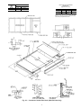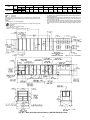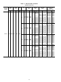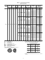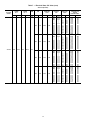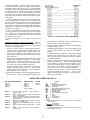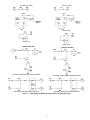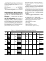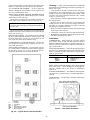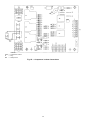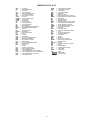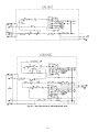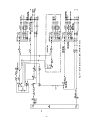
1
48DJ,DK,NP034-074
50DJ,DK,DW,DY,NB,NP034-074
Single Package Heating and Cooling Units
Installation, Start-Up and
Service Instructions
CONTENTS
Page
GENERAL . . . . . . . . . . . . . . . . . . . . . . . . . . . . . . . . . . . 2
SAFETY CONSIDERATIONS . . . . . . . . . . . . . . . . . . . 2
INSTALLATION . . . . . . . . . . . . . . . . . . . . . . . . . . . . . 2-37
Rigging and Unit Placement . . . . . . . . . . . . . . . . . . 2
Roof Curb . . . . . . . . . . . . . . . . . . . . . . . . . . . . . . . . . . . 2
Roof Mount . . . . . . . . . . . . . . . . . . . . . . . . . . . . . . . . . . 2
Slab Mount . . . . . . . . . . . . . . . . . . . . . . . . . . . . . . . . . . 2
Positioning . . . . . . . . . . . . . . . . . . . . . . . . . . . . . . . . . . 3
Field-Fabricated Ductwork . . . . . . . . . . . . . . . . . . . . 6
Condensate Drains . . . . . . . . . . . . . . . . . . . . . . . . . . 10
Install Outdoor Hoods . . . . . . . . . . . . . . . . . . . . . . . 10
• UNIT SIZES 034 AND 044
• UNIT SIZES 054-074
Outdoor-Air Inlet Adjustments . . . . . . . . . . . . . . . 10
• MANUAL OUTDOOR-AIR DAMPER
• ECONOMIZER SETTINGS
Field Wire Routing . . . . . . . . . . . . . . . . . . . . . . . . . . 17
• UNIT SIZES 034 AND 044
• UNIT SIZES 054-074
Field Electrical Connections . . . . . . . . . . . . . . . . . 17
• POWER WIRING
• CONTROL WIRING
Gas Piping (48 Series Units Only) . . . . . . . . . . . . 36
Installing Flue/Inlet Hoods (48 Series Units
Only) . . . . . . . . . . . . . . . . . . . . . . . . . . . . . . . . . . . . . . 36
• UNIT SIZES 034 AND 044
• UNIT SIZES 054-074
PRE-START-UP . . . . . . . . . . . . . . . . . . . . . . . . . . . . 38-41
Unit Preparation . . . . . . . . . . . . . . . . . . . . . . . . . . . . 38
Compressor Mounting . . . . . . . . . . . . . . . . . . . . . . . 38
Evaporator-Fan Shipping Brackets . . . . . . . . . . . 38
• UNIT SIZES 034 AND 044
• UNIT SIZES 054-074
Internal Wiring . . . . . . . . . . . . . . . . . . . . . . . . . . . . . . 38
Refrigerant Service Valves . . . . . . . . . . . . . . . . . . . 38
Crankcase Heaters . . . . . . . . . . . . . . . . . . . . . . . . . . 38
Compressor Oil . . . . . . . . . . . . . . . . . . . . . . . . . . . . . 38
Gas Manifold Pressure (48 Series
Units Only) . . . . . . . . . . . . . . . . . . . . . . . . . . . . . . . . 39
Unit Voltage . . . . . . . . . . . . . . . . . . . . . . . . . . . . . . . . 39
Leak Test and Dehydration . . . . . . . . . . . . . . . . . . 39
Evaporator-Fan Belts, Pulleys, and Sheaves . . 39
Condenser Fans and Motors . . . . . . . . . . . . . . . . . 40
Return-Air Filters . . . . . . . . . . . . . . . . . . . . . . . . . . . 40
Economizer Inlet Screens . . . . . . . . . . . . . . . . . . . 40
Economizer Dampers . . . . . . . . . . . . . . . . . . . . . . . 40
25% Outdoor-Air Damper . . . . . . . . . . . . . . . . . . . . 40
Initial Check . . . . . . . . . . . . . . . . . . . . . . . . . . . . . . . . 41
START-UP . . . . . . . . . . . . . . . . . . . . . . . . . . . . . . . . . 41,42
General . . . . . . . . . . . . . . . . . . . . . . . . . . . . . . . . . . . . . 41
Operating Sequences . . . . . . . . . . . . . . . . . . . . . . . 41
• COOLING, UNITS WITHOUT ECONOMIZER
• HEATING, UNITS WITHOUT ECONOMIZER
Page
COOLING, UNITS WITH ECONOMIZER
HEATING, UNITS WITH ECONOMIZER
VENTILATION AIR CIRCULATION (Continuous Fan)
AUTOMATIC CHANGEOVER USING AUTOMATIC
CHANGEOVER THERMOSTAT
Head Pressure Control . . . . . . . . . . . . . . . . . . . . . . 42
SERVICE . . . . . . . . . . . . . . . . . . . . . . . . . . . . . . . . . . 42-53
Service Access . . . . . . . . . . . . . . . . . . . . . . . . . . . . . 42
• COMPRESSORS
• LIQUID SERVICE VALVES, FILTER DRIERS, AND
SIGHT GLASSES
• EVAPORATOR-FAN MOTORS, PULLEYS, AND
BELTS
• POWER EXHAUST MOTORS, PULLEYS, AND
BELTS
• UNIT CONTROL BOX
• GAS HEAT SECTION (48 Series Units Only)
• MAIN AND PILOT BURNERS (48 Series Units Only)
• FLUE GAS PASSAGEWAYS (48 Series Units Only)
• COMBUSTION AIR BLOWER (48 Series Units Only)
• ECONOMIZER DAMPER MOTOR
• ELECTRIC HEATER CONTROL BOX (50 Series
Units Only)
• HEATER BOX (50 Series Units Only)
• 25% OUTDOOR-AIR DAMPER
• MODULATING POWER EXHAUST DAMPER
MOTOR
• RETURN-AIR FILTERS
• CONDENSER FANS AND FAN MOTORS
• INLET GUIDE VANE MOTOR
Cleaning . . . . . . . . . . . . . . . . . . . . . . . . . . . . . . . . . . . . 45
Lubrication . . . . . . . . . . . . . . . . . . . . . . . . . . . . . . . . . 45
• COMPRESSORS
• FAN SHAFT BEARINGS
• INLET GUIDE VANE BEARINGS (Units With
Optional Inlet Guide Vanes)
• FAN MOTOR BEARINGS
• DOOR HINGES
Adjustments . . . . . . . . . . . . . . . . . . . . . . . . . . . . . . . . 46
• EVAPORATOR FAN AND POWER EXHAUST
MOTOR PLATE
• MODULATING POWER EXHAUST DIFFERENTIAL
PRESSURE SWITCH
• INLET GUIDE VANE DIFFERENTIAL PRESSURE
SWITCH (Units With Optional Inlet Guide Vanes and
Static Pressure Control)
• BELT INSTALLATION AND TENSIONING
• PULLEY ALIGNMENT
• INSTALLING ALTERNATE MOTOR PULLEY
(Evaporator Fan Only)
• CONDENSER FAN ADJUSTMENT
• 25% OUTDOOR-AIR DAMPER
• REFRIGERANT CHARGE
• PILOT LIGHT OFF (48 Series Units Only)
•
•
•
•
Manufacturer reserves the right to discontinue, or change at any time, specifications or designs without notice and without incurring obligations.
Book 1 1
PC 111
Catalog No. 564-818
Printed in U.S.A.
Form 48/50D,N-9SI
Pg 1
3-96
Replaces: 48DJ,DK-3SI;
48/50NB,NP-1SI; 50DJ,DK-9SI
Tab 1a 1b
CONTENTS (cont)
Before performing service or maintenance operations on
unit, turn off main power switch to unit. Electrical shock
could cause personal injury.
• AUTOMATIC PILOT ADJUSTMENT (48 Series
Units Only)
• GAS VALVE ADJUSTMENT (48 Series Units Only)
• MAIN BURNER ADJUSTMENT (48 Series
Units Only)
Main Burner Removal (48 Series Units Only) . . 50
Switch Adjustment . . . . . . . . . . . . . . . . . . . . . . . . . 50
Refrigerant Feed Components . . . . . . . . . . . . . . . 50
Thermostatic Expansion Valve (TXV) . . . . . . . . . 50
Moisture/Liquid Indicator . . . . . . . . . . . . . . . . . . . . 51
Filter Drier . . . . . . . . . . . . . . . . . . . . . . . . . . . . . . . . . . 51
Liquid Line Service Valve . . . . . . . . . . . . . . . . . . . . 51
Compressor Discharge Service Valve . . . . . . . . 51
Compressor Suction Service Valve . . . . . . . . . . . 51
Protective Devices . . . . . . . . . . . . . . . . . . . . . . . . . . 51
• COMPRESSOR PROTECTION
• EVAPORATOR-FAN MOTOR PROTECTION
• CONDENSER-FAN MOTOR PROTECTION
• HIGH- AND LOW-PRESSURE SWITCHES
Relief Devices . . . . . . . . . . . . . . . . . . . . . . . . . . . . . . 51
Control Circuit, 115 V . . . . . . . . . . . . . . . . . . . . . . . 52
Control Circuit, 24 v . . . . . . . . . . . . . . . . . . . . . . . . . 52
Electric Heat (50 Series Units Only) . . . . . . . . . . 52
• OVERCURRENT
• OVERTEMPERATURE
Gas Heat (48 Series Units Only) . . . . . . . . . . . . . . 52
• LIMIT SWITCHES
• ROLLOUT SWITCH
TROUBLESHOOTING . . . . . . . . . . . . . . . . . . . . . . 52-69
Economizer . . . . . . . . . . . . . . . . . . . . . . . . . . . . . . . . . 52
• ECONOMIZER MOTOR CHECKOUT
• ECONOMIZER CONTROL BOARD CHECKOUT
Unit Control Board Checkout . . . . . . . . . . . . . . . . 53
• BASIC CHECK
• DETAILED CHECK
START-UP CHECKLIST . . . . . . . . . . . . . . . . . . . . . CL-1
Do not try to light any appliance. Do not touch any electrical switch; do not use any phone in your building.
Immediately call your gas supplier from a neighbor’s
phone. Follow the gas supplier’s instructions. If you cannot reach your gas supplier, call the fire department.
Do not store or use gasoline or other flammable vapors
and liquids in the vicinity of this or any other appliance.
Improper installation, adjustment, alteration, service, or
maintenance can cause injury or property damage. Refer to this manual. For assistance or additional information, consult a qualified installer, service agency, or
the gas supplier.
Disconnect gas piping from 48 Series units when leak
testing at pressures greater than 0.5 psig. Pressures greater
than 0.5 psig will cause gas valve damage resulting in
a hazardous condition. If gas valve is subjected to pressure greater than 0.5 psig, it must be replaced. When
pressure testing field-supplied gas piping at pressures of
0.5 psig or less, the unit connected to such piping must
be isolated by manually closing the gas valve.
INSTALLATION
Rigging and Unit Placement — Inspect unit for transportation damage. File claim with transportation agency. Do
not drop unit; keep upright. Use spreader bars over unit to
prevent sling or cable damage. Sheets of plywood placed along
the condenser coils will provide additional protection. All
lifting lugs MUST be used when lifting unit. Level by using
unit frame as a reference. See Fig. 1 for information. Unit
and accessory weights are shown in Tables 1A, 1B, and 2.
Weight distribution and center of gravity can be found in
Fig. 2.
GENERAL
This installation instruction contains base unit installation, start-up, and service instructions only. For complete information on PIC (Product Integrated Controls) and variableair volume (VAV) controls and troubleshooting, refer to
appropriate Controls and Troubleshooting literature also enclosed in this literature packet.
Roof Curb — Assemble and install as described in in-
SAFETY CONSIDERATIONS
structions shipped with the accessory. Accessory roof curb
and information required to field fabricate a roof curb is shown
in Fig. 3A-3C. Install insulation, cant strips, roofing and counter
flashing as required. For unit condensate drains to function
properly, curb must be level or within tolerances shown in
Fig. 3A-3C.
Installation and servicing of air-conditioning equipment
can be hazardous due to system pressure and electrical components. Only trained and qualified service personnel should
install, repair, or service air-conditioning equipment.
Untrained personnel can perform basic maintenance functions of cleaning coils and filters and replacing filters. All
other operations should be performed by trained service personnel. When working on air-conditioning equipment, observe precautions in the literature, tags and labels attached
to the unit, and other safety precautions that may apply.
Follow all safety codes, including ANSI (American National Standards Institute) Z223.1. Wear safety glasses and
work gloves. Use quenching cloth for unbrazing operations.
Have fire extinguisher available for all brazing operations.
Roof Mount — Check building codes for weight distribution requirements. Unit weight is shown in Tables 1A and
1B. Unit may be mounted on class A, B, or C roofing
material.
Slab Mount — Provide a level concrete slab that extends beyond unit cabinet at least 6 inches. Make a slab 8 in.
thick with 4 in. above grade. Use gravel apron in front of
condenser coil air inlet to prevent grass and foliage from obstructing airflow.
2
NOTES:
1. Sizes 034,044: Rig with 4 cables and spread with two 95 in. (2413 mm) and
2 8A 1 A8 long spreader bars.
Sizes 054-074: Rig with 4 cables and spread with four 95 in. (2413 mm) and
2 8A 1 B 1 A8 long spreader bars.
2. Center of gravity includes economizer.
1. All panels must be in place when rigging.
2. Unit is not designed for handling by forklift truck.
RIGGING WEIGHTS AND DIMENSIONS
UNIT
48DJD,DKD,NPD034
48DJE,NPE034
48DJD,DKD,NPD044
48DJE,NPE044
48DJD,DKD,NPD054
48DJE,NPE054
48DJD,DKD,NPD064
48DJE,NPE064
48DJD,DKD,NPD074
48DJE,NPE074
50DJ,DK,NP034
50DW,DY,NB034
50DJ,DK,NP044
50DW,DY,NB044
50DJ,DK,NP054
50DW,DY,NB054
50DJ,DK,NP064
50DW,DY,NB064
50DJ,DK,NP074
50DW,DY,NB074
*Includes optional economizer.
UNIT WEIGHT*
Lb
Kg
5941
2694.8
6070
2753.4
6841
3103.1
6970
3161.6
9230
4186.7
9350
4241.2
9530
4322.8
9650
4377.2
9950
4513.3
10,080
4572.3
5700
2585.5
6270
2844.1
6350
2880.4
6920
3138.9
8230
3733.1
8780
3982.6
8530
3869.2
9080
4119.7
8960
4064.3
9500
4309.2
A
B
in.
mm
in.
109.4
110.4
127.6
128.6
mm
2780
2804
3240
3267
86.0
2185
92.6
2353
121.5
3086
126.8
3221
134.7
3421
134.7
3421
84.8
76.4
92.6
86.0
120.8
109.0
120.9
120.8
131.7
109.0
2153
1940
2353
2185
3066
2769
3071
3066
3345
2769
120.8
102.5
126.6
108.4
126.8
109.0
120.9
126.8
137.6
109.0
3067
2604
3216
2753
3221
2769
3071
3221
3495
2769
Fig. 1 — Rigging Label
Do not install unit in an indoor location. Do not locate air
inlets near exhaust vents or other sources of contaminated
air.
On units equipped with or power exhaust option, high velocity air is exhausted out the hoods. Unit should be positioned with at least 10 ft clearance between the exhaust hoods
and any obstruction. Although unit is weatherproof, guard
against water from higher level runoff and overhangs.
If roof curb is not used, support unit with steel beams along
its entire length and then support steel as required. As a minimum, unit must be supported across its width at each lifting
lug location.
Positioning — Provide clearance around and above unit
for airflow, safety, and service access. Do not restrict top (area
above condenser fans) in any way. Allow at least 6 ft on all
sides for rated performance, code compliance, and service.
3
Table 1A — Physical Data; 034, 044 Units
BASE UNIT*
NOMINAL CAPACITY (tons)
OPERATING WEIGHT (lb)
Base Unit
48 Series, Low Heat
48 Series, High Heat
50 Series, Horizontal Discharge
50 Series, Vertical Discharge
With Economizer
48 Series, Low Heat
48 Series, High Heat
50 Series, Horizontal Discharge
50 Series, Vertical Discharge
COMPRESSORS
Quantity...Type
Capacity Steps (%)
Number of Refrigerant Circuits
REFRIGERANT
Operating Charge (lb), Sys 1/Sys 2
Without Hot Gas Bypass
With Hot Gas Bypass
CONDENSER COILS
Quantity
Rows...Fins/in.
Aluminum
Copper (Optional)
Total Face Area (sq ft)
EVAPORATOR COILS
Quantity
Rows...Fins/in.
Total Face Area (sq ft)
Refrigerant Feed Device...No. per Circuit
HEATING SECTION (48 Series Units Only)
Number of Heat Exchangers
Input (MBtuh)
Output (MBtuh)
Temperature Rise Range (F)
Efficiency (%)
Burner Orifice Diameter
Quantity (in. ...drill no.)
Pilot Orifice Diameter
Quantity (in. ...drill no.)
Firing Stages
Number of Gas Valves
CONDENSER FANS
Quantity...Diameter (in.)
Nominal Cfm
Motor Hp...Rpm
EVAPORATOR FAN
Nominal Cfm
Maximum Allowable Cfm
Maximum Allowable Rpm
Shaft Diameter at Pulley (in.)
EVAPORATOR-FAN MOTOR AND DRIVE
Motor Hp
Motor Frame Size
Efficiency at Full Load (%)
Standard Efficiency
High Efficiency†
Fan Pulley Pitch Diameter (in.)
Motor Pulley Pitch Diameter (in.)
Resulting Fan Rpm
Belts Quantity...Model No.
48 Series and 50 Series, Horizontal Discharge
50 Series, Vertical Discharge
Center Distance Range (in.)
48 Series and 50 Series, Horizontal Discharge
50 Series, Vertical Discharge
OPTIONAL POWER EXHAUST
Quantity...Motor Hp
Motor Frame Size
Efficiency at Full Load (%)
Fan Pulley Pitch Diameter (in.)
Motor Pulley Pitch Diameter (in.)
Shaft Diameter at Pulley (in.)
Resulting Fan Rpm
Maximum Allowable Rpm
Belts Quantity...No.
FILTERS
Standard Efficiency Throwaway (Standard)
Quantity...Size (in.)
Medium Efficiency (30%) Pleated (Optional)
Quantity...Size (in.)
High Efficiency (90%) Bag Filters with Prefilters (Optional)
Quantity...Size (in.)
034
30
044
40
5641
5770
5970
5400
6541
6670
6620
6050
5941
6070
6270
5700
6841
6970
6920
6350
Semi-Hermetic
2...06D
17, 33, 50, 66, 83, 100
2
2...06E
25, 50, 75, 100
2
29.0/29.0
31.0/29.0
40.0/40.0
42.0/40.0
⁄ -in. Tube Diameter
38
2
2
3...15.0
3...13.7
37.5
3...15.0
3...13.7
50.0
⁄ -in. Tube Diameter
12
1
3...15.0
32.1
TXV...1
2
3...15.0
45.5
TXV...2
Low Heat
6
264
211
0-30
79
High Heat
12
529
423
15-45
79
Low Heat
6
264
211
0-30
79
High Heat
12
529
423
15-45
79
6 (.1285...30)
12 (.1285...30)
6 (.1285...30)
12 (.1285...30)
1 (.076...48)
2
1
2 (.076...48)
1 (.076...48)
2
2
2
1
Propeller Type
2...30
18,600
1.0...1140
2 (.076...48)
2
2
3...30
26,000
1.0...1140
Centrifugal 25 x 25 in.
10,500
15,000
900
111⁄16
14,000
20,000
900
111⁄16
(Any motor available on any unit)
10.0
15.0
215T
254T
7.5
213T
20.0
256T
82.9
—
13.7
34.4
405
85.6
89.5
13.7
4.3
510
84.5
90.0
13.7
4.9
580
87.5
91.0
13.7
5.5
660
2...BX60
2...BX60
2...5VX630
2...5VX630
2...5VX630
2...5VX630
2...5VX630
2...5VX630
17.74...14.30
17.74...14.30
17.63...14.01
17.63...14.01
19.86...15.87
19.86...15.87
19.04...15.00
19.04...15.00
Centrifugal, 15 x 15 in. (Any motor available on any unit)
2...3.0
2...5.0
2...7.5
56HZ
184T
213T
81.0
84.0
82.9
6.9
6.9
6.9
3.35
4.12
5.0
13⁄16
13⁄16
13⁄16
843
1040
1264
1300
1300
1300
2...3VX670
2...3VX670
2...3VX710
12...20
4...16
12...20
4...16
6...20
6...20
TXV — Thermostatic Expansion Valve
*Data is for all 48 and 50 Series units of the size listed unless otherwise specified.
†Not available on 575-v units.
4
x
x
x
x
x
x
25
20
25
20
24
20
x
x
x
x
x
x
2
2
2
2
22
22
12...20
4...16
12...20
4...16
6...20
6...20
x
x
x
x
x
x
25
20
25
20
24
20
x
x
x
x
x
x
2
2
2
2
22
22
Table 1B — Physical Data; 054-074 Units
BASE UNIT*
NOMINAL CAPACITY (tons)
OPERATING WEIGHT (lb)
Base Unit
48 Series, Low Heat
48 Series, High Heat
50 Series, Horizontal Discharge
50 Series, Vertical Discharge
With Economizer
48 Series, Low Heat
48 Series, High Heat
50 Series, Horizontal Discharge
50 Series, Vertical Discharge
COMPRESSORS
Quantity...Type
Capacity Steps (%)
Number of Refrigerant Circuits
REFRIGERANT
Operating Charge (lb), Sys 1/Sys 2
Without Hot Gas Bypass
With Hot Gas Bypass
CONDENSER COILS
Quantity
Rows...Fins/in.
Aluminum
Copper (Optional)
Total Face Area (sq ft)
EVAPORATOR COILS
Quantity
Rows...Fins/in.
Total Face Area (sq ft)
Refrigerant Feed Device...
No. per Circuit
HEATING SECTION (48 Series Units Only)
Number of Heat Exchangers
Input (MBtuh)
Output (MBtuh)
Temperature Rise Range (F)
Efficiency (%)
Burner Orifice Diameter
Quantity (in. ...drill no.)
Pilot Orifice Diameter
Quantity (in. ...drill no.)
Firing Stages
Number of Gas Valves
CONDENSER FANS
Quantity...Diameter (in.)
Nominal Cfm
Motor Hp...Rpm
EVAPORATOR FAN
Nominal Cfm
Maximum Allowable Cfm
Maximum Allowable Rpm
Shaft Diameter at Pulley (in.)
EVAPORATOR-FAN MOTOR AND DRIVE
Motor Hp
Motor Frame Size
Efficiency at Full Load (%)
Standard Efficiency
High Efficiency†
Fan Pulley Pitch Diameter (in.)
Motor Pulley Pitch Diameter (in.)
Resulting Fan Rpm
Belts Quantity...Model No.
48 Series and 50 Series, Horizontal Discharge
50 Series, Vertical Discharge
Center Distance Range (in.)
48 Series and 50 Series, Horizontal Discharge
50 Series, Vertical Discharge
OPTIONAL POWER EXHAUST
Quantity...Motor Hp
Motor Frame Size
Efficiency at Full Load (%)
Fan Pulley Pitch Diameter (in.)
Motor Pulley Pitch Diameter (in.)
Shaft Diameter at Pulley (in.)
Resulting Fan Rpm
Maximum Allowable Rpm
FILTERS
Standard Efficiency
Throwaway (Standard)
Quantity...Size (in.)
Medium Efficiency (30%) Pleated (Optional)
Quantity...Size (in.)
High Efficiency (90%) Bag Filters
with Prefilters (Optional)
Quantity...Size (in.)
054
50
064
60
074
75
8700
8820
8250
7700
9000
9120
8550
8000
9420
9550
8970
8430
9230
9350
8780
8230
9530
9650
9080
8530
Semi-Hermetic
2...06E
17, 33, 50, 66, 83, 100
2
9950
10,080
9500
8960
2...06E
20, 40, 60, 80, 100
2
59.0/44.5
62.0/44.5
4
2...17.0, 3...17.0
2...15.7, 3...15.7
72.4
2
3...17.0
61.5
TXV...2
2...06E
14, 28, 43, 71, 85, 100
2
61.0/61.0
64.0/61.0
3⁄8-in. Tube Diameter
4
70.5/64.5
73.5/64.5
3...17.0
3...15.7
72.4
1⁄2-in. Tube Diameter
2
4...17.0
61.5
TXV...2
3...17.0
3...15.7
108.4
4
2
4...17.0
61.5
TXV..2
Low Heat
12
540
432
5-35
80
High Heat
18
810
648
15-45
80
Low Heat
12
540
432
5-35
80
High Heat
18
810
648
15-45
80
Low Heat
12
540
432
5-35
80
High Heat
18
810
648
15-45
80
12 (.1285...30)
18 (.1285...30)
12 (.1285...30)
18 (.1285...30)
12 (.1285...30)
18 (.1285...30)
2 (.076...48)
2
2
3 (.076...48)
2
3
15.0
254T
2 (.076...48)
3 (.076...48)
2 (.076...48)
3 (.076...48)
2
2
2
2
2
3
2
3
Propeller Type
4...30
5...30
40,000
50,000
1.0...1140
1.0...1140
Centrifugal 30 x 27 in.
21,000
24,500
30,000
30,000
750
750
111⁄16
111⁄16
(Any motor available on any unit)
20.0
25.0
30.0
256T
284T
286T
84.5
90.0
13.7
4.5
555
87.5
91.0
13.7
5.1
625
87.1
91.7
13.7
5.5
660
88.3
92.4
15.5
5.9
700
2...5VX1120
2...5VX1230
2...5VX1150
2...5VX1230
2...5VX1150
2...5VX1230
2...5VX1180
2...5VX1230
4...30
40,000
1.0...1140
17,500
25,000
750
111⁄16
48.25...44.00
44.25...39.75
48.25...44.00
48.50...44.25
44.25...39.75
44.00...40.00
Centrifugal, 18 x 15 in. (Any motor available on any unit)
2...7.5
213T
82.9
10.6
5.0
17⁄16
820
925
2...5.0
184T
84.0
10.6
4.5
17⁄16
740
925
15...20
5...16
15...20
5...16
x
x
x
x
25
20
25
20
x
x
x
x
2
2
2
2
6...20 x 24 x 22
6...24 x 24 x 22
TXV — Thermostatic Expansion Valve
*Data is for all 48 and 50 Series units of the size listed unless otherwise specified.
†Not available on 575-v units.
5
15...20
5...16
15...20
5...16
x
x
x
x
25
20
25
20
x
x
x
x
2
2
2
2
6...20 x 24 x 22
6...24 x 24 x 22
48.50...44.25
44.00...40.00
2...10.0
215T
85.6
10.6
5.6
17⁄16
920
925
15...20
5...16
15...20
5...16
x
x
x
x
25
20
25
20
x
x
x
x
2
2
2
2
6...20 x 24 x 22
6...24 x 24 x 22
Table 2 — Operating Weights of Options and Accessories
OPTION OR ACCESSORY
Roof Curb
48DJ,DK,NP
50DW,DY,NB
50DJ,DK,NP
Condenser Section Roof Curb
Economizer
Power Exhaust
Barometric Relief
High-Efficiency Filters
Bag filters
Hail Guard
Copper Condenser Coil Fins
Electric Heat†
Inlet Guide Vanes
*Includes hood.
†50 Series vertical discharge units.
034
044
UNIT SIZE
054
064
074
450
450
380
480
480
465
515
560
515
515
560
515
515
560
515
—
300*
600*
200
20
35
120
180
150
95
—
300*
600*
200
20
35
150
235
150
95
540
530*
710*
200
20
40
145
235
150
115
540
530*
710*
200
20
40
145
235
150
115
625
530*
710*
200
20
40
210
420
150
115
UNIT CENTER OF GRAVITY AND CORNER WEIGHTS
UNIT
48DJD,DKD,NPD
48DJE,NPE
50DW,DY,NB
50DJ,DK,NP
034
044
054
064
074
034
044
054
064
074
034
044
054
064
074
034
044
054
064
074
1
1754
2035
2334
2431
2452
1781
2057
2375
2393
2494
1864
2070
2381
2461
2551
1674
1879
2090
2188
2212
CORNER WEIGHT (lb)
2
3
1213
1216
1382
1385
2276
2281
2328
2334
2518
2523
1251
1253
1424
1428
2295
2300
2373
2378
2541
2546
1268
1271
1387
1389
2005
2009
2074
2078
2194
2199
1173
1175
1292
1295
2021
2025
2073
2077
2263
2269
4
1758
2039
2339
2437
2457
1785
2061
2380
2506
2499
1867
2074
2385
2467
2556
1678
1884
2094
2192
2216
DIMENSIONS (Ft-in.)
A
B
14- 9
3- 8
17- 3
3- 8
19- 7
3-10
19- 7
3-10
21- 0
3-10
14- 8
3-10
17- 2
3-10
19- 7
3-10
19- 7
3-10
21- 0
3-10
13- 3
3-10
15-10
3-10
19-10
3-10
19-10
3-10
21- 3
3-10
13- 9
3-10
16- 3
3-10
18- 2
3-10
18- 2
3-10
21- 3
3-10
NOTE: Weights include economizer.
Fig. 2 — Weight Distribution and Center of Gravity
Secure all ducts to the building structure, using flexible
duct connectors between roof curb and ducts as required. Ducts
passing through an unconditioned space must be insulated
and covered with a vapor barrier. Outlet grilles must not lie
directly below unit discharge. The return duct must have a
90-degree elbow before opening into the building space if
unit is equipped with power exhaust.
Design supply duct strong enough to handle expected static
pressures.
Field-Fabricated Ductwork — Units are designed for
vertical supply/return only. Field-fabricated ductwork should
be attached to the roof curb. Supply and return duct dimensions are shown in Fig. 3A-3C.
To attach ductwork to roof curb, insert duct approximately 10 to 11 in. up into roof curb. Connect ductwork to
14-gage roof curb material with sheet metal screws driven
from inside of the duct.
6
UNIT
MODEL
UNIT
SIZE
48DJ,DK,NP
50DW,DY,NB
50DJ,DK,NP
48DJ,DK,NP
50DW,DY,NB
50DJ,DK,NP
034
034
034
044
044
044
X
Y
mm
ft-in.
mm
ft-in.
6606
21-81⁄16
4056
13- 311⁄16
6131
20-13⁄8
3311
10-103⁄8
7825
25-81⁄16
4893
16- 05⁄8
7344
24-11⁄8
4141
13- 71⁄16
NOTES:
1. Roof curb is shipped unassembled.
2. Roof curb: 14 gage (VA03-56) steel.
3. Dimensions in [ ] are millimeters.
NOTE: To prevent the hazard of stagnant water build-up in the
drain pan of the indoor-air section, unit can only be pitched as
shown.
UNIT LEVELING TOLERANCES
DIMENSIONS*
(degrees and inches)
A
Deg
1.0
B
in.
2.0
Deg
.50
in.
.75
*From edge of unit to horizontal.
Fig. 3A — Roof Curb; 034, 044 Units
7
UNIT
MODEL
UNIT
SIZE
48DJ,DK,NP
50DW,DY,NB
50DJ,DK,NP
48DJ,DK,NP
50DW,DY,NB
50DJ,DK,NP
054,064
054,064
054,064
074
074
074
X
Y
Z
mm
ft-in.
mm
ft-in.
mm
ft-in.
2474
8-13⁄8
8476
27-911⁄16
6965
22-103⁄16
2458
8-03⁄4
7444
24-51⁄16
5933
19- 59⁄16
3383
11-13⁄16
8476
27-911⁄16
6965
22-103⁄16
3367
11-09⁄16
7444
24-51⁄16
5933
19- 59⁄16
NOTES:
1. Roof curb is shipped unassembled.
2. Roof curb: 14 gage (VA03-56) steel.
3. Dimensions in [ ] are millimeters.
4. Suggested hole location for field wiring
through roof curb (holes to be field drilled).
NOTE: To prevent the hazard of stagnant water build-up in the
drain pan of the indoor-air section, unit can only be pitched as
shown.
UNIT LEVELING TOLERANCES
DIMENSIONS*
(degrees and inches)
A
Deg
1.0
B
in.
2.0
Deg
.50
in.
.75
*From edge of unit to horizontal.
Fig. 3B — Roof Curb; 054-074 Units
8
UNIT
SIZE
054,064
074
UNIT LEVELING TOLERANCES
DIMENSION X
mm
Ft-in.
270
0-105⁄8
255
0-101⁄16
DIMENSIONS*
(degrees and inches)
A
Deg
1.0
B
in.
2.0
Deg
.50
in.
.75
*From edge of unit to horizontal.
NOTE: To prevent the hazard of stagnant water
build-up in the drain pan of the indoor-air section,
unit can only be pitched as shown.
Fig. 3C — Condenser Section Roof Curb (054-074 Units Only)
9
3. Remove the holddown screw from each upper corner of
each economizer hood.
4. Pivot hoods outward. (There is a total of 4 hoods.)
5. Install 18 screws, (5 each side, 6 top, and 2 bottom), around
the outside of each hood. (Screws are in the fastener package taped to the basepan inside the fan section.)
6. Apply a bead of RTV or similar sealant to corner of economizer hood at pivot point to prevent water leaks. (See
Fig. 9.)
Condensate Drains — See Fig. 4A-4D and Fig. 5 for
drain locations. The drain assemblies, each consisting of a
10-gage plate with a 11⁄4-in. half coupling welded to it, are
shipped in the unit fan section. Also included are 16-gage
seal plates to cover the drain holes not being used. Open the
access door marked FAN SECTION to find the drain assemblies, seal plates, and 4 screws for each mounting taped to
the unit basepan.
After the unit has been set in place on the roof:
1. Select the appropriate drain locations. The 034 units have
6 drain holes (3 per side), and the 044-074 units have 8
drain holes (4 per side). Two holes on each side must be
selected for condensate drains as shown in Fig. 5, and the
remaining holes must be sealed.
2. Remove the drain assemblies and attach them to the bottom of the unit base rails at the preferred drain locations
using the screws provided. See Fig. 6.
NOTE: Use a trap at least 4-in. deep.
3. Cover the remaining drain holes with the seal plates and
screws provided. See Fig. 7.
4. Apply a bead of RTV or similar sealant around the drain
assemblies and seal plates where they attach to the base
rail. See Fig. 8.
NOTE: If unit is slab mounted, holes will need to be drilled
in the side of the base rail and the holes factory-drilled in the
bottom of the base rail will need to be plugged.
Outdoor-Air Inlet Adjustments
MANUAL OUTDOOR-AIR DAMPER (Units Without Economizer Option) — All units except those equipped with a factoryinstalled economizer have a manual outdoor-air damper to
provide ventilation air. This damper can be preset to admit
up to 25% outdoor air into the return-air compartment. To
adjust, loosen the blade limiter screws as shown in Fig. 10
and move the damper to the desired position. Then retighten
the blade limiter screws to secure the damper. See Fig. 10.
(To make this adjustment, it is necessary to remove the screens
covering the hood opening and make adjustments from inside the hood.)
ECONOMIZER SETTINGS
Enthalpy Sensor (See Fig. 11.) — This sensor is located behind the filters in the end economizer hood (the upper hood
on sizes 054-074). See Fig. 12. For maximum benefit of outdoor air, set enthalpy sensor control to the A setting. At this
setting, when the relative humidity is 50%, and the outdoor
air is below 74 F, the sensor’s relay contacts will be closed.
See Fig. 13 and 14.
NOTE: Enthalpy control setting dial is on the economizer
motor.
Mixed-Air Thermistor (MAT) — This control set point adjustment is on the top of the economizer motor. This motor
is located in the return-air section, and is accessed by opening the access panel marked FILTER SECTION. See
Fig. 15. Set MAT set point adjustment dial to the desired
setting. The factory setting is 55 F ± 5° F; range is 40 to
90 F. The MAT is located on the filter rack.
Damper Vent Position — The position setting adjustment is
located on the cover of the economizer motor. See Fig. 15.
Adjust by setting the fan switch at ON position (continuous
fan operation), and setting the system selector switch to OFF
position. Then turn adjustment screw slowly until the dampers assume the desired vent position. Do not manually operate the damper motor; damage to the motor may result.
Economizer Damper Linkage Adjustment — When replacing economizer damper motors, or if the linkage has come
loose, it is critical that the linkages be adjusted correctly.
They are sensitive, and incorrect adjustment can cause the
motor to stall.
NB,NP Unit Minimum Position Set Point — Minimum economizer position is set using the keypad and display module.
Refer to Control and Troubleshooting literature for more
details.
Install Outdoor Hoods
UNIT SIZES 034 AND 044
25% Outdoor-Air Hoods (Units Without Economizer
Option)
1. Outdoor-air hoods are shipped bolted to the unit in a shipping position. Remove the 6 screws holding each 25% air
hood shipping cover in place.
2. Replace the 6 screws.
3. Remove the holddown screw from each upper corner of
each hood.
4. Pivot hoods outward (2 hoods total).
5. Install 17 screws around outside of each hood. (Screws
are in the fastener package taped to the basepan inside
the fan section.)
6. Apply a bead of RTV or similar sealant to corner of each
hood at pivot point to prevent water leaks. See Fig. 9.
Economizer Hoods (Units With Economizer Option) — Follow the same procedure described in 25% Outdoor-Air Hoods
section above.
UNIT SIZES 054-074
25% Outdoor-Air Hoods — The outdoor-air hoods are factory installed on the 054-074 units.
Economizer Hoods (Units With Economizer Option)
1. Remove the 6 screws holding each of the 4 economizer
shipping covers in place.
2. Replace the screws.
10
UNIT
48DJD,DKD,NPD
48DJE,NPE
50DW,DY,NB
48DJD,DKD,NPD
48DJE,NPE
50DW,DY,NB
UNIT
48DJD,DKD,NPD
48DJE,NPE
50DW,DY,NB
48DJD,DKD,NPD
48DJE,NPE
50DW,DY,NB
SIZE
034
044
SIZE
WEIGHT
lb
kg
5641
5770
5970
6541
6670
6620
A
B
C
D
E
F
G
H
J
ft-in.
mm
ft-in.
mm
ft-in.
mm
ft-in.
mm
ft-in.
mm
ft-in.
mm
ft-in.
mm
ft-in.
mm
ft-in.
4498 14-91⁄8
4474 14-81⁄8 3662 12-03⁄16 7278 23-109⁄16 1709 5-75⁄16 2216 7- 31⁄4 4228 13-107⁄16 2746
9-01⁄8
—
—
3626 12-109⁄16
4044 13-31⁄4
5255 17-27⁄8
5229 17-17⁄8 4497 14-91⁄16 8496 27-101⁄2 2328 7-75⁄8 2091 6-105⁄16 4706 15-5
3363 11-03⁄8 3769 12-43⁄8 4762 15-71⁄2
4823 15-97⁄8
mm
2559
2617
2708
2967
2708
3003
K
L
mm
ft-in.
mm
ft-in.
034
4741
15-6
6797
22-35⁄8
044
5576
8-31⁄2
8015
26-39⁄16
LEGEND
CONN — Connection
DIM
— Dimension
NOTES:
1. Dimensions in [ ] are in millimeters.
2.
Center of Gravity includes economizer. Unit weight does
not include economizer.
3. Unit clearances:
Top — Do not restrict condenser fans
Control Box End — 68-09
Sides — 68-09
Economizer End — 68-09 (except power exhaust units 108-09)
For smaller service and operational clearances, contact Carrier Product Engineering Department.
4. Vertical discharge ducts designed to be attached to
accessory roof curb. If unit is mounted on dunnage,
support the ducts using cross braces as done on the
accessory roof curb.
5. When unit is slab mounted, locate the condensate
drain as low as possible on vertical face of base rail
at the same location as the standard condensate drain
(using factory supplied fitting). Plug factory drilled condensate hole.
Fig. 4A — Base Unit Dimensional Drawing; 48DJ,DK,NP/50DW,DY,NB034,044 Units
11
UNIT
SIZE
50DJ,DK,NP
034
044
UNIT
SIZE
50DJ,DK,NP
034
044
WEIGHT
lb
kg
5400
6050
A
mm
2449
2744
4198
4948
B
ft-in.
13-91⁄4
16-213⁄16
J
mm
4168
4999
mm
2916
3746
K
ft-in.
13-81⁄16
16-413⁄16
mm
6321
7534
ft-in.
20-87⁄8
24-85⁄8
C
ft-in.
9-613⁄16
12-31⁄2
D
E
F
G
H
mm
6802
ft-in.
22-313⁄16
mm
1711
ft-in.
5-73⁄8
mm
2216
ft-in.
7- 31⁄4
mm
4428
ft-in.
9-01⁄8
mm
3762
ft-in.
12-43⁄8
mm
—
ft-in.
—
8015
26-39⁄16
2247
7-47⁄16
2091
6-105⁄16
3363
11-03⁄8
4306
14-11⁄2
3769
12-43⁄8
LEGEND
CONN — Connection
DIM
— Dimension
NOTES:
1. Dimensions in [ ] are in millimeters.
2.
Center of Gravity includes economizer. Unit
weight does not include economizer.
3. Unit clearances:
Top — Do not restrict condenser fans
Control Box End — 68-09
Sides — 68-09
Economizer End — 68-09 (except power exhaust units
108-09)
For smaller service and operational clearances, contact Carrier Product Engineering Department.
4. Vertical discharge ducts designed to be attached to
accessory roof curb. If unit is mounted on dunnage,
support the ducts using cross braces as done on the
accessory roof curb.
5. When unit is slab mounted, locate the condensate
drain as low as possible on vertical face of base rail
at the same location as the standard condensate drain
(using factory supplied fitting). Plug factory drilled condensate hole.
Fig. 4B — Base Unit Dimensional Drawing; 50DJ,DK,NP034,044 Units
12
UNIT
48DJD,DKD,NPD
48DJE,NPE
50DW,DY,NB
48DJD,DKD,NPD
48DJE,NPE
50DW,DY,NB
48DJD,DKD,NPD
48DJE,NPE
50DW,DY,NB
SIZE
054
064
074
WEIGHT
lb
kg
8700
8820
8250
9000
9120
8550
9420
9550
8970
3946
4000
3742
4082
4137
3878
4273
4332
4069
A
B
C
mm
ft-in.
mm
ft-in.
5969
19-7
6717
22-07⁄16
6045
19-10
7676
25-23⁄16
5969
19-7
6717
22-07⁄16
6045
19-10
7676
25-23⁄16
6401
21-0
6717
22-07⁄16
6477
21-3
7676
25-23⁄16
mm
D
ft-in.
1163
1163
1163
3-913⁄16
3-913⁄16
3-913⁄16
mm
11,524
11,524
12,433
E
ft-in.
37-911⁄16
37-911⁄16
40-91⁄2
F
G
mm
ft-in.
mm
ft-in.
2718
8-11
6541
21-51⁄2
2830
9-33⁄4
6427
21-1
2718
8-11
6541
21-51⁄2
2830
9-33⁄4
6427
21-1
3543
11-71⁄2
5715
18-9
3694
12-13⁄4
5563
18-3
mm
ft-in.
11,140
36-69⁄16
11,140
36-69⁄16
12,049
39-63⁄8
Economizer End — 68-09 (except power exhaust units 108-09)
For smaller service and operational clearances, contact Carrier Product Engineering
Department.
4. Vertical discharge ducts designed to be attached to accessory roof curb. If unit is mounted
on dunnage, support the ducts using cross braces as done on the accessory roof curb.
5. When unit is slab mounted, locate the condensate drain as low as possible on vertical
face of base rail at the same location as the standard condensate drain (using factory
supplied fitting). Plug factory drilled condensate hole.
LEGEND
CONN — Connection
DIM
— Dimension
*Dimension shown is for 48 series units. On 50 series units, dimension given is measured from
economizer end of unit to drain connection closest to condenser fans.
NOTES:
1. Dimensions in [ ] are in millimeters.
2.
Center of Gravity includes economizer. Unit weight does not include economizer.
3. Unit clearances:
Top — Do not restrict condenser fans
Control Box End — 68-09
Sides — 68-09 (except power exhaust units 108-09)
Fig. 4C — Base Unit Dimensional Drawing; 48DJ,DK,NP/50DW,DY,NB054-074 Units
13
UNIT
SIZE
50DJ,DK,NP
054
064
074
Weight
Lb
Kg
7700
3493
8000
3629
8430
3824
A
B
C
mm
ft-in.
mm
ft-in.
5537
18-2
5969
21-3
mm
D
E
ft-in.
mm
ft-in.
mm
34
F
ft-in.
mm
ft-in.
1163
13 16
3-9 ⁄
10,476
34-4 ⁄
2864
9-4 ⁄
10,092
33-1 ⁄
5347
17-61⁄2
1163
3-913⁄16
11,385
37-41⁄4
3727
12-23⁄4
11,001
36-11⁄8
4483
14-81⁄2
7 16
5 16
Economizer End — 68-09 (except power exhaust units 108-09)
For smaller service and operational clearances, contact Carrier Product Engineering Department.
4. Vertical discharge ducts designed to be attached to accessory roof curb. If
unit is mounted on dunnage, support the ducts using cross braces as done
on the accessory roof curb.
5. When unit is slab mounted, locate the condensate drain as low as possible
on vertical face of base rail at the same location as the standard condensate drain (using factory supplied fitting). Plug factory drilled condensate
hole.
LEGEND
CONN — Connection
DIM
— Dimension
*Dimension shown is for 48 series units. On 50 series units, dimension given
is measured from economizer end of unit to drain connection closest to condenser fans.
NOTES:
1. Dimensions in [ ] are in millimeters.
2.
Center of Gravity includes economizer. Unit weight does not include
economizer.
3. Unit clearances:
Top — Do not restrict condenser fans
Control Box End — 68-09
Sides — 68-09 (except power exhaust units 108-09)
Fig. 4D — Base Unit Dimensional Drawing; 50DJ,DK,NP054-074 Units
14
034 UNITS
ROOF MOUNT DRAIN
044-074 UNITS
Fig. 5 — Drain Location Selection
SLAB MOUNT DRAIN
Fig. 8 — Condensate Drain Piping Details
Fig. 6 — Condensate Drain Location
Fig. 9 — Outdoor-Air Hood
Fig. 7 — Seal Plate Location
15
Fig. 12 — Enthalpy Sensor Location
Fig. 10 — Outdoor-Air Damper Adjustments
(Inside of Hood Shown)
CONTROL
CURVE
O
ENTHALPY
SENSOR
A
B
C
D
CONTROL
POINT
(Approx Deg)
AT 50% RH
73
68
63
58
Fig. 13 — Psychrometric Chart for
Enthalpy Control
Fig. 11 — Enthalpy Sensor
16
Field Wire Routing
UNIT SIZES 034 AND 044 — Field wiring can be brought
into the unit through the basepan and roof curb or through
the corner post in the side of the unit next to the control box.
A 3-1/2 in. NPT coupling for field power and a 3/4-in.
NPT coupling for 24 v control wiring are provided in the
basepan. There are two 4-5/8 in. knockouts in the corner post
for field power wiring.
If field power wiring is brought through the roof curb, route
wiring out through one of the 4-5/8 in. knockouts to the fieldsupplied disconnect and then back into the unit through the
other knockout. See Fig. 16 for recommended disconnect
location.
If power wiring is brought through the side of the unit,
route wiring from field-supplied disconnect through top
4-5/8 in. knockouts into unit.
If control wiring is to be brought in through the side of the
unit, a 7/8-in. diameter hole must be drilled in the corner
post next to the control box.
UNIT SIZES 054-074 — Field wiring is brought into the
unit through the bottom of the control box. Wiring can be
brought through the roof curb through field-supplied watertight connections. See Fig. 17.
A 4-5/32 in. hole for field power wiring and a 7/8-in. hole
for 24 v control wiring are provided in the bottom of the
control box. Field-supplied couplings must be used when routing wiring into the control box.
See Fig. 17 for recommended disconnect location.
NOTES:
1. Switches shown in high enthalpy state. Terminals 2 and 3 close
on enthalpy decrease.
2. When standard economizer is used with accessory differential enthalpy sensor, set enthalpy control to ‘‘D’’ setting.
Fig. 14 — Wiring Connections for Solid-State
Enthalpy Sensor (HH57AC077)
Field Electrical Connections
IMPORTANT: The 48/50DK,DY,NB,NP units generate, use, and can radiate radio frequency energy. If units
are not installed and used in accordance with these
instructions, they may cause radio interference. They
have been tested and found to comply with limits of a
Class A computing device as defined by FCC (Federal
Communications Commission) regulations, Subpart J
of Part 15, which are designed to provide reasonable
protection against such interference when operated in
a commercial environment.
Fig. 15 — Mixed-Air Thermistor and Economizer
Position Setting Adjustments
(Top of Economizer Motor)
Use care when drilling into corner post to avoid damage to condenser coil.
Fig. 16 — Disconnect Location, 034 and 044 Units
(50 Series Vertical Discharge Unit Shown)
17
Use care when drilling into corner post to avoid damage to condenser coil.
Fig. 17 — Disconnect Location, 054-074 Units
(50 Series Horizontal Discharge Shown)
POWER WIRING — Units are factory wired for the voltage
shown on the unit nameplate. The main terminal block is
suitable for use with aluminum or copper wires. Maximum
wire size is 3/0 AWG (American Wire Gage).
Use the following formula to determine the percent
voltage imbalance.
% Voltage Imbalance
= 100 x max voltage deviation from average voltage
average voltage
Example: Supply voltage is 460-3-60.
When installing units, provide a disconnect per NEC
(National Electrical Code) of adequate size (MOCP [Maximum Overcurrent Protection] of unit is on the informative
plate). All field wiring must comply with NEC and all local
codes. Size wire based on MCA (Minimum Circuit Amps)
on the unit informative plate. See Fig. 18 for power wiring
connections to the unit power terminal block and equipment
ground.
Operating voltage to the compressor must be within the
voltage range indicated on the unit nameplate. Voltages between phases must be balanced within 2%, and the current
must be balanced within 10%. See Tables 3-7 for unit electrical data.
EQUIP
GND
NEC
TB
—
—
—
—
AB = 452 v
BC = 464 v
AC = 455 v
452 1 464 1 455
3
1371
=
3
= 457
Determine maximum deviation from average voltage:
(AB) 457 – 452 = 5 v
(BC) 464 – 457 = 7 v
(AC) 457 – 455 = 2 v
Maximum deviation is 7 v.
Determine percent voltage imbalance:
7
% Voltage Imbalance = 100 x
457
= 1.53%
This amount of phase imbalance is satisfactory as it is below the maximum allowable 2%.
Average Voltage =
IMPORTANT: If the supply voltage phase imbalance
is more than 2%, contact local utility immediately.
LEGEND
Equipment
Ground
National Electrical Code
Terminal Block
Unit failure as a result of operation on improper line voltage or excessive phase imbalance constitutes abuse and may
cause damage to electrical components.
Fig. 18 — Field Power Wiring Connections
18
Table 3 — Electrical Data, 034 Units
208/230-3-60 (V-Ph-Hz)
VOLTAGE
RANGE
COMPR
NO. 1
RLA
187-254
53.2
LRA
266.0
COMPR
NO. 2
RLA
53.2
LRA
266.0
OFM
Total
FLA
IFM
Hp
FLA
BASE UNIT
ONLY
MCA
MOCP
7.5
24.2/
22.0
154.7/
152.5
200/
200
10.0
30.8/
28.0
161.3/
158.5
200/
200
15.0
46.2/
42.0
176.7/
172.5
225/
225
20.0
59.4/
54.0
191.4/
184.7
250/
225
10.8
—
—
—
—
—
—
—
—
—
—
Total
Hp
6.0
10.0
15.0
—
—
—
6.0
6.0
6.0
10.0
10.0
10.0
15.0
15.0
15.0
6.0
10.0
15.0
—
—
—
6.0
6.0
6.0
10.0
10.0
10.0
15.0
15.0
15.0
6.0
10.0
15.0
—
—
—
6.0
6.0
6.0
10.0
10.0
10.0
15.0
15.0
15.0
6.0
10.0
15.0
—
—
—
6.0
6.0
6.0
10.0
10.0
10.0
15.0
15.0
15.0
BASE UNIT WITH
EXHAUST FAN
AND/OR
ELECTRIC HEAT*
ELECTRIC
HEAT*
Total
FLA
21.2/20.0
33.4/30.0
48.4/44.0
—
—
—
21.2/20.0
21.2/20.0
21.2/20.0
33.4/30.0
33.4/30.0
33.4/30.0
48.4/44.0
48.4/44.0
48.4/44.0
21.2/20.0
33.4/30.0
48.4/44.0
—
—
—
21.2/20.0
21.2/20.0
21.2/20.0
33.4/30.0
33.4/30.0
33.4/30.0
48.4/44.0
48.4/44.0
48.4/44.0
21.2/20.0
33.4/30.0
48.4/44.0
—
—
—
21.2/20.0
21.2/20.0
21.2/20.0
33.4/30.0
33.4/30.0
33.4/30.0
48.4/44.0
48.4/44.0
48.4/44.0
21.2/20.0
33.4/30.0
48.4/44.0
—
—
—
21.2/20.0
21.2/20.0
21.2/20.0
33.4/30.0
33.4/30.0
33.4/30.0
48.4/44.0
48.4/44.0
48.4/44.0
kW
FLA
MCA
MOCP
—
—
—
29/ 36
59/ 72
88/108†
29/ 36
59/ 72
88/108†
29/ 36
59/ 72
88/108†
29/ 36
59/ 72
88/108†
—
—
—
29/ 36
59/ 72
88/108†
29/ 36
59/ 72
88/108†
29/ 36
59/ 72
88/108
29/ 36
59/ 72
88/108†
—
—
—
29/ 36
59/ 72
88/108†
29/ 36
59/ 72
88/108†
29/ 36
59/ 72
88/108
29/ 36
59/ 72
88/108†
—
—
—
29/ 36
59/ 72
88/108†
29/ 36
59/ 72
88/108†
29/ 36
59/ 72
88/108†
29/ 36
59/ 72
88/108†
—
—
—
78.9/ 91.0
157.7/182.0
236.6/273.0
78.9/ 91.0
157.7/182.0
236.6/ 273.0
78.9/ 91.0
157.7/182.0
236.6/273.0
78.9/ 91.0
157.7/182.0
236.6/273.0
—
—
—
78.9/ 91.0
157.7/182.0
236.6/273.0
78.9/ 91.0
157.7/182.0
236.6/273.0
78.9/ 91.0
157.7/182.0
236.6/273.0
78.9/ 91.0
157.7/182.0
236.6/273.0
—
—
—
78.9/ 91.0
157.7/182.0
236.6/273.0
78.9/ 91.0
157.7/182.0
236.6/273.0
78.9/ 91.0
157.7/182.0
236.6/273.0
78.9/ 91.0
157.7/182.0
236.6/273.0
—
—
—
78.9/ 91.0
157.7/182.0
236.6/273.0
78.9/ 91.0
157.7/182.0
236.6/273.0
78.9/ 91.0
157.7/182.0
236.6/273.0
78.9/ 91.0
157.7/182.0
236.6/273.0
175.9/172.5
188.1/182.5
203.1/196.5
154.7/152.5
227.4/255.0
326.0/368.8
175.9/172.5
227.4/255.0
326.0/368.8
188.1/182.5
227.4/255.0
326.0/368.8
203.1/196.5
227.4/255.0
326.0/368.8
182.5/178.5
194.7/188.5
209.7/202.5
161.3/158.5
235.6/262.5
334.2/376.3
182.5/178.5
235.6/262.5
334.2/376.3
194.7/188.5
235.6/262.5
334.2/376.3
209.7/202.5
235.6/262.5
334.2/376.3
197.9/192.5
210.1/202.5
225.1/216.5
176.7/172.5
254.9/280.0
353.5/393.8
197.9/192.5
254.9/280.0
353.5/393.8
210.1/202.5
254.9/280.0
353.5/393.8
225.1/216.5
254.9/280.0
353.5/393.8
212.6/204.7
224.8/214.7
239.9/228.7
191.4/184.7
271.4/295.0
370.0/408.8
212.6/204.7
271.4/295.0
370.0/408.8
224.8/214.7
271.4/295.0
370.0/408.8
239.9/228.7
271.4/295.0
370.0/408.8
225/225
225/225
250/225
200/200
250/300
350/400
225/225
250/300
350/400
225/225
250/300
350/400
250/225
250/300
350/400
225/225
225/225
250/250
200/200
250/300
350/400
225/225
250/300
350/400
225/225
250/300
350/400
250/250
250/300
350/400
250/225
250/250
250/250
250/250
300/350
400/400
250/250
300/350
400/400
250/250
300/350
400/400
250/250
300/350
400/400
250/250
250/250
250/250
300/300
350/350
450/450
300/300
350/350
450/450
300/300
350/350
450/450
300/300
350/350
450/450
NOTES:
1. Electric resistance heaters are rated at 208/240 v, 480 v, or 575 v. To
determine heater capacity (kW) at unit operating voltage, multiply 240 v,
480 v, or 575 v capacity by appropriate multiplier below.
LEGEND
CV
ETL
FLA
Hp
IFM
LRA
MCA
MOCP
OFM
RLA
EXHAUST
FAN
Constant Volume
ETL Testing Laboratory
Full Load Amps
Nominal Horsepower
Indoor (Evaporator) Fan Motor
Locked Rotor Amps
Minimum Circuit Amps (for wire sizing)
Maximum Overcurrent Protection
Outdoor (Condenser) Fan Motor
Rated Load Amps
MULTIPLICATION FACTORS
HEATER kW
RATING
240
*Electric heat available on 50 Series vertical discharge units.
†108 kW available on CV applications only.
480
575
VOLTAGE
DISTRIBUTION
V-3-60
200
208
230
240
440
460
480
550
575
600
MULTIPLICATION
FACTOR
0.694
0.751
0.918
1.000
0.840
0.918
1.000
0.915
1.000
1.089
Electric heaters are tested and ETL approved at maximum
total external static pressure of 1.9 in. wg.
2. Boldface indicates 48 and 50 Series units. All other data is for 50 Series
units only.
19
Table 3 — Electrical Data, 034 Units (cont)
460-3-60 (V-Ph-Hz)
VOLTAGE
RANGE
COMPR
NO. 1
RLA
414-508
28.8
LRA
120.0
COMPR
NO. 2
RLA
28.8
LRA
120.0
OFM
Total
FLA
BASE UNIT
ONLY
IFM
Hp
FLA
MCA
MOCP
7.5
11.0
81.2
100
10.0
14.0
84.2
110
15.0
21.0
91.2
110
20.0
27.0
97.2
125
5.4
20
EXHAUST
FAN
Total
Hp
6.0
10.0
15.0
—
—
—
6.0
6.0
6.0
10.0
10.0
10.0
15.0
15.0
15.0
6.0
10.0
15.0
—
—
—
6.0
6.0
6.0
10.0
10.0
10.0
15.0
15.0
15.0
6.0
10.0
15.0
—
—
—
6.0
6.0
6.0
10.0
10.0
10.0
15.0
15.0
15.0
6.0
10.0
15.0
—
—
—
6.0
6.0
6.0
10.0
10.0
10.0
15.0
15.0
15.0
Total
FLA
9.6
15.2
22.0
—
—
—
9.6
9.6
9.6
15.2
15.2
15.2
22.0
22.0
22.0
9.6
15.2
22.0
—
—
—
9.6
9.6
9.6
15.2
15.2
15.2
22.0
22.0
22.0
9.6
15.2
22.0
—
—
—
9.6
9.6
9.6
15.2
15.2
15.2
22.0
22.0
22.0
9.6
15.2
22.0
—
—
—
9.6
9.6
9.6
15.2
15.2
15.2
22.0
22.0
22.0
ELECTRIC
HEAT*
BASE UNIT WITH
EXHAUST FAN
AND/OR
ELECTRIC HEAT*
kW
FLA
MCA
MOCP
—
—
—
36
72
108†
36
72
108†
36
72
108†
36
72
108†
—
—
—
36
72
108†
36
72
108†
36
72
108†
36
72
108†
—
—
—
36
72
108†
36
72
108†
36
72
108†
36
72
108†
—
—
—
36
72
108†
36
72
108†
36
72
108†
36
72
108†
—
—
—
46.3
93.0
139.0
46.3
93.0
139.0
46.3
93.0
139.0
46.3
93.0
139.0
—
—
—
46.3
93.0
139.0
46.3
93.0
139.0
46.3
93.0
139.0
46.3
93.0
139.0
—
—
—
46.3
93.0
139.0
46.3
93.0
139.0
46.3
93.0
139.0
46.3
93.0
139.0
—
—
—
46.3
93.0
139.0
46.3
93.0
139.0
46.3
93.0
139.0
46.3
93.0
139.0
90.8
96.4
103.2
81.2
130.0
187.5
90.8
130.0
187.5
96.4
130.0
187.5
103.2
130.0
187.5
93.8
99.4
106.2
84.2
133.7
191.2
93.8
133.7
191.2
99.4
133.7
191.2
106.2
133.7
191.2
100.8
106.4
113.2
91.2
142.5
200.0
100.8
142.5
200.0
106.4
142.5
200.0
113.2
142.5
200.0
106.8
112.4
119.2
97.2
150.0
207.5
106.8
150.0
207.5
112.4
150.0
207.5
119.2
150.0
207.5
110
125
125
100
150
200
110
150
200
125
150
200
125
150
200
110
125
125
110
150
200
110
150
200
125
150
200
125
150
200
125
125
125
125
175
200
125
175
200
125
175
200
125
175
200
125
125
125
150
200
225
150
200
225
150
200
225
150
200
225
Table 3 — Electrical Data, 034 Units (cont)
575-3-60 (V-Ph-Hz)
VOLTAGE
RANGE
COMPR
NO. 1
RLA
518-632
23.1
LRA
96.0
COMPR
NO. 2
RLA
23.1
LRA
96.0
OFM
Total
FLA
BASE UNIT
ONLY
IFM
Hp
FLA
MCA
—
—
—
—
—
—
—
—
—
—
MOCP
7.5
9.0
65.8
80
10.0
11.0
67.8
90
15.0
17.0
73.8
90
20.0
22.0
78.8
100
4.8
Total
Hp
6.0
10.0
15.0
—
—
—
6.0
6.0
6.0
10.0
10.0
10.0
15.0
15.0
15.0
6.0
10.0
15.0
—
—
—
6.0
6.0
6.0
10.0
10.0
10.0
15.0
15.0
15.0
6.0
10.0
15.0
—
—
—
6.0
6.0
6.0
10.0
10.0
10.0
15.0
15.0
15.0
6.0
10.0
15.0
—
—
—
6.0
6.0
6.0
10.0
10.0
10.0
15.0
15.0
15.0
ELECTRIC
HEAT*
Total
FLA
7.8
12.2
18.0
—
—
—
7.8
7.8
7.8
12.2
12.2
12.2
18.0
18.0
18.0
7.8
12.2
18.0
—
—
—
7.8
7.8
7.8
12.2
12.2
12.2
18.0
18.0
18.0
7.8
12.2
18.0
—
—
—
7.8
7.8
7.8
12.2
12.2
12.2
18.0
18.0
18.0
7.8
12.2
18.0
—
—
—
7.8
7.8
7.8
12.2
12.2
12.2
18.0
18.0
18.0
BASE UNIT WITH
EXHAUST FAN
AND/OR
ELECTRIC HEAT*
kW
FLA
MCA
MOCP
—
—
—
36
72
108†
36
72
108†
36
72
108†
36
72
108†
—
—
—
36
72
108†
36
72
108†
36
72
108†
36
72
108†
—
—
—
36
72
108†
36
72
108†
36
72
108†
36
72
108†
—
—
—
36
72
108†
36
72
108†
36
72
108†
36
72
108†
—
—
—
36.0
72.0
108.0
36.0
72.0
108.0
36.0
72.0
108.0
36.0
72.0
108.0
—
—
—
36.0
72.0
108.0
36.0
72.0
108.0
36.0
72.0
108.0
36.0
72.0
108.0
—
—
—
36.0
72.0
108.0
36.0
72.0
108.0
36.0
72.0
108.0
36.0
72.0
108.0
—
—
—
36.0
72.0
108.0
36.0
72.0
108.0
36.0
72.0
108.0
36.0
72.0
108.0
73.6
78.0
83.8
65.8
101.3
146.2
73.6
101.3
146.2
78.0
101.3
146.2
83.8
101.3
146.2
75.6
80.0
85.8
67.8
103.7
148.7
75.6
103.7
148.7
80.0
103.7
148.7
85.8
103.7
148.7
81.6
86.0
91.8
73.8
111.2
156.2
81.6
111.2
156.2
86.0
111.2
156.2
91.8
111.2
156.2
86.6
91.0
96.8
78.8
117.5
162.5
86.6
117.5
162.5
91.0
117.5
162.5
96.8
117.5
162.5
90
100
100
80
110
150
90
110
150
100
110
150
100
110
150
90
100
100
90
110
150
90
110
150
100
110
150
100
110
150
100
100
110
100
125
175
100
125
175
100
125
175
110
125
175
100
110
110
110
150
175
110
150
175
110
150
175
110
150
175
NOTES:
1. Electric resistance heaters are rated at 208/240 v, 480 v, or 575 v. To
determine heater capacity (kW) at unit operating voltage, multiply 240 v,
480 v, or 575 v capacity by appropriate multiplier below.
LEGEND
CV
ETL
FLA
Hp
IFM
LRA
MCA
MOCP
OFM
RLA
EXHAUST
FAN
Constant Volume
ETL Testing Laboratory
Full Load Amps
Nominal Horsepower
Indoor (Evaporator) Fan Motor
Locked Rotor Amps
Minimum Circuit Amps (for wire sizing)
Maximum Overcurrent Protection
Outdoor (Condenser) Fan Motor
Rated Load Amps
MULTIPLICATION FACTORS
HEATER kW
RATING
240
*Electric heat available on 50 Series vertical discharge units.
†108 kW available on CV applications only.
480
575
VOLTAGE
DISTRIBUTION
V-3-60
200
208
230
240
440
460
480
550
575
600
MULTIPLICATION
FACTOR
0.694
0.751
0.918
1.000
0.840
0.918
1.000
0.915
1.000
1.089
Electric heaters are tested and ETL approved at maximum
total external static pressure of 1.9 in. wg.
2. Boldface indicates 48 and 50 Series units. All other data is for 50 Series
units only.
21
Table 4 — Electrical Data, 044 Units
208/230-3-60 (V-Ph-Hz)
VOLTAGE
RANGE
COMPR
NO. 1
RLA
187-254
69.2
LRA
345.0
COMPR
NO. 2
RLA
69.2
LRA
345.0
OFM
Total
FLA
IFM
Hp
FLA
BASE UNIT
ONLY
MCA
MOCP
7.5
24.2/
22.0
196.1/
193.9
250/
250
10.0
30.8/
28.0
202.7/
199.9
250/
250
15.0
46.2/
42.0
218.1/
213.9
250/
250
20.0
59.4/
54.0
231.3/
225.9
300/
250
16.2
22
EXHAUST
FAN
Total
Hp
6.0
10.0
15.0
—
—
—
6.0
6.0
6.0
10.0
10.0
10.0
15.0
15.0
15.0
6.0
10.0
15.0
—
—
—
6.0
6.0
6.0
10.0
10.0
10.0
15.0
15.0
15.0
6.0
10.0
15.0
—
—
—
6.0
6.0
6.0
10.0
10.0
10.0
15.0
15.0
15.0
6.0
10.0
15.0
—
—
—
6.0
6.0
6.0
10.0
10.0
10.0
15.0
15.0
15.0
Total
FLA
21.2/20.0
33.4/30.0
48.4/44.0
—
—
—
21.2/20.0
21.2/20.0
21.2/20.0
33.4/30.0
33.4/30.0
33.4/30.0
48.4/44.0
48.4/44.0
48.4/44.0
21.2/20.0
33.4/30.0
48.4/44.0
—
—
—
21.2/20.0
21.2/20.0
21.2/20.0
33.4/30.0
33.4/30.0
33.4/30.0
48.4/44.0
48.4/44.0
48.4/44.0
21.2/20.0
33.4/30.0
48.4/44.0
—
—
—
21.2/20.0
21.2/20.0
21.2/20.0
33.4/30.0
33.4/30.0
33.4/30.0
48.4/44.0
48.4/44.0
48.4/44.0
21.2/20.0
33.4/30.0
48.4/44.0
—
—
—
21.2/20.0
21.2/20.0
21.2/20.0
33.4/30.0
33.4/30.0
33.4/30.0
48.4/44.0
48.4/44.0
48.4/44.0
ELECTRIC
HEAT*
BASE UNIT WITH
EXHAUST FAN
AND/OR
ELECTRIC HEAT*
kW
FLA
MCA
MOCP
—
—
—
29/ 35
59/ 72
88/108†
29/ 36
59/ 72
88/108†
29/ 36
59/ 72
88/108†
29/ 36
59/ 72
88/108†
—
—
—
29/ 36
59/ 72
88/108†
29/ 36
59/ 72
88/108†
29/ 36
59/ 72
88/108†
29/ 36
59/ 72
88/108†
—
—
—
29/ 36
59/ 72
88/108†
29/ 36
59/ 72
88/108†
29/ 36
59/ 72
88/108†
29/ 36
59/ 72
88/108†
—
—
—
29/ 36
59/ 72
88/108†
29/ 36
59/ 72
88/108†
29/ 36
59/ 72
88/108†
29/ 36
59/ 72
88/108†
—
—
—
78.9/ 91.0
157.7/182.0
236.6/273.0
78.9/ 91.0
157.7/182.0
236.6/273.0
78.9/ 91.0
157.7/182.0
236.6/273.0
78.9/ 91.0
157.7/182.0
236.6/273.0
—
—
—
78.9/ 91.0
157.7/182.0
236.6/273.0
78.9/ 91.0
157.7/182.0
236.6/273.0
78.9/ 91.0
157.7/182.0
236.6/273.0
78.9/ 91.0
157.7/182.0
236.6/273.0
—
—
—
78.9/ 91.0
157.7/182.0
236.6/273.0
78.9/ 91.0
157.7/182.0
236.6/273.0
78.9/ 91.0
157.7/182.0
236.6/273.0
78.9/ 91.0
157.7/182.0
236.6/273.0
—
—
—
78.9/ 91.0
157.7/182.0
236.6/273.0
78.9/ 91.0
157.7/182.0
236.6/273.0
78.9/ 91.0
157.7/182.0
236.6/273.0
78.9/ 91.0
157.7/182.0
236.6/273.0
217.3/213.9
229.5/223.9
244.5/237.9
196.1/193.9
227.4/255.0
326.0/368.8
217.3/213.9
227.4/255.0
326.0/368.8
229.5/223.9
229.5/255.0
326.0/368.8
244.5/237.9
244.5/255.0
326.0/368.8
223.9/219.9
236.1/229.9
251.1/243.9
202.7/199.9
235.6/262.5
334.2/376.3
223.9/219.9
235.6/262.5
334.2/376.3
236.1/229.9
236.1/262.5
334.2/376.3
251.1/243.9
251.1/262.5
334.2/376.3
239.3/233.9
251.5/243.9
266.5/257.9
218.1/213.9
254.9/280.0
353.5/393.8
239.3/233.9
254.9/280.0
353.5/393.8
251.5/243.9
254.9/280.0
353.5/393.8
266.5/257.9
266.5/280.0
353.5/393.8
252.5/245.9
264.7/255.9
279.7/269.9
231.3/225.9
271.4/295.0
370.0/408.8
252.5/245.9
271.4/295.0
370.0/408.8
264.7/255.9
271.4/295.0
370.0/408.8
279.7/269.9
279.7/295.0
370.0/408.8
250/250
250/250
300/300
250/250
250/300
350/400
250/250
250/300
350/400
250/250
250/300
350/400
300/300
300/300
350/400
250/250
300/250
300/300
250/250
250/300
350/400
250/250
250/300
350/400
300/250
300/300
350/400
300/300
300/300
350/400
300/300
300/300
300/300
250/250
300/350
400/400
300/300
300/350
400/400
300/300
300/350
400/400
300/300
300/350
400/400
300/300
300/300
300/300
300/300
350/350
450/450
300/300
350/350
450/450
300/300
350/350
450/450
300/300
350/350
450/450
Table 4 — Electrical Data, 044 Units (cont)
460-3-60 (V-Ph-Hz)
VOLTAGE
RANGE
COMPR
NO. 1
RLA
414-508
34.6
LRA
173.0
COMPR
NO. 2
RLA
34.6
LRA
173.0
OFM
Total
FLA
BASE UNIT
ONLY
IFM
Hp
FLA
MCA
—
—
—
—
—
—
—
—
—
—
MOCP
7.5
11.0
96.9
125
10.0
14.0
99.9
125
15.0
21.0
106.9
125
20.0
27.0
112.9
125
8.1
Total
Hp
6.0
10.0
15.0
—
—
—
6.0
6.0
6.0
10.0
10.0
10.0
15.0
15.0
15.0
6.0
10.0
15.0
—
—
—
6.0
6.0
6.0
10.0
10.0
10.0
15.0
15.0
15.0
6.0
10.0
15.0
—
—
—
6.0
6.0
6.0
10.0
10.0
10.0
15.0
15.0
15.0
6.0
10.0
15.0
—
—
—
6.0
6.0
6.0
10.0
10.0
10.0
15.0
15.0
15.0
Total
FLA
9.6
15.2
22.0
—
—
—
9.6
9.6
9.6
15.2
15.2
15.2
22.0
22.0
22.0
9.6
15.2
22.0
—
—
—
9.6
9.6
9.6
15.2
15.2
15.2
22.0
22.0
22.0
9.6
15.2
22.0
—
—
—
9.6
9.6
9.6
15.2
15.2
15.2
22.0
22.0
22.0
9.6
15.2
22.0
—
—
—
9.6
9.6
9.6
15.2
15.2
15.2
22.0
22.0
22.0
ELECTRIC
HEAT*
BASE UNIT WITH
EXHAUST FAN
AND/OR
ELECTRIC HEAT*
kW
FLA
MCA
MOCP
—
—
—
36
72
108†
36
72
108†
36
72
108†
36
72
108†
—
—
—
36
72
108†
36
72
108†
36
72
108†
36
72
108†
—
—
—
36
72
108†
36
72
108†
36
72
108†
36
72
108†
—
—
—
36
72
108†
36
72
108†
36
72
108†
36
72
108†
—
—
—
46.3
93.0
139.0
46.3
93.0
139.0
46.3
93.0
139.0
46.3
93.0
139.0
—
—
—
46.3
93.0
139.0
46.3
93.0
139.0
46.3
93.0
139.0
46.3
93.0
139.0
—
—
—
46.3
93.0
139.0
46.3
93.0
139.0
46.3
93.0
139.0
46.3
93.0
139.0
—
—
—
46.3
93.0
139.0
46.3
93.0
139.0
46.3
93.0
139.0
46.3
93.0
139.0
106.5
112.1
118.9
96.9
130.0
187.5
106.5
130.0
187.5
112.1
130.0
187.5
118.9
130.0
187.5
109.5
115.1
121.9
99.9
133.7
191.2
109.5
133.7
191.2
115.1
133.7
191.2
121.9
133.7
191.2
116.5
122.1
128.9
106.9
142.5
200.0
116.5
142.5
200.0
122.1
142.5
200.0
128.9
142.5
200.0
122.5
128.1
134.9
112.9
150.0
207.5
122.5
150.0
207.5
128.1
150.0
207.5
134.9
150.0
207.5
125
125
150
125
150
200
125
150
200
125
150
200
150
150
200
125
125
150
125
150
200
125
150
200
125
150
200
150
150
200
150
150
150
125
175
200
150
175
200
150
175
200
150
175
200
150
150
150
150
200
225
150
200
225
150
200
225
150
200
225
NOTES:
1. Electric resistance heaters are rated at 208/240 v, 480 v, or 575 v. To
determine heater capacity (kW) at unit operating voltage, multiply 240 v,
480 v, or 575 v capacity by appropriate multiplier below.
LEGEND
CV
ETL
FLA
Hp
IFM
LRA
MCA
MOCP
OFM
RLA
EXHAUST
FAN
Constant Volume
ETL Testing Laboratory
Full Load Amps
Nominal Horsepower
Indoor (Evaporator) Fan Motor
Locked Rotor Amps
Minimum Circuit Amps (for wire sizing)
Maximum Overcurrent Protection
Outdoor (Condenser) Fan Motor
Rated Load Amps
MULTIPLICATION FACTORS
HEATER kW
RATING
240
*Electric heat available on 50 Series vertical discharge units.
†108 kW available on CV applications only.
480
575
VOLTAGE
DISTRIBUTION
V-3-60
200
208
230
240
440
460
480
550
575
600
MULTIPLICATION
FACTOR
0.694
0.751
0.918
1.000
0.840
0.918
1.000
0.915
1.000
1.089
Electric heaters are tested and ETL approved at maximum
total external static pressure of 1.9 in. wg.
2. Boldface indicates 48 and 50 Series units. All other data is for 50 Series
units only.
23
Table 4 — Electrical Data, 044 Units (cont)
575-3-60 (V-Ph-Hz)
VOLTAGE
RANGE
COMPR
NO. 1
RLA
518-632
26.7
LRA
120.0
COMPR
NO. 2
RLA
26.7
LRA
120.0
OFM
Total
FLA
BASE UNIT
ONLY
IFM
Hp
FLA
MCA
MOCP
7.5
9.0
76.3
100
10.0
11.0
78.3
100
15.0
17.0
84.3
110
20.0
22.0
89.3
110
7.2
24
EXHAUST
FAN
Total
Hp
6.0
10.0
15.0
—
—
—
6.0
6.0
6.0
10.0
10.0
10.0
15.0
15.0
15.0
6.0
10.0
15.0
—
—
—
6.0
6.0
6.0
10.0
10.0
10.0
15.0
15.0
15.0
6.0
10.0
15.0
—
—
—
6.0
6.0
6.0
10.0
10.0
10.0
15.0
15.0
15.0
6.0
10.0
15.0
—
—
—
6.0
6.0
6.0
10.0
10.0
10.0
15.0
15.0
15.0
Total
FLA
7.8
12.2
18.0
—
—
—
7.8
7.8
7.8
12.2
12.2
12.2
18.0
18.0
18.0
7.8
12.2
18.0
—
—
—
7.8
7.8
7.8
12.2
12.2
12.2
18.0
18.0
18.0
7.8
12.2
18.0
—
—
—
7.8
7.8
7.8
12.2
12.2
12.2
18.0
18.0
18.0
7.8
12.2
18.0
—
—
—
7.8
7.8
7.8
12.2
12.2
12.2
18.0
18.0
18.0
ELECTRIC
HEAT*
BASE UNIT WITH
EXHAUST FAN
AND/OR
ELECTRIC HEAT*
kW
FLA
MCA
MOCP
—
—
—
36
72
108†
36
72
108†
36
72
108†
36
72
108†
—
—
—
36
72
108†
36
72
108†
36
72
108†
36
72
108†
—
—
—
36
72
108†
36
72
108†
36
72
108†
36
72
108†
—
—
—
36
72
108†
36
72
108†
36
72
108†
36
72
108†
—
—
—
36.0
72.0
108.0
36.0
72.0
108.0
36.0
72.0
108.0
36.0
72.0
108.0
—
—
—
36.0
72.0
108.0
36.0
72.0
108.0
36.0
72.0
108.0
36.0
72.0
108.0
—
—
—
36.0
72.0
108.0
36.0
72.0
108.0
36.0
72.0
108.0
36.0
72.0
108.0
—
—
—
36.0
72.0
108.0
36.0
72.0
108.0
36.0
72.0
108.0
36.0
72.0
108.0
84.1
88.5
94.3
76.3
101.3
146.2
84.1
101.3
146.2
88.5
101.3
146.2
94.3
101.3
146.2
86.1
90.5
96.3
78.3
103.7
148.7
86.1
103.7
148.7
90.5
103.7
148.7
96.3
103.7
148.7
92.1
96.5
102.3
84.3
111.2
156.2
92.1
111.2
156.2
96.5
111.2
156.2
102.3
111.2
156.2
97.1
101.5
107.3
89.3
117.5
162.5
97.1
117.5
162.5
101.5
117.5
162.5
107.3
117.5
162.5
110
110
110
100
110
150
110
110
150
110
110
150
110
110
150
110
110
110
100
110
150
110
110
150
110
110
150
110
110
150
110
110
125
110
125
175
110
125
175
110
125
175
125
125
175
110
125
125
110
150
175
110
150
175
125
150
175
125
150
175
Table 5 — Electrical Data, 054 Units
208/230-3-60 (V-Ph-Hz)
VOLTAGE
RANGE
COMPR
NO. 1
RLA
187-254
107.7
LRA
506.0
COMPR
NO. 2
RLA
74.4
LRA
345.0
OFM
Total
FLA
IFM
Hp
FLA
BASE UNIT
ONLY
MCA
MOCP
15.0
46.2/
42.0
276.8/
272.6
350/
350
20.0
59.4/
54.0
290.0/
284.6
350/
350
25.0
74.8/
68.0
305.4/
298.6
400/
400
30.0
88.0/
80.0
318.6/
310.6
400/
400
21.6
—
—
—
—
—
—
—
—
—
—
Total
Hp
10.0
15.0
20.0
—
—
—
10.0
10.0
10.0
15.0
15.0
15.0
20.0
20.0
20.0
10.0
15.0
20.0
—
—
—
10.0
10.0
10.0
15.0
15.0
15.0
20.0
20.0
20.0
10.0
15.0
20.0
—
—
—
10.0
10.0
10.0
15.0
15.0
15.0
20.0
20.0
20.0
10.0
15.0
20.0
—
—
—
10.0
10.0
10.0
15.0
15.0
15.0
20.0
20.0
20.0
BASE UNIT WITH
EXHAUST FAN
AND/OR
ELECTRIC HEAT*
ELECTRIC
HEAT*
Total
FLA
33.4/30.4
48.4/44.0
61.6/56.0
—
—
—
33.4/30.4
33.4/30.4
33.4/30.4
48.4/44.0
48.4/44.0
48.4/44.0
61.6/56.0
61.6/56.0
61.6/56.0
33.4/30.4
48.4/44.0
61.6/56.0
—
—
—
33.4/30.4
33.4/30.4
33.4/30.4
48.4/44.0
48.4/44.0
48.4/44.0
61.6/56.0
61.6/56.0
61.6/56.0
33.4/30.4
48.4/44.0
61.6/56.0
—
—
—
33.4/30.4
33.4/30.4
33.4/30.4
48.4/44.0
48.4/44.0
48.4/44.0
61.6/56.0
61.6/56.0
61.6/56.0
33.4/30.4
48.4/44.0
61.6/56.0
—
—
—
33.4/30.4
33.4/30.4
33.4/30.4
48.4/44.0
48.4/44.0
48.4/44.0
61.6/56.0
61.6/56.0
61.6/56.0
kW
FLA
MCA
MOCP
—
—
—
29/ 36
59/ 72
88/108†
29/ 36
59/ 72
88/108†
29/ 36
59/ 72
88/108†
29/ 36
59/ 72
88/108†
—
—
—
29/ 36
59/ 72
88/108†
29/ 36
59/ 72
88/108†
29/ 36
59/ 72
88/108†
29/ 36
59/ 72
88/108†
—
—
—
29/ 36
59/ 72
88/108†
29/ 36
59/ 72
88/108†
29/ 36
59/ 72
88/108†
29/ 36
59/ 72
88/108†
—
—
—
29/ 36
59/ 72
88/108†
29/ 36
59/ 72
88/108†
29/ 36
59/ 72
88/108†
29/ 36
59/ 72
88/108†
—
—
—
78.9/ 91.0
157.7/182.0
236.6/273.0
78.9/ 91.0
157.7/182.0
236.6/273.0
78.9/ 91.0
157.7/182.0
236.6/273.0
78.9/ 91.0
157.7/182.0
236.6/273.0
—
—
—
78.9/ 91.0
157.7/182.0
236.6/273.0
78.9/ 91.0
157.7/182.0
236.6/273.0
78.9/ 91.0
157.7/182.0
236.6/273.0
78.9/ 91.0
157.7/182.0
236.6/273.0
—
—
—
78.9/ 91.0
157.7/182.0
236.6/273.0
78.9/ 91.0
157.7/182.0
236.6/273.0
78.9/ 91.0
157.7/182.0
236.6/273.0
78.9/ 91.0
157.7/182.0
236.6/273.0
—
—
—
78.9/ 91.0
157.7/182.0
236.6/273.0
78.9/ 91.0
157.7/182.0
236.6/273.0
78.9/ 91.0
157.7/182.0
236.6/273.0
78.9/ 91.0
157.7/182.0
236.6/273.0
310.2/303.0
325.2/316.6
338.4/238.6
276.8/272.6
276.8/280.0
353.5/393.8
310.2/303.0
310.2/303.0
353.5/393.8
325.2/316.6
325.2/316.6
353.5/393.8
338.4/328.6
338.4/328.6
353.5/393.8
323.4/315.0
338.4/328.6
351.6/340.6
290.0/284.6
290.0/295.0
370.0/408.8
323.4/315.0
323.4/315.0
370.0/408.8
338.4/328.6
338.4/328.6
370.0/408.8
351.6/340.6
351.6/340.6
370.0/408.8
338.8/329.0
353.8/342.6
367.0/354.6
305.4/298.6
305.4/312.5
389.3/426.3
338.8/329.0
338.8/329.0
389.3/426.3
353.8/342.6
353.8/342.6
389.3/426.3
367.0/354.6
367.0/354.6
389.3/426.3
352.0/341.0
367.0/354.6
380.2/366.6
318.6/310.6
318.6/327.5
405.7/441.3
352.0/341.0
352.0/341.0
405.7/441.3
367.0/354.6
367.0/354.6
405.7/441.3
380.2/366.6
380.2/366.6
405.7/441.3
400/400
400/400
400/400
350/350
350/350
400/400
400/400
400/400
400/400
400/400
400/400
400/400
400/400
400/400
400/400
400/400
400/400
450/400
350/350
350/350
450/450
400/400
400/400
450/450
400/400
400/400
450/450
450/400
450/400
450/450
400/400
450/450
450/450
400/400
450/450
500/500
400/400
450/450
500/500
450/450
450/450
500/500
450/450
450/450
500/500
450/400
450/450
450/450
400/400
500/500
500/500
450/400
500/500
500/500
450/450
500/500
500/500
450/450
500/500
500/500
NOTES:
1. Electric resistance heaters are rated at 208/240 v, 480 v, or 575 v. To
determine heater capacity (kW) at unit operating voltage, multiply 240 v,
480 v, or 575 v capacity by appropriate multiplier below.
LEGEND
CV
ETL
FLA
Hp
IFM
LRA
MCA
MOCP
OFM
RLA
EXHAUST
FAN
Constant Volume
ETL Testing Laboratory
Full Load Amps
Nominal Horsepower
Indoor (Evaporator) Fan Motor
Locked Rotor Amps
Minimum Circuit Amps (for wire sizing)
Maximum Overcurrent Protection
Outdoor (Condenser) Fan Motor
Rated Load Amps
MULTIPLICATION FACTORS
HEATER kW
RATING
240
*Electric heat available on 50 Series vertical discharge units.
†108 kW available on CV applications only.
480
575
VOLTAGE
DISTRIBUTION
V-3-60
200
208
230
240
440
460
480
550
575
600
MULTIPLICATION
FACTOR
0.694
0.751
0.918
1.000
0.840
0.918
1.000
0.915
1.000
1.089
Electric heaters are tested and ETL approved at maximum
total external static pressure of 1.9 in. wg.
2. Boldface indicates 48 and 50 Series units. All other data is for 50 Series
units only.
25
Table 5 — Electrical Data, 054 Units (cont)
460-3-60 (V-Ph-Hz)
VOLTAGE
RANGE
COMPR
NO. 1
RLA
414-508
50.6
LRA
253.0
COMPR
NO. 2
RLA
34.6
LRA
173.0
OFM
Total
FLA
BASE UNIT
ONLY
IFM
Hp
FLA
MCA
MOCP
15.0
21.0
129.6
175
20.0
27.0
135.6
175
25.0
34.0
142.6
175
30.0
40.0
148.6
175
10.8
26
EXHAUST
FAN
Total
Hp
10.0
15.0
20.0
—
—
—
10.0
10.0
10.0
15.0
15.0
15.0
20.0
20.0
20.0
10.0
15.0
20.0
—
—
—
10.0
10.0
10.0
15.0
15.0
15.0
20.0
20.0
20.0
10.0
15.0
20.0
—
—
—
10.0
10.0
10.0
15.0
15.0
15.0
20.0
20.0
20.0
10.0
15.0
20.0
—
—
—
10.0
10.0
10.0
15.0
15.0
15.0
20.0
20.0
20.0
Total
FLA
15.2
22.0
28.0
—
—
—
15.2
15.2
15.2
22.0
22.0
22.0
28.0
28.0
28.0
15.2
22.0
28.0
—
—
—
15.2
15.2
15.2
22.0
22.0
22.0
28.0
28.0
28.0
15.2
22.0
28.0
—
—
—
15.2
15.2
15.2
22.0
22.0
22.0
28.0
28.0
28.0
15.2
22.0
28.0
—
—
—
15.2
15.2
15.2
22.0
22.0
22.0
28.0
28.0
28.0
ELECTRIC
HEAT*
BASE UNIT WITH
EXHAUST FAN
AND/OR
ELECTRIC HEAT*
kW
FLA
MCA
MOCP
—
—
—
36
72
108†
36
72
108†
36
72
108†
36
72
108†
—
—
—
36
72
108†
36
72
108†
36
72
108†
36
72
108†
—
—
—
36
72
108†
36
72
108†
36
72
108†
36
72
108†
—
—
—
36
72
108†
36
72
108†
36
72
108†
36
72
108†
—
—
—
46.3
93.0
139.0
46.3
93.0
139.0
46.3
93.0
139.0
46.3
93.0
139.0
—
—
—
46.3
93.0
139.0
46.3
93.0
139.0
46.3
93.0
139.0
46.3
93.0
139.0
—
—
—
46.3
93.0
139.0
46.3
93.0
139.0
46.3
93.0
139.0
46.3
93.0
139.0
—
—
—
46.3
93.0
139.0
46.3
93.0
139.0
46.3
93.0
139.0
46.3
93.0
139.0
144.8
151.6
157.6
129.6
142.5
200.0
144.8
144.8
200.0
151.6
151.6
200.0
157.6
157.6
200.0
150.8
157.6
163.6
135.6
150.0
207.5
150.8
150.8
207.5
157.6
157.6
207.5
163.6
163.6
207.5
157.8
164.6
170.6
142.6
158.7
216.3
157.8
158.7
216.3
164.6
164.6
216.3
170.6
170.6
216.3
163.8
170.6
176.6
148.6
166.2
223.7
163.8
166.2
223.7
170.6
170.6
223.7
176.6
176.6
223.7
175
200
200
175
175
200
175
175
200
200
200
200
200
200
200
200
200
200
175
200
225
200
200
225
200
200
225
200
200
225
200
200
200
175
225
250
200
225
250
200
225
250
200
225
250
200
200
225
200
250
250
200
250
250
200
250
250
225
250
250
Table 5 — Electrical Data, 054 Units (cont)
575-3-60 (V-Ph-Hz)
VOLTAGE
RANGE
COMPR
NO. 1
RLA
518-632
39.1
LRA
176.0
COMPR
NO. 2
RLA
28.8
LRA
120.0
OFM
Total
FLA
BASE UNIT
ONLY
IFM
Hp
FLA
MCA
—
—
—
—
—
—
—
—
—
—
MOCP
15.0
17.0
104.3
125
20.0
22.0
109.3
125
25.0
27.0
114.3
150
30.0
32.0
119.3
150
9.6
Total
Hp
10.0
15.0
20.0
—
—
—
10.0
10.0
10.0
15.0
15.0
15.0
20.0
20.0
20.0
10.0
15.0
20.0
—
—
—
10.0
10.0
10.0
15.0
15.0
15.0
20.0
20.0
20.0
10.0
15.0
20.0
—
—
—
10.0
10.0
10.0
15.0
15.0
15.0
20.0
20.0
20.0
10.0
15.0
20.0
—
—
—
10.0
10.0
10.0
15.0
15.0
15.0
20.0
20.0
20.0
Total
FLA
12.2
18.0
22.0
—
—
—
12.2
12.2
12.2
18.0
18.0
18.0
22.0
22.0
22.0
12.2
18.0
22.0
—
—
—
12.2
12.2
12.2
18.0
18.0
18.0
22.0
22.0
22.0
12.2
18.0
22.0
—
—
—
12.2
12.2
12.2
18.0
18.0
18.0
22.0
22.0
22.0
12.2
18.0
22.0
—
—
—
12.2
12.2
12.2
18.0
18.0
18.0
22.0
22.0
22.0
ELECTRIC
HEAT*
BASE UNIT WITH
EXHAUST FAN
AND/OR
ELECTRIC HEAT*
kW
FLA
MCA
MOCP
—
—
—
36
72
108†
36
72
108†
36
72
108†
36
72
108†
—
—
—
36
72
108†
36
72
108†
36
72
108†
36
72
108†
—
—
—
36
72
108†
36
72
108†
36
72
108†
36
72
108†
—
—
—
36
72
108†
36
72
108†
36
72
108†
36
72
108†
—
—
—
36.0
72.0
108.0
36.0
72.0
108.0
36.0
72.0
108.0
36.0
72.0
108.0
—
—
—
36.0
72.0
108.0
36.0
72.0
108.0
36.0
72.0
108.0
36.0
72.0
108.0
—
—
—
36.0
72.0
108.0
36.0
72.0
108.0
36.0
72.0
108.0
36.0
72.0
108.0
—
—
—
36.0
72.0
108.0
36.0
72.0
108.0
36.0
72.0
108.0
36.0
72.0
108.0
116.5
122.3
126.3
104.3
111.2
156.2
116.5
116.5
156.2
122.3
122.3
156.2
126.3
126.3
156.2
121.5
127.3
131.3
109.3
117.5
162.5
121.5
121.5
162.5
127.3
127.3
162.5
131.3
131.3
162.5
126.5
132.3
136.3
114.3
123.7
168.7
126.5
126.5
168.7
132.3
132.3
168.7
136.3
136.3
168.7
131.5
137.3
141.3
119.3
130.0
175.0
131.5
131.5
175.0
137.3
137.3
175.0
141.3
141.3
175.0
150
150
150
125
125
175
150
150
175
150
150
175
150
150
175
150
150
150
125
150
175
150
150
175
150
150
175
150
150
175
150
150
175
150
175
200
150
175
200
150
175
200
175
175
200
150
175
175
150
200
225
150
200
225
175
200
225
175
200
225
NOTES:
1. Electric resistance heaters are rated at 208/240 v, 480 v, or 575 v. To
determine heater capacity (kW) at unit operating voltage, multiply 240 v,
480 v, or 575 v capacity by appropriate multiplier below.
LEGEND
CV
ETL
FLA
Hp
IFM
LRA
MCA
MOCP
OFM
RLA
EXHAUST
FAN
Constant Volume
ETL Testing Laboratory
Full Load Amps
Nominal Horsepower
Indoor (Evaporator) Fan Motor
Locked Rotor Amps
Minimum Circuit Amps (for wire sizing)
Maximum Overcurrent Protection
Outdoor (Condenser) Fan Motor
Rated Load Amps
MULTIPLICATION FACTORS
HEATER kW
RATING
240
*Electric heat available on 50 Series vertical discharge units.
†108 kW available on CV applications only.
480
575
VOLTAGE
DISTRIBUTION
V-3-60
200
208
230
240
440
460
480
550
575
600
MULTIPLICATION
FACTOR
0.694
0.751
0.918
1.000
0.840
0.918
1.000
0.915
1.000
1.089
Electric heaters are tested and ETL approved at maximum
total external static pressure of 1.9 in. wg.
2. Boldface indicates 48 and 50 Series units. All other data is for 50 Series
units only.
27
Table 6 — Electrical Data, 064 Units
208/230-3-60 (V-Ph-Hz)
VOLTAGE
RANGE
COMPR
NO. 1
RLA
187-254
107.7
LRA
506.0
COMPR
NO. 2
RLA
107.0
LRA
506.0
OFM
Total
FLA
IFM
Hp
FLA
BASE UNIT
ONLY
MCA
MOCP
15.0
46.2/
42.0
310.1/
305.9
400/
400
20.0
59.4/
54.0
323.3/
317.9
400/
400
25.0
74.8/
68.0
338.7/
331.9
400/
400
30.0
88.0/
80.0
351.9/
343.9
450/
450
21.6
28
EXHAUST
FAN
Total
Hp
10.0
15.0
20.0
—
—
—
10.0
10.0
10.0
15.0
15.0
15.0
20.0
20.0
20.0
10.0
15.0
20.0
—
—
—
10.0
10.0
10.0
15.0
15.0
15.0
20.0
20.0
20.0
10.0
15.0
20.0
—
—
—
10.0
10.0
10.0
15.0
15.0
15.0
20.0
20.0
20.0
10.0
15.0
20.0
—
—
—
10.0
10.0
10.0
15.0
15.0
15.0
20.0
20.0
20.0
Total
FLA
33.4/30.4
48.4/44.0
61.6/56.0
—
—
—
33.4/30.4
33.4/30.4
33.4/30.4
48.4/44.0
48.4/44.0
48.4/44.0
61.6/56.0
61.6/56.0
61.6/56.0
33.4/30.4
48.4/44.0
61.6/66.0
—
—
—
33.4/30.4
33.4/30.4
33.4/30.4
48.4/44.0
48.4/44.0
48.4/44.0
61.6/56.0
61.6/56.0
61.6/56.0
33.4/30.4
48.4/44.0
61.6/56.0
—
—
—
33.4/30.4
33.4/30.4
33.4/30.4
48.4/44.0
48.4/44.0
48.4/44.0
61.6/56.0
61.6/56.0
61.6/56.0
33.4/30.4
48.4/44.0
61.6/56.0
—
—
—
33.4/30.4
33.4/30.4
33.4/30.4
48.4/44.0
48.4/44.0
48.4/44.0
61.6/56.0
61.6/56.0
61.6/56.0
ELECTRIC
HEAT*
BASE UNIT WITH
EXHAUST FAN
AND/OR
ELECTRIC HEAT*
kW
FLA
MCA
MOCP
—
—
—
29/ 36
59/ 72
88/108†
29/ 36
59/ 72
88/108†
29/ 36
59/ 72
88/108†
29/ 36
59/ 72
88/108†
—
—
—
29/ 36
59/ 72
88/108†
29/ 36
59/ 72
88/108†
29/ 36
59/ 72
88/108†
29/ 36
59/ 72
88/108†
—
—
—
29/ 36
59/ 72
88/108†
29/ 36
59/ 72
88/108†
29/ 36
59/ 72
88/108†
29/ 36
59/ 72
88/108†
—
—
—
29/ 36
59/ 72
88/108†
29/ 36
59/ 72
88/108†
29/ 36
59/ 72
88/108†
29/ 36
59/ 72
88/108†
—
—
—
78.9/ 91.0
157.7/182.0
236.6/273.0
78.9/ 91.0
157.7/182.0
236.6/273.0
78.9/ 91.0
157.7/182.0
236.6/273.0
78.9/ 91.0
157.7/182.0
236.6/273.0
—
—
—
78.9/ 91.0
157.7/182.0
236.6/273.0
78.9/ 91.0
157.7/182.0
236.6/273.0
78.9/ 91.0
157.7/182.0
236.6/273.0
78.9/ 91.0
157.7/182.0
236.6/273.0
—
—
—
78.9/ 91.0
157.7/182.0
236.6/273.0
78.9/ 91.0
157.7/182.0
236.6/273.0
78.9/ 91.0
157.7/182.0
236.6/273.0
78.9/ 91.0
157.7/182.0
236.6/273.0
—
—
—
78.9/ 91.0
157.7/182.0
236.6/273.0
78.9/ 91.0
157.7/182.0
236.6/273.0
78.9/ 91.0
157.7/182.0
236.6/273.0
78.9/ 91.0
157.7/182.0
236.6/273.0
343.5/336.3
358.5/349.9
371.7/361.9
310.1/305.9
310.1/305.9
353.5/393.8
343.5/336.3
343.5/336.3
353.5/393.8
358.5/349.9
358.5/349.9
358.5/393.8
371.7/361.9
371.7/361.9
371.7/393.8
356.7/348.3
371.7/361.9
384.9/373.9
323.3/317.9
323.3/317.9
370.0/408.8
356.7/348.3
356.7/348.3
370.0/408.8
371.7/361.9
371.7/361.9
371.7/408.8
384.9/373.9
384.9/373.9
384.9/408.8
372.1/362.3
387.1/375.9
400.3/387.9
338.7/331.9
338.7/331.9
389.3/426.3
372.1/362.3
372.1/362.3
389.3/426.3
387.1/375.9
387.1/375.9
389.3/426.3
400.3/387.9
400.3/387.9
400.3/426.3
385.3/374.3
400.3/387.9
413.5/399.9
351.9/343.9
351.9/343.9
405.7/441.3
385.3/374.3
385.3/374.3
405.7/441.3
400.3/387.9
400.3/387.9
405.7/441.3
413.5/399.9
413.5/399.9
413.5/441.3
450/400
450/450
450/450
400/400
400/400
400/400
450/400
450/400
450/400
450/450
450/450
450/450
450/450
450/450
450/450
450/450
450/450
450/450
400/400
400/400
450/450
450/450
450/450
450/450
450/450
450/450
450/450
450/450
450/450
450/450
450/450
450/450
500/450
400/400
450/450
500/500
450/450
450/450
500/500
450/450
450/450
500/500
500/450
500/450
500/500
450/450
500/450
500/500
450/450
500/500
500/500
450/450
500/500
500/500
500/450
500/500
500/500
500/500
500/500
500/500
Table 6 — Electrical Data, 064 Units (cont)
460-3-60 (V-Ph-Hz)
VOLTAGE
RANGE
COMPR
NO. 1
RLA
414-508
50.6
LRA
253.0
COMPR
NO. 2
RLA
50.6
LRA
253.0
OFM
Total
FLA
BASE UNIT
ONLY
IFM
Hp
FLA
MCA
—
—
—
—
—
—
—
—
—
—
MOCP
15.0
21.0
145.6
175
20.0
27.0
151.6
200
25.0
34.0
158.6
200
30.0
40.0
164.6
200
10.8
Total
Hp
10.0
15.0
20.0
—
—
—
10.0
10.0
10.0
15.0
15.0
15.0
20.0
20.0
20.0
10.0
15.0
20.0
—
—
—
10.0
10.0
10.0
15.0
15.0
15.0
20.0
20.0
20.0
10.0
15.0
20.0
—
—
—
10.0
10.0
10.0
15.0
15.0
15.0
20.0
20.0
20.0
10.0
15.0
20.0
—
—
—
10.0
10.0
10.0
15.0
15.0
15.0
20.0
20.0
20.0
Total
FLA
15.2
22.0
28.0
—
—
—
15.2
15.2
15.2
22.0
22.0
22.0
28.0
28.0
28.0
15.2
22.0
28.0
—
—
—
15.2
15.2
15.2
22.0
22.0
22.0
28.0
28.0
28.0
15.2
22.0
28.0
—
—
—
15.2
15.2
15.2
22.0
22.0
22.0
28.0
28.0
28.0
15.2
22.0
28.0
—
—
—
15.2
15.2
15.2
22.0
22.0
22.0
28.0
28.0
28.0
ELECTRIC
HEAT*
BASE UNIT WITH
EXHAUST FAN
AND/OR
ELECTRIC HEAT*
kW
FLA
MCA
MOCP
—
—
—
36
72
108†
36
72
108†
36
72
108†
36
72
108†
—
—
—
36
72
108†
36
72
108†
36
72
108†
36
72
108†
—
—
—
36
72
108†
36
72
108†
36
72
108†
36
72
108†
—
—
—
36
72
108†
36
72
108†
36
72
108†
36
72
108†
—
—
—
46.3
93.0
139.0
46.3
93.0
139.0
46.3
93.0
139.0
46.3
93.0
139.0
—
—
—
46.3
93.0
139.0
46.3
93.0
139.0
46.3
93.0
139.0
46.3
93.0
139.0
—
—
—
46.3
93.0
139.0
46.3
93.0
139.0
46.3
93.0
139.0
46.3
93.0
139.0
—
—
—
46.3
93.0
139.0
46.3
93.0
139.0
46.3
93.0
139.0
46.3
93.0
139.0
160.8
167.6
173.6
145.6
145.6
200.0
160.8
160.8
200.0
167.6
167.6
200.0
173.6
173.6
200.0
166.8
173.6
179.6
151.6
151.6
207.5
166.8
166.8
207.5
173.6
173.6
207.5
179.6
179.6
207.5
173.8
180.6
186.6
158.6
158.7
216.3
173.8
173.8
216.3
180.6
180.6
216.3
186.6
186.6
216.3
179.8
186.6
192.6
164.6
166.2
223.7
179.8
179.8
223.7
186.6
186.6
223.7
192.6
192.6
223.7
200
200
200
175
175
200
200
200
200
200
200
200
200
200
200
200
200
225
200
200
225
200
200
225
200
200
225
225
225
225
200
225
225
200
225
250
200
225
250
225
225
250
225
225
250
225
225
225
200
250
250
225
250
250
225
250
250
225
250
250
NOTES:
1. Electric resistance heaters are rated at 208/240 v, 480 v, or 575 v. To
determine heater capacity (kW) at unit operating voltage, multiply 240 v,
480 v, or 575 v capacity by appropriate multiplier below.
LEGEND
CV
ETL
FLA
Hp
IFM
LRA
MCA
MOCP
OFM
RLA
EXHAUST
FAN
Constant Volume
ETL Testing Laboratory
Full Load Amps
Nominal Horsepower
Indoor (Evaporator) Fan Motor
Locked Rotor Amps
Minimum Circuit Amps (for wire sizing)
Maximum Overcurrent Protection
Outdoor (Condenser) Fan Motor
Rated Load Amps
MULTIPLICATION FACTORS
HEATER kW
RATING
240
*Electric heat available on 50 Series vertical discharge units.
†108 kW available on CV applications only.
480
575
VOLTAGE
DISTRIBUTION
V-3-60
200
208
230
240
440
460
480
550
575
600
MULTIPLICATION
FACTOR
0.694
0.751
0.918
1.000
0.840
0.918
1.000
0.915
1.000
1.089
Electric heaters are tested and ETL approved at maximum
total external static pressure of 1.9 in. wg.
2. Boldface indicates 48 and 50 Series units. All other data is for 50 Series
units only.
29
Table 6 — Electrical Data, 064 Units (cont)
575-3-60 (V-Ph-Hz)
VOLTAGE
RANGE
COMPR
NO. 1
RLA
518-632
39.1
LRA
176.0
COMPR
NO. 2
RLA
39.1
LRA
176.0
OFM
Total
FLA
BASE UNIT
ONLY
IFM
Hp
FLA
MCA
MOCP
15.0
17.0
114.6
150
20.0
22.0
119.6
150
25.0
27.0
124.6
150
30.0
32.0
129.6
150
9.6
30
EXHAUST
FAN
Total
Hp
10.0
15.0
20.0
—
—
—
10.0
10.0
10.0
15.0
15.0
15.0
20.0
20.0
20.0
10.0
15.0
20.0
—
—
—
10.0
10.0
10.0
15.0
15.0
15.0
20.0
20.0
20.0
10.0
15.0
20.0
—
—
—
10.0
10.0
10.0
15.0
15.0
15.0
20.0
20.0
20.0
10.0
15.0
20.0
—
—
—
10.0
10.0
10.0
15.0
15.0
15.0
20.0
20.0
20.0
Total
FLA
12.2
18.0
22.0
—
—
—
12.2
12.2
12.2
18.0
18.0
18.0
22.0
22.0
22.0
12.2
18.0
22.0
—
—
—
12.2
12.2
12.2
18.0
18.0
18.0
22.0
22.0
22.0
12.2
18.0
22.0
—
—
—
12.2
12.2
12.2
18.0
18.0
18.0
22.0
22.0
22.0
12.2
18.0
22.0
—
—
—
12.2
12.2
12.2
18.0
18.0
18.0
22.0
22.0
22.0
ELECTRIC
HEAT*
BASE UNIT WITH
EXHAUST FAN
AND/OR
ELECTRIC HEAT*
kW
FLA
MCA
MOCP
—
—
—
36
72
108†
36
72
108†
36
72
108†
36
72
108†
—
—
—
36
72
108†
36
72
108†
36
72
108†
36
72
108†
—
—
—
36
72
108†
36
72
108†
36
72
108†
36
72
108†
—
—
—
36
72
108†
36
72
108†
36
72
108†
36
72
108†
—
—
—
36.0
72.0
108.0
36.0
72.0
108.0
36.0
72.0
108.0
36.0
72.0
108.0
—
—
—
36.0
72.0
108.0
36.0
72.0
108.0
36.0
72.0
108.0
36.0
72.0
108.0
—
—
—
36.0
72.0
108.0
36.0
72.0
108.0
36.0
72.0
108.0
36.0
72.0
108.0
—
—
—
36.0
72.0
108.0
36.0
72.0
108.0
36.0
72.0
108.0
36.0
72.0
108.0
126.8
132.6
136.6
114.6
114.6
156.2
126.8
126.8
156.2
132.6
132.6
156.2
136.6
136.6
156.2
131.8
137.6
141.6
119.6
119.6
162.5
131.8
131.8
162.5
137.6
137.6
162.5
141.6
141.6
162.5
136.8
142.6
146.6
124.6
124.6
168.7
136.8
136.8
168.7
142.6
142.6
168.7
146.6
146.6
168.7
141.8
147.6
151.6
129.6
130.0
175.0
141.8
141.8
175.0
147.6
147.6
175.0
151.6
151.6
175.0
150
150
175
150
150
175
150
150
175
150
150
175
175
175
175
150
175
175
150
150
175
150
150
175
175
175
175
175
175
175
175
175
175
150
175
200
175
175
200
175
175
200
175
175
200
175
175
175
150
200
225
175
200
225
175
200
225
175
200
225
Table 7 — Electrical Data, 074 Units
208/230-3-60 (V-Ph-Hz)
VOLTAGE
RANGE
COMPR
NO. 1
RLA
187-254
107.7
LRA
506.0
COMPR
NO. 2
RLA
142.3
LRA
690.0
OFM
Total
FLA
IFM
Hp
FLA
BASE UNIT
ONLY
MCA
MOCP
15.0
46.2/
42.0
358.8/
854.6
500/
450
20.0
59.4/
64.0
372.0/
366.6
500/
500
25.0
74.8/
68.0
387.4/
380.6
500/
500
30.0
88.0/
80.0
400.6/
392.6
500/
500
27.8
—
—
—
—
—
—
—
—
—
—
Total
Hp
10.0
15.0
20.0
—
—
—
10.0
10.0
10.0
15.0
15.0
15.0
20.0
20.0
20.0
10.0
15.0
20.0
—
—
—
10.0
10.0
10.0
15.0
15.0
15.0
20.0
20.0
20.0
10.0
15.0
20.0
—
—
—
10.0
10.0
10.0
15.0
15.0
15.0
20.0
20.0
20.0
10.0
15.0
20.0
—
—
—
10.0
10.0
10.0
15.0
15.0
15.0
20.0
20.0
20.0
BASE UNIT WITH
EXHAUST FAN
AND/OR
ELECTRIC HEAT*
ELECTRIC
HEAT*
Total
FLA
33.4/30.4
48.4/44.0
61.6/56.0
—
—
—
33.4/30.4
33.4/30.4
33.4/30.4
48.4/44.0
48.4/44.0
48.4/44.0
61.6/56.0
61.6/56.0
61.6/56.0
33.4/30.4
48.4/44.0
61.6/56.0
—
—
—
33.4/30.4
33.4/30.4
33.4/30.4
48.4/44.0
48.4/44.0
48.4/44.0
61.6/56.0
61.6/56.0
61.6/56.0
33.4/30.4
48.4/44.0
61.6/56.0
—
—
—
33.4/30.4
33.4/30.4
33.4/30.4
48.4/44.0
48.4/44.0
48.4/44.0
61.6/56.0
61.6/56.0
61.6/56.0
33.4/30.4
48.4/44.0
61.6/56.0
—
—
—
33.4/30.4
33.4/30.4
33.4/30.4
48.4/44.0
48.4/44.0
48.4/44.0
61.6/56.0
61.6/56.0
61.6/66.0
kW
FLA
MCA
MOCP
—
—
—
29/ 36
59/ 72
88/108†
29/ 36
59/ 72
88/108†
29/ 36
59/ 72
88/108†
29/ 36
59/ 72
88/108†
—
—
—
29/ 36
59/ 72
88/108†
29/ 36
59/ 72
88/108†
29/ 36
59/ 72
88/108†
29/ 36
59/ 72
88/108†
—
—
—
29/ 36
59/ 72
88/108†
29/ 36
59/ 72
88/108†
29/ 36
59/ 72
88/108†
29/ 36
59/ 72
88/108†
—
—
—
29/ 36
59/ 72
88/108†
29/ 36
59/ 72
88/108†
29/ 36
59/ 72
88/108†
29/ 36
59/ 72
88/108†
—
—
—
78.9/ 91.0
157.7/182.0
236.6/273.0
78.9/ 91.0
157.7/182.0
236.6/273.0
78.9/ 91.0
157.7/182.0
236.6/273.0
78.9/ 91.0
157.7/182.0
236.6/273.0
—
—
—
78.9/ 91.0
157.7/182.0
236.6/273.0
78.9/ 91.0
157.7/182.0
236.6/273.0
78.9/ 91.0
157.7/182.0
236.6/273.0
78.9/ 91.0
157.7/182.0
236.6/273.0
—
—
—
78.9/ 91.0
157.7/182.0
236.6/273.0
78.9/ 91.0
157.7/182.0
236.6/273.0
78.9/ 91.0
157.7/182.0
236.6/273.0
78.9/ 91.0
157.7/182.0
236.6/273.0
—
—
—
78.9/ 91.0
157.7/182.0
236.6/273.0
78.9/ 91.0
157.7/182.0
236.6/273.0
78.9/ 91.0
157.7/182.0
236.6/273.0
78.9/ 91.0
157.7/182.0
236.6/273.0
392.2/385.0
407.2/398.6
420.4/410.6
358.8/354.6
358.8/354.6
358.8/393.8
392.2/385.0
392.2/385.0
392.2/393.8
407.2/398.6
407.2/398.6
407.2/398.6
420.4/410.6
420.4/410.6
420.4/410.6
405.4/397.0
420.4/410.6
433.6/422.6
372.0/366.6
372.0/366.6
372.0/408.8
405.4/397.0
405.4/397.0
405.4/408.8
420.4/410.6
420.4/410.6
420.4/410.6
433.6/422.6
433.6/422.6
433.6/422.6
420.8/411.0
435.8/424.6
449.0/436.6
387.4/380.6
387.4/380.6
389.3/426.3
420.8/411.0
420.8/411.0
420.8/426.3
435.8/424.6
435.8/424.6
435.8/426.3
449.0/436.6
449.0/436.6
449.0/436.6
434.0/423.0
449.0/436.6
462.2/448.6
400.6/392.6
400.6/392.6
405.7/441.3
434.0/423.0
434.0/423.0
434.0/441.3
449.0/436.6
449.0/436.6
449.0/441.3
462.2/448.6
462.2/448.6
462.2/448.6
500/500
500/500
500/500
500/450
500/450
500/450
500/500
500/500
500/500
500/500
500/500
500/500
500/500
500/500
500/500
500/500
500/500
500/500
500/500
500/500
500/500
500/500
500/500
500/500
500/500
500/500
500/500
500/500
500/500
500/500
500/500
500/500
500/500
500/500
500/500
500/500
500/500
500/500
500/500
500/500
500/500
500/500
500/500
500/500
500/500
500/500
500/500
600/500
500/500
500/500
500/500
500/500
500/500
500/500
500/500
500/500
500/500
600/500
600/500
600/500
NOTES:
1. Electric resistance heaters are rated at 208/240 v, 480 v, or 575 v. To
determine heater capacity (kW) at unit operating voltage, multiply 240 v,
480 v, or 575 v capacity by appropriate multiplier below.
LEGEND
CV
ETL
FLA
Hp
IFM
LRA
MCA
MOCP
OFM
RLA
EXHAUST
FAN
Constant Volume
ETL Testing Laboratory
Full Load Amps
Nominal Horsepower
Indoor (Evaporator) Fan Motor
Locked Rotor Amps
Minimum Circuit Amps (for wire sizing)
Maximum Overcurrent Protection
Outdoor (Condenser) Fan Motor
Rated Load Amps
MULTIPLICATION FACTORS
HEATER kW
RATING
240
*Electric heat available on 50 Series vertical discharge units.
†108 kW available on CV applications only.
480
575
VOLTAGE
DISTRIBUTION
V-3-60
200
208
230
240
440
460
480
550
575
600
MULTIPLICATION
FACTOR
0.694
0.751
0.918
1.000
0.840
0.918
1.000
0.915
1.000
1.089
Electric heaters are tested and ETL approved at maximum
total external static pressure of 1.9 in. wg.
2. Boldface indicates 48 and 50 Series units. All other data is for 50 Series
units only.
31
Table 7 — Electrical Data, 074 Units (cont)
460-3-60 (V-Ph-Hz)
VOLTAGE
RANGE
COMPR
NO. 1
RLA
414-508
50.6
LRA
253.0
COMPR
NO. 2
RLA
65.4
LRA
345.0
OFM
Total
FLA
BASE UNIT
ONLY
IFM
Hp
FLA
MCA
MOCP
15.0
21.0
166.8
225
20.0
27.0
172.8
225
25.0
34.0
179.8
225
30.0
40.0
185.8
250
13.5
32
EXHAUST
FAN
Total
Hp
10.0
15.0
20.0
—
—
—
10.0
10.0
10.0
15.0
15.0
15.0
20.0
20.0
20.0
10.0
15.0
20.0
—
—
—
10.0
10.0
10.0
15.0
15.0
15.0
20.0
20.0
20.0
10.0
15.0
20.0
—
—
—
10.0
10.0
10.0
15.0
15.0
15.0
20.0
20.0
20.0
10.0
15.0
20.0
—
—
—
10.0
10.0
10.0
15.0
15.0
15.0
20.0
20.0
20.0
Total
FLA
15.2
22.0
28.0
—
—
—
15.2
15.2
15.2
22.0
22.0
22.0
28.0
28.0
28.0
15.2
22.0
28.0
—
—
—
15.2
15.2
15.2
22.0
22.0
22.0
28.0
28.0
28.0
15.2
22.0
28.0
—
—
—
15.2
15.2
15.2
22.0
22.0
22.0
28.0
28.0
28.0
15.2
22.0
28.0
—
—
—
15.2
15.2
15.2
22.0
22.0
22.0
28.0
28.0
28.0
ELECTRIC
HEAT*
BASE UNIT WITH
EXHAUST FAN
AND/OR
ELECTRIC HEAT*
kW
FLA
MCA
MOCP
—
—
—
36
72
108†
36
72
108†
36
72
108†
36
72
108†
—
—
—
36
72
108†
36
72
108†
36
72
108†
36
72
108†
—
—
—
36
72
108†
36
72
108†
36
72
108†
36
72
108†
—
—
—
36
72
108†
36
72
108†
36
72
108†
36
72
108†
—
—
—
46.3
93.0
139.0
46.3
93.0
139.0
46.3
93.0
139.0
46.3
93.0
139.0
—
—
—
46.3
93.0
139.0
46.3
93.0
139.0
46.3
93.0
139.0
46.3
93.0
139.0
—
—
—
46.3
93.0
139.0
46.3
93.0
139.0
46.3
93.0
139.0
46.3
93.0
139.0
—
—
—
46.3
93.0
139.0
46.3
93.0
139.0
46.3
93.0
139.0
46.3
93.0
139.0
182.0
188.8
194.8
166.8
166.8
200.0
182.0
182.0
200.0
188.8
188.8
200.0
194.8
194.8
200.0
188.0
194.8
200.8
172.8
172.8
207.5
188.0
188.0
207.5
194.8
194.8
207.5
200.8
200.8
207.5
195.0
201.8
207.8
179.8
179.8
216.3
195.0
195.0
216.3
201.8
201.8
216.3
207.8
207.8
216.3
201.0
207.8
213.8
185.8
185.8
223.7
201.0
201.0
223.7
207.8
207.8
223.7
213.8
213.8
223.7
225
250
250
225
225
225
225
225
225
250
250
250
250
250
250
250
250
250
225
225
225
250
250
250
250
250
250
250
250
250
250
250
250
225
225
250
250
250
250
250
250
250
250
250
250
250
250
250
250
250
250
250
250
250
250
250
250
250
250
250
Table 7 — Electrical Data, 074 Units (cont)
575-3-60 (V-Ph-Hz)
VOLTAGE
RANGE
COMPR
NO. 1
RLA
518-632
39.1
LRA
176.0
COMPR
NO. 2
RLA
52.6
LRA
276.0
OFM
Total
FLA
BASE UNIT
ONLY
IFM
Hp
FLA
MCA
—
—
—
—
—
—
—
—
—
—
MOCP
15.0
17.0
133.8
175
20.0
22.0
138.8
175
25.0
27.0
143.8
175
30.0
32.0
148.8
200
12.0
Total
Hp
10.0
15.0
20.0
—
—
—
10.0
10.0
10.0
15.0
15.0
15.0
20.0
20.0
20.0
10.0
15.0
20.0
—
—
—
10.0
10.0
10.0
15.0
15.0
15.0
20.0
20.0
20.0
10.0
15.0
20.0
—
—
—
10.0
10.0
10.0
15.0
15.0
15.0
20.0
20.0
20.0
10.0
15.0
20.0
—
—
—
10.0
10.0
10.0
15.0
15.0
15.0
20.0
20.0
20.0
Total
FLA
12.2
18.0
22.0
—
—
—
12.2
12.2
12.2
18.0
18.0
18.0
22.0
22.0
22.0
12.2
18.0
22.0
—
—
—
12.2
12.2
12.2
18.0
18.0
18.0
22.0
22.0
22.0
12.2
18.0
22.0
—
—
—
12.2
12.2
12.2
18.0
18.0
18.0
22.0
22.0
22.0
12.2
18.0
22.0
—
—
—
12.2
12.2
12.2
18.0
18.0
18.0
22.0
22.0
22.0
ELECTRIC
HEAT*
BASE UNIT WITH
EXHAUST FAN
AND/OR
ELECTRIC HEAT*
kW
FLA
MCA
MOCP
—
—
—
36
72
108†
36
72
108†
36
72
108†
36
72
108†
—
—
—
36
72
108†
36
72
108†
36
72
108†
36
72
108†
—
—
—
36
72
108†
36
72
108†
36
72
108†
36
72
108†
—
—
—
36
72
108†
36
72
108†
36
72
108†
36
72
108†
—
—
—
36.0
72.0
108.0
36.0
72.0
108.0
36.0
72.0
108.0
36.0
72.0
108.0
—
—
—
36.0
72.0
108.0
36.0
72.0
108.0
36.0
72.0
108.0
36.0
72.0
108.0
—
—
—
36.0
72.0
108.0
36.0
72.0
108.0
36.0
72.0
108.0
36.0
72.0
108.0
—
—
—
36.0
72.0
108.0
36.0
72.0
108.0
36.0
72.0
108.0
36.0
72.0
108.0
146.0
151.8
155.8
133.8
133.8
156.2
146.0
146.0
156.2
151.8
151.8
156.2
155.8
155.8
156.2
151.0
156.8
160.8
138.8
138.8
162.5
151.0
151.0
162.5
156.8
156.8
162.5
160.8
160.8
162.5
156.0
161.8
165.8
143.8
143.8
168.7
156.0
156.0
168.7
161.8
161.8
168.7
165.8
165.8
168.7
161.0
166.8
170.8
148.8
148.8
175.0
161.0
161.0
175.0
166.8
166.8
175.0
170.8
170.8
175.0
175
200
200
175
175
175
175
175
175
200
200
200
200
200
200
200
200
200
175
175
175
200
200
200
200
200
200
200
200
200
200
200
200
175
175
200
200
200
200
200
200
200
200
200
200
200
200
200
200
200
225
200
200
225
200
200
225
200
200
225
NOTES:
1. Electric resistance heaters are rated at 208/240 v, 480 v, or 575 v. To determine heater capacity (kW) at unit operating voltage, multiply 240 v, 480
v, or 575 v capacity by appropriate multiplier below.
LEGEND
CV
ETL
FLA
Hp
IFM
LRA
MCA
MOCP
OFM
RLA
EXHAUST
FAN
Constant Volume
ETL Testing Laboratory
Full Load Amps
Nominal Horsepower
Indoor (Evaporator) Fan Motor
Locked Rotor Amps
Minimum Circuit Amps (for wire sizing)
Maximum Overcurrent Protection
Outdoor (Condenser) Fan Motor
Rated Load Amps
MULTIPLICATION FACTORS
HEATER kW
RATING
240
*Electric heat available on 50 Series vertical discharge units.
†108 kW available on CV applications only.
480
575
VOLTAGE
DISTRIBUTION
V-3-60
200
208
230
240
440
460
480
550
575
600
MULTIPLICATION
FACTOR
0.694
0.751
0.918
1.000
0.840
0.918
1.000
0.915
1.000
1.089
Electric heaters are tested and ETL approved at maximum
total external static pressure of 1.9 in. wg.
2. Boldface indicates 48 and 50 Series units. All other data is for 50 Series
units only.
33
CONTROL WIRING — Install a Carrier-approved accessory 24-v thermostat assembly according to the installation
instructions shipped with the accessory. Locate thermostat
assembly to sense average temperature. Route thermostat cable
or equivalent leads of colored wire from subbase terminals
to terminal board (P1). The terminal board (P1) is located on
the constant volume control board on units with no economizer and on the economizer board on units with the economizer option.
Total wire lengths should not exceed the following limits:
50 ft of 18 AWG, 80 ft of 16 AWG or 125 ft of 14 AWG. See
Fig. 19 for field wiring connections between the thermostat
and the unit 24-v terminal block. Once wire length from unit
to thermostat is determined, the length should be doubled to
obtain total wire length required. Voltage drop is dependent
on length of current path.
There are no required 115-v field wiring connections, therefore no provisions have been made in the unit for running
115-v wiring. If any of the field-installed options requiring
115-v connections are desired, the unit must be modified in
the field for 115-v wiring.
Options requiring 24-v or 115-v control wiring are listed
below.
Building Pressurization or Smoke Purge Mode — Refer to
appropriate unit Controls and Troubleshooting literature as
necessary for additional information. See Fig. 20 and unit
wiring label for wiring details.
1. Firestat or smoke detector (field-supplied normallyclosed switch 1) — Remove factory-installed jumper wire
and wire a field-supplied firestat or smoke detector contactor between terminals 5 and 6 (034-044 units) or terminals 2 and 3 (054-074 units) on terminal block 2 in the
unit control box.
2. Switch to drive economizer outdoor-air damper fully open
(field-supplied normally-open switch 2) — Wire a fieldsupplied switch between terminals 8 and 9 on economizer motor no. 1. When this switch is manually closed,
it will drive the outdoor-air damper fully open.
3. Switch to disconnect power to economizer motors (fieldsupplied normally-closed switch 3) — Wire a fieldsupplied switch between terminal C on the economizer
motor and Plug 8, Pin 2 (PL8-2).
4. Building pressurization switch (field-supplied normallyopen switch 4) — Wire a field-supplied switch between
Fig. 19 — Field Control Thermostat Wiring
TB2 and the C1 connection on the evaporator-fan contactor coil (IFC on unit label diagram).
5. Switch to isolate evaporator-fan motor (field-supplied
normally-closed switch 5).
Modulating Power Exhaust — Wire a field-supplied switch
in series with the black wire removed from TRAN3
primary.
Constant Volume Power Exhaust — Wire a field-supplied
switch in series with the black wire from Plug 7, Pin 1
(PL7-1) to the red wire on economizer motor no. 2 (DMS1
on unit label diagram).
6. Switch to energize power exhaust motor (field-supplied
normally-open switch 6) — Wire a field-supplied switch
from terminal 5 (on 034-044 units) or terminal 2 (054074 units) on terminal block 2 in series with the red wire
from switch 5 to the damper motor switch (DMS1) on
economizer motor no. 2 (or in parallel with SW5).
7. Switch to fully open power exhaust damper (fieldsupplied normally-open switch 7) — Wire a fieldsupplied switch between terminal C and the normallyclosed switch on DPS2.
NOTES AND LEGEND FOR FIG. 20
BUILDING PRESSURIZATION
Switch 1
Switch 2
Switch 4
Switch 5
SMOKE PURGE
Switch 1
Switch 2
Switch 5
Switch 6
Switch 7 (MPE)
LEGEND
C
— Contactor
DPS
— Differential Pressure Switch
DMS — Damper Motor Switch
ECON — Economizer
IFC
— Indoor (Evaporator) Fan Contactor
MPE — Modulating Power Exhaust
NC
— Normally Closed
NO
— Normally Open
PEC
— Power Exhaust Contactor Coil
PL
— Plug
SW
— Switch
TB
— Terminal Block
TRAN — Transformer
NOTES:
1. Power exhaust option can be unit mounted on vertical supply/
return units only.
2.
is field wiring.
3.
is field wiring.
4. Switches 1-7 are field supplied.
5. For building pressurization, field supplied power source must drive
room terminals wide open.
ALARM
Switch 1
Switch 3
Switch 1 — Remove jumper. Firestat or smoke detector —
normally closed.
Switch 2 — Switch to drive economizer outdoor-air damper fully
open — normally open.
Switch 3 — Switch to disconnect power to economizer motors.
Drives economizer outdoor-air damper fully closed —
normally closed.
Switch 4 — Building pressurization switch (energize evaporatorfan motor) — normally open.
Switch 5 — Switch to isolate evaporator-fan motor — normally
closed.
Switch 6 — Switch to energize power exhaust motors — normally
open.
Switch 7 — Switch to fully open power exhaust damper —
normally open.
34
034 AND 044 UNITS
054-074 UNITS
BASE UNIT
BASE UNIT
BASE UNIT
OPTIONAL MODULATING POWER EXHAUST
OPTIONAL MODULATING POWER EXHAUST
OPTIONAL NON-MODULATING EXHAUST
OPTIONAL NON-MODULATING EXHAUST
Fig. 20 — Field Wiring for Building Pressurization and Smoke Purge
35
Remove shipping block-offs and shipping tape from openings in access panel. Inlet hoods are shipped unassembled
and must be assembled in place. See Fig. 23. The inlet hood
consists of a hood, 2 side plates, and an inlet screen.
Install inlet hoods using screws provided.
NOTE: Hoods must be assembled in place on the access panel.
Flanges on hood and side plates go to the inside of the access panel.
Install inlet screen on each inlet hood using speed clips
and screws provided. Attach flue hoods (see Fig. 24) to access panel using screws provided. Hoods go over each combustion air outlet.
Sub-assemble flue deflector baffle inside the flue deflector
hood as shown in Fig. 25 and 26. Flue deflector baffle must
be assembled and installed on the access panel so that the
holes in the mounting flange are at the bottom. Install flue
deflector hood over flue hoods. Be sure that deflector scoop
is pointed up.
UNIT SIZES 054-074 — The 48 series high-heat units have
2 large inlet hoods, 2 small inlet hoods, 3 flue hoods, and
3 flue deflector hoods. See Fig. 27 and 28. The 48 series
low-heat units have one large inlet hood, 2 small inlet hoods,
2 flue hoods, and 2 flue deflector hoods. (See Fig. 27
and 28).
Remove shipping block-offs and shipping tape from openings in access panels. Inlet hoods are shipped unassembled
and must be assembled in place. See Fig. 23. Inlet hoods
consist of a hood, 2 side plates, and an inlet screen.
Install large and small inlet hoods using screws provided.
NOTE: Hoods must be assembled in place on the access panel.
Flanges on hood and side plates go to the inside of the access panel.
Install inlet screen in each inlet hood using speed clips
and screws provided. Attach flue hoods (see Fig. 24) to access panel using screws provided. Hoods go over each combustion air outlet.
Sub-assemble flue deflector baffle inside flue deflector hood
as shown in Fig. 29. Install flue deflector hoods over flue
hoods. (See Fig. 27.)
NOTE: Be sure deflector hoods are installed as shown and
not upside down. The holes in the mounting flange must be
at the bottom when installed on access panel.
Gas Piping (48 Series Units Only) — Unit is equipped
for use with natural gas only. Installation must conform with
local building codes, or in the absence of local codes, with
the National Fuel Gas Code, ANSI Z223.1.
A 1/8-in. NPT tapping plug, accessible for test gage connection, must be field installed immediately upstream of gas
supply connection to unit, but after manual gas valve. See
Fig. 21. Natural gas pressure at unit gas connection must not
be less than 5 in. wg or greater than 13 in. wg.
Size gas supply piping for 0.5 in. wg maximum pressure
drop. Do not use supply pipe smaller than unit gas
connection.
Disconnect gas piping from unit when leak testing at
pressures greater than 0.5 psig. Pressures greater than
0.5 psig will cause gas valve damage resulting in a hazardous condition. If gas valve is subjected to pressure
greater than 0.5 psig, it must be replaced.
Installing Flue/Inlet Hoods (48 Series Units Only)
— The flue/inlet hoods are shipped in a bag taped to the
basepan in the gas section.
UNIT SIZES 034 AND 044 — The 48 series units have 2
inlet hoods, 2 flue hoods, and 2 flue deflector hoods. See
Fig. 22. The 48 series low-heat units have one inlet hood,
one flue hood and one flue deflector hood.
*NPT plug is field supplied.
NOTE: Follow all local codes.
Fig. 21 — Gas Piping Details
INLET HOOD
FLUE HOOD AND
FLUE DEFLECTOR
HOOD (48 SERIES
HIGH-HEAT ONLY)
INLET HOOD
SIDE PLATE
(TYP EACH SIDE)
INLET HOOD
(48 SERIES HIGHHEAT ONLY)
FLUE HOOD AND
DEFLECTOR
HOOD
Fig. 23 — Inlet Hood
INLET HOOD
Fig. 22 — Flue/Inlet Hood, 034,044 Units
36
FLUE HOOD
AND FLUE
DEFLECTOR
HOOD
FLUE AND
FLUE
DEFLECTOR
HOOD
LOCATION
SMALL
INLET
HOOD
SMALL
INLET
HOOD
REMOVED
LARGE
INLET
HOOD
Fig. 24 — Flue Hood
LARGE
INLET
HOOD
LOCATION
(48 SERIES,
HIGH-HEAT
ONLY)
FLUE DEFLECTOR
HOOD
FLUE AND
FLUE
DEFLECTOR
HOOD
LOCATION
(48 SERIES,
HIGH-HEAT
ONLY)
Fig. 27 — Flue/Inlet Hood, 054-074 Units
FLUE
DEFLECTOR
BAFFLE
(BOTTOM
HOOD ONLY)
FLUE HOOD AND
FLUE DEFLECTOR
HOOD
SMALL INLET
HOOD
FLUE DEFLECTOR
BAFFLE (BOTH HOODS)
Fig. 25 — Flue Deflector Baffles, 034,044 Units
LARGE INLET
HOOD
TOP
(WHEN
INSTALLED)
Fig. 28 — Flue/Inlet Hood Close-Up
PUSH
BAFFLE
DOWN SO
THESE 2
HOLES
ALIGN
FLUE
DEFLECTOR
BAFFLE
FOR BOTTOM
HOOD ONLY
FLUE DEFLECTOR
BAFFLE
FLUE
DEFLECTOR
HOOD
Fig. 26 — Flue Deflector Hood, 034,044 Units
(Assembled)
TOP (WHEN INSTALLED)
Fig. 29 — Flue Deflector Baffle, 054-074 Units
(Assembled)
37
PRE-START-UP
Refrigerant Service Valves — All units have a
Schrader-type service port on both suction lines. Be sure that
caps on the ports are tight. All units have discharge and suction service valves on each compressor and a service valve
on each liquid line. Be sure the valves are open before starting unit.
Unit Preparation — Check to see that unit has been
installed in accordance with these Installation Instructions
and all applicable codes.
Compressor Mounting — Loosen compressor holddown bolts until sidewise movement of the washer under
each holddown bolt head can be obtained. Do not loosen
completely, as bolts are self-locking and will maintain
adjustment.
Crankcase Heaters — The crankcase heaters must be
firmly locked into the compressors. The crankcase heaters
are energized when there is power to the unit. Crankcase
heaters must be energized with discharge and suction service valves open for at least 24 hours prior to unit start-up in
order to remove liquid refrigerant from the compressor crankcase and to prevent oil foaming.
Evaporator-Fan Shipping Brackets — Evaporator-fan shipping brackets (4 per unit) must be removed from
each corner of the fan sled before starting unit.
UNIT SIZES 034 AND 044
1. To remove brackets, raise fan sled by turning adjusting
bolt counterclockwise until spring is compressed slightly.
2. Remove screws holding shipping bracket to unit cross rail.
3. Remove shipping bracket (top of bracket is slotted so that
it will slide out).
4. After removing all shipping brackets, level fan sled using
the adjusting screws. On all 4 corners, dimension from
cross rail to fan sled should be as shown in Fig. 30.
UNIT SIZES 054-074 — To remove shipping brackets, remove the 6 screws holding each bracket to the cross rail.
There are 8 brackets per unit. See Fig. 30 or 31.
After removing all shipping brackets, level fan sled using
the adjusting screws. On all 4 corners dimension from cross
rail to fan sled should be as shown in Fig. 30 or 31.
Compressor Oil — Check that compressor oil is visible in the sight glass of the compressor. All units are factory
charged with oil. See Table 8. Observe oil level closely at
start-up. If oil level is below the sight glass and cannot be
seen, add oil until the level is approximately 1/4 of sight
glass. See Carrier Standard Service Techniques, Refrigerants section, for procedures to add or remove oil.
Internal Wiring — Check all electrical connections in
the unit control box; tighten as required.
Fig. 31 — Shipping Brackets; 48 Series 054-074 Units
and 50 Series Horizontal Discharge 054-074 Units
Table 8 — Oil Charge
UNIT SIZE
034
044
054
064
074
Fig. 30 — Shipping Brackets; 034,044 Units and
50 Series Vertical Discharge 054-074 Units
38
OIL CHARGE (pints)
16 ( 8 each circuit)
28 (14 each circuit)
33 (19 ckt 1, 14 ckt 2)
38 (19 each circuit)
38 (19 each circuit)
If oil charge is above sight glass, do not remove any oil
until the compressor crankcase heater has been on for at least
24 hours. When additional oil or a complete charge is needed,
use only Carrier-approved compressor oil.
Approved oils:
Texaco, Inc. ................................................. Capella WF-32
Shrieve Chemical Co. ....................... Zerol 150 (Synthetic)
Witco Co. .......................................................... Suniso 3GS
Do not reuse drained oil and do not use any oil that has
been exposed to the atmosphere.
Evaporator-Fan Belts, Pulleys, and Sheaves —
Belts, pulleys, and sheaves are factory installed. All pulleys
are nonadjustable.
See Tables 1A and 1B for fan shaft center distance ranges
and shaft sizes when making selections for field-supplied drives.
See Tables 9A and 9B for a complete listing of fieldsupplied pulleys and belt connections.
Check the lubrication of fan and motor bearings. Bearings
are shipped full of grease for corrosion protection and may
run warm temporarily on start-up until the excess grease has
discharged. Check bearing setscrews for tightness. Also check
the tightness of the setscrews on the fan wheel and on the
fan and motor sheaves. Check fan shaft bearing mountings
for tightness.
Recheck sheave alignment and belt tension. See Adjustments section on page 46 for instructions.
Hand-turn the fan to make sure the fan wheel does not rub
on the fan housing. The fan shaft and motor shaft must be
free wheeling before power is applied to the unit.
Following the necessary electrical checks, check for fan
vibration. If excessive vibration occurs, check for:
• drive misalignment
• mismatched belts
• wheel or sheaves loose on shaft
• loose bearings
• loose mounting bolts
• motor out of balance
• sheaves eccentric or out of balance
• wheel out of balance (replace if necessary)
Gas Manifold Pressure (48 Series Units Only)
— Check pressure to ensure it matches the pressure stamped
on the valve body. See Gas Valve Adjustment section on
page 50 for more details.
Unit Voltage — Be sure power source agrees with the
unit nameplate rating.
Leak Test and Dehydration — Be sure there are no
refrigerant leaks. All units are shipped with a complete operating charge of R-22 (Tables 1A and 1B) and should be
under sufficient pressure for leak testing after installation. If
there is no system pressure, add refrigerant until a pressure
is observed and then check for leaks. After leaks are repaired, remove and recover refrigerant from the system. For
leak testing procedures, see Carrier Standard Service Techniques, Refrigerants section. Do not use the system compressors to remove refrigerant from the system.
Table 9A — Field-Supplied Evaporator-Fan Pulley Data, 034,044 Units
IFM
Hp
7 1 ⁄2
10
15
20
IFM
RPM
435
500
590
650
720
820
500
550
575
650
730
830
550
625
675
730
800
880
575
625
700
750
830
880
MOTOR PULLEY
No.
Type
Size (in.)
Grooves
3.4
3.9
4.6
2
BK
5.1
5.6
6.4
BK
3.9
4.3
4.5
2
B5V
5.1
5.7
6.5
4.3
4.9
5.3
2
B5V
5.7
6.3
6.7
4.5
4.9
5.5
2
B5V
5.5
6.5
6.9
BLOWER PULLEY
No.
Type
Size (in.)
Grooves
BELTS
Quantity
Type
2
BX
Size (in.)
61.8
2
B5V
13.6
64.8
2
B5V
13.6
2
BX
2
B5V
13.7
2
5VX
61.8
63.0
66.0
2
B5V
13.7
2
5VX
63.0
66.0
2
B5V
13.7
2
5VX
63.0
66.0
IFM — Indoor (Evaporator) Fan Motor
39
Table 9B — Field-Supplied Evaporator-Fan Pulley Data, 054-074 Units
IFM
Hp
15
20
25
30
IFM
RPM
MOTOR PULLEY
No.
Grooves
450
470
485
575
650
725
405
470
485
575
660
725
405
470
485
575
700
725
470
485
530
600
660
730
Type
Size (in.)
BLOWER PULLEY
No.
Grooves
Type
4.3
2
B5V
3
4.5
5.1
5.7
4.3
B5V
2
B5V
Size (in.)
18.5
16.1
15.5
BELTS
48 Series and 50 Series
50 Series
Horizontal Discharge Units
Vertical Discharge Units
Quantity
B5V
18.5
16.1
15.5
3
2
3
4.3
3
18.5
16.1
15.5
3
2
2
4
4.3
4
4.7
5.5
5.9
6.5
3
B5V
2
2
16.1
15.5
15.5
15.5
5VX
123
118
132
3
125
5VX
115
2
123
3
132
125
123
5VX
5VX
115
13.7
B5V
2
5VX
13.7
3
5VX
2
B5V
123
2
4
3
Size (in.)
132
125
123
2
B5V
Type
112
4.5
5.1
5.7
4.5
5.5
5.7
Quantity
115
2
13.7
3
Size (in.)
118
2
B5V
Type
4
5VX
118
2
3
5VX
123
2
IFM — Indoor (Evaporator) Fan Motor
Check rotation of wheel with arrow on the fan housing.
Check fan speed with a strobe-type tachometer, or use this
formula:
Condenser Fans and Motors — Each unit has multiple condenser fans and motors; these are positioned at the
factory. See Fig. 32 for correct location of fan in orifice. Check
that fan propeller rotation is correct; it should be counterclockwise when facing the fans. If fan propeller rotation is
incorrect, switch motor leads.
Fan = motor rpm x motor sheave pitch diameter (in.)
Rpm
fan sheave pitch diameter (in.)
(Obtain motor rpm from the fan motor nameplate and read
sheave pitch diameters marked on the fan and motor sheaves.)
Return-Air Filters — Check that the correct filters are
installed in the filter rack. See Tables 1A and 1B for quantities and sizes. Access is through the door marked FILTER
SECTION. Do not operate the unit without return-air filters.
Example:
Nameplate motor rpm .................................................. 1760
Motor sheave pitch diameter (in.) .................................. 6.4
Fan sheave pitch diameter (in.) .................................... 12.4
Economizer Inlet Screens — Check that they are in
place before operating the unit.
Fan Rpm = 1760 x 6.4 = 908 Rpm
12.4
The maximum allowable fan speed for the supply-air fan
is 900 rpm for 034 and 044 units and 750 rpm for 054-074
units. The maximum rpm for the power exhaust is 1300 rpm
for 034 and 044 units and 925 rpm for 054-074 units.
Excessive fan speed may result in condensate carryover from
the evaporator coil, fan motor overload, or wheel failure. See
Table 10 for Air Quantity Limits.
Economizer Dampers — With no power to the unit,
the economizer outdoor-air dampers should be fully closed.
Check by opening the access door marked FILTER SECTION. On units with economizer, be sure economizer minimum position is set at the desired setting. Be sure hood is
installed properly.
25% Outdoor-Air Damper — On units without economizer, be sure 25% outdoor-air damper is set at the desired
position. Also, be sure hood is installed properly.
Table 10 — Air Quantity Limits (cfm)
UNIT SIZE
034
044
054
064
074
MINIMUM
6,000
8,000
10,000
12,000
14,000
MAXIMUM
15,000
20,000
25,000
30,000
30,000
40
2. For PIC and VAV units, refer to Controls and Troubleshooting literature for quick test details.
3. Complete Pre-Start-Up section items and Start-Up Checklist.
Operating Sequences — Base unit operating sequences are presented below. Refer to unit Controls and Troubleshooting literature for details on VAV and PIC controls operation.
COOLING, UNITS WITHOUT ECONOMIZER — Unit
power on, system selector switch set at COOL or AUTO.
position, fan switch set at AUTO. position.
On a call for cooling, Y1 on the thermostat subbase closes,
energizing compressor no. 1 as first stage of cooling. (Compressor no. 1 is always the larger of the 2 unit compressors.)
If cooling load cannot be satisfied with only first-stage cooling, Y2 on the thermostat will close, energizing compressor
no. 2.
Condenser fans are energized with compressor no. 1. The
no. 1 fan runs continuously while the unit is on mechanical
cooling; the no. 2 fan is cycled on and off in response to
outdoor ambient temperature for head pressure control. Check
cooling effects at a setting below room temperature. Reset
thermostat at a setting above room temperature. Compressors will shut off.
HEATING, UNITS WITHOUT ECONOMIZER
48 Series Low-Heat Units — Unit power on, thermostat system switch set at HEAT or AUTO. position, and fan switch
set at AUTO. position.
First-stage thermostat (W1) calls for heat. Time-delay relay (built into constant volume control board), controlling
evaporator fan, begins timer sequence (55 ± 10-second delay). Induced-draft contactor closes and induced-draft motor
starts.
Centrifugal switch closes. Pilot valve opens, allowing gas
to flow to first-stage pilot. Spark ignitor ignites pilot flame.
Sensor detects flame, energizes main gas valve coil and main
gas valve opens. Gas flows to main burners and first-stage
burners ignite. Spark ignitor shuts off and pilot remains on.
The spark ignitor will continue to spark for 90 seconds
until pilot flame is sensed. If the pilot fails to ignite or the
sensor fails to detect flame, the pilot valve closes and the
spark ignitor shuts off for 300 seconds (5 minutes). During
this time the induced draft motor remains on to purge any
unburnt gas from the combustion tubes. This ignition sequence will repeat indefinitely.
When time-delay sequence is complete, time-delay relay
closes and evaporator-fan motor starts.
When additional heat is needed on 034,044 units, W2 is
energized and a second coil in the main gas valve is energized. This brings on an additional stage of heat. When secondstage thermostat is satisfied, the second-stage gas valve coil
is deenergized.
When additional heat is needed on 054-074 units, W2 is
energized, and pilot valve number 2 opens. Gas flows to secondstage pilot, and spark ignitor ignites pilot flame. Sensor detects flame, energizes the main gas valve coil, and main gas
valve number 2 opens. Gas flows to main burners and secondstage burners ignite. Second-stage spark ignitor shuts off. When
second-stage thermostat is satisfied, the second-stage gas valve
coil is deenergized.
Fig. 32 — Condenser-Fan Adjustment
Initial Check
IMPORTANT: Do not attempt to start unit, even momentarily, until all items on the Start-Up Checklist and
the following steps have been completed.
1. Verify unit has been installed per the Installation section
of this literature.
2. Certify that all auxiliary components (sensors, controls,
etc.) have been installed and wired to the control boxes
per these instructions, the Controls and Troubleshooting
literature (DK,DY,NB,NP units only), and the unit wiring
label diagrams.
3. Verify that pressure hoses (static, duct, etc.) are properly
attached, routed, and free from pinches or crimps that may
affect proper control operation.
4. Set any control configurations that are required (fieldinstalled accessories, etc.). The unit is factory configured
for all appropriate factory-installed options with the applicable controls programmed to the default values. See
unit Controls and Troubleshooting literature for applicable configuration values.
5. Enter unit set points (if applicable). The unit is shipped
with the set point default values shown in the Controls
and Troubleshooting literature (as applicable). If a different set point is required, change per the example shown
under Set Point Function section in appropriate unit Controls and Troubleshooting literature.
6. Configure schedule subfunctions (if applicable): occupied, unoccupied, and holiday periods. See Schedule Function section in Controls and Troubleshooting literature for
details on setting periods.
7. Verify that control time periods programmed meet current requirements.
8. Check all electrical connections to be sure they are tight.
START-UP
General
1. Put the ON/OFF switch in the ON position. Close the control circuit breaker (CCB), which will energize the control circuit and the crankcase heaters.
41
HEATING, UNITS WITH ECONOMIZER — Operation is
the same as described in Heating, Units Without Economizer sections on page 41, except that the outdoor-air dampers move to the minimum position on a call for heat.
VENTILATION-AIR CIRCULATION (Continuous Fan) —
Turn unit power on. Set system selector switch at OFF, HEAT,
or COOL position, and set fan switch at ON position.
Evaporator-fan contactor is energized through the switch
on the thermostat and the evaporator fan runs continuously.
The damper moves to the minimum position.
AUTOMATIC CHANGEOVER USING AUTOMATIC
CHANGEOVER THERMOSTAT — Turn unit power on. Set
system selector switch at AUTO. position.
When the temperature of the conditioned space rises to
the cooling selector lever setting, unit automatically switches
from heating to cooling mode. When the temperature of the
conditioned space falls to the heating selector switch setting,
unit automatically changes from cooling to heating mode.
The thermostat is interlocked so that cooling and heating systems do not operate at the same time.
When the first-stage thermostat is satisfied, first-stage main
gas valve and the pilot valve close. Induced-draft motor shuts
off. Time-delay relay (built into constant volume control board)
opens and timer sequence begins. When sequence is complete (after 110 ± 5 seconds) evaporator-fan motor shuts off.
48 Series High-Heat Units — Unit power on, thermostat system switch set at HEAT or AUTO. position, and fan switch
set at AUTO. position.
First-stage thermostat (W1) calls for heat. Time-delay relay (built into constant volume control board), controlling
evaporator fan, begins timer sequence (approximately 55 ±
10-second delay).
When time-delay sequence is complete, time-delay relay
closes and evaporator fan starts.
When evaporator fan starts, airflow switch closes, closing
induced draft contactor, and induced draft motor starts.
Centrifugal switch closes. Pilot valve opens, allowing gas
to flow to first-stage pilot. Spark ignitor ignites pilot flame.
Sensor detects flame, energizes main gas valve coil, and main
gas valve opens. Gas flows to main burners and first-stage
burners ignite. Spark ignitor shuts off and pilot remains on.
The spark ignitor will continue to spark for 90 seconds
until pilot flame is sensed. If the pilot fails to ignite or the
sensor fails to detect flame, the pilot valve closes and the
spark ignitor shuts off for 300 seconds (5 minutes). During
this time the induced draft motor remains on to purge any
unburnt gas from the combustion tubes. This ignition sequence will repeat indefinitely.
When additional heat is needed, W2 is energized. Pilot
valve no. 2 opens, allowing gas to flow to second-stage pilot. Spark ignitor ignites pilot flame. Sensor detects flame,
energizes main gas valve coil, and main gas valve no. 2 opens.
Gas flows to main burners and second-stage burners ignite.
Second-stage spark ignitor shuts off. When the second-stage
thermostat is satisfied, W2 is deenergized and the second
induced-draft motor and gas valve are shut off.
When the first-stage thermostat is satisfied, first-stage main
gas valve and the pilot valve close. Induced draft motor shuts
off. Time-delay relay (built into constant volume control board)
opens and timer sequence begins. When sequence is complete (after 110 ± 5 seconds) evaporator-fan motor shuts off.
50 Series Units — Unit power on, system selector switch
set at HEAT position, fan switch set at AUTO. position.
On a call for heating, W1 on the thermostat closes, and
evaporator fan and the first stage of electric heat are energized. On a further drop in room temperature, W2 on the
thermostat closes, energizing the second stage of electric heat.
NOTE: Units equipped with low electric heat option have
only one stage. Reset thermostat to a setting below room
temperature. Electric heat and evaporator fan shut off.
Head Pressure Control — All units have a fan cycling thermostat which cycles the no. 2 condenser fan. This
switch opens at 60 F ± 3° F and closes at 70 F ± 3° F. This
allows the unit to operate down to 45 F outdoor ambient
temperature.
NOTE: Accessory −20 F Low Ambient Kit is available, which
allows mechanical cooling to −20 F outdoor ambient. See
accessory installation instructions for mounting and operation details.
SERVICE
Service Access — All unit components can be reached
through clearly labeled hinged access doors. These doors are
not equipped with tiebacks, so if heavy duty servicing is needed,
either remove them or prop them open to prevent accidental
closure.
Each door is held closed with 3 latches. The latches are
secured to the unit with a single 1/4-in. 220 x 1/2-in. long
bolt. See Fig. 33.
To open, loosen the latch bolt using a 7/16-in. wrench.
Pivot the latch so it is not in contact with the door. Open the
door. To shut, reverse the above procedure.
NOTE: Disassembly of the top cover may be required under
special service circumstances. It is very important that the
orientation and position of the top cover be marked on the
unit prior to disassembly. This will allow proper replacement of the top cover onto the unit and prevent rainwater
from leaking into the unit.
IMPORTANT: After servicing is completed, make sure
door is closed and relatched properly, and that the latches
are tight. Failure to do this can result in water leakage
into the indoor-air section of the unit.
COOLING, UNITS WITH ECONOMIZER — With subbase switch set at COOL position and fan switch set at AUTO.
position, evaporator fan is energized when Y1 on thermostat
closes. If enthalpy is below setting on enthalpy switch, the
economizer outdoor-air dampers will modulate open to satisfy the cooling requirement. If outdoor air alone will not
meet the cooling requirements, Y2 on the thermostat will
close energizing compressor no. 1 to work in conjunction
with the modulating economizer to meet the cooling requirement. While the unit is operating using outdoor air, compressor no. 2 cannot be energized. If enthalpy is above setting on enthalpy switch, the economizer outdoor-air dampers
move to the minimum (ventilation) position, and condenser
fan numbers 1 and 2 cycle on and off as described in Cooling, Units Without Economizer section on page 41.
NOTE: If fan switch is ON position and the room thermostat
is satisfied, the outdoor-air dampers move to the minimum
position.
COMPRESSORS
Sizes 034 and 044 — Access to the compressors is through
the doors on the condenser end of the unit. This door also
provides access to the discharge and suction service valves,
the crankcase heaters, and the high- and low-pressure switches.
Compressor no. 1 is always the compressor on the left when
facing main control box.
Sizes 054-074 — The oil pump end (compressor access) of
each compressor is readily accessible from sides of unit as
shown in Fig. 17. Access the motor end of the compressor
through the condenser end of the unit or by removing
compressor.
42
Fig. 33 — Door Latch
LIQUID SERVICE VALVES, FILTER DRIERS, AND SIGHT
GLASSES
Sizes 034 and 044 — Access to these components is through
the access panel on the right side of the unit. See Fig. 34.
There is also a Schrader port in each suction line that is accessible through this same panel. When charging unit, route
service line through the round holes and replace panel to minimize air bypass.
Sizes 054-074 — Access to these components is from the
side of the unit as shown in Fig. 34.
EVAPORATOR-FAN MOTORS, PULLEYS, AND BELTS
— Access to these components is through the 2 doors labeled FAN SECTION on each side of the unit.
POWER EXHAUST MOTORS, PULLEYS, AND BELTS
— Access to these components is through the door below
the side economizer hoods on either side of the unit. See
Fig. 35 and 36.
UNIT CONTROL BOX — Access to this component is through
the doors marked ELECTRICAL SECTION on the condenser end of the unit (when facing the condenser coil).
GAS HEAT SECTION (48 Series Units Only) — Access to
the gas heat section is through the door labeled HEAT SECTION on the left side of the unit (when facing condenser
end). See Fig. 37 and 38.
All gas system components are in the gas section.
MAIN AND PILOT BURNERS (48 Series Units Only) —
At the beginning of each heating season, inspect for deterioration due to corrosion or other causes. Observe the pilot
and main burner flames and adjust if necessary. See Automatic Pilot Adjustment or Main Burners Adjustment Section
on pages 49 and 50.
FLUE GAS PASSAGEWAYS (48 Series Units Only) — The
flue collector box and heat exchanger cells may be inspected
by removing the combustion air blower(s), flue box cover,
and main burner assembly. See Fig. 39 and 40. If cleaning
is required, remove heat exchanger baffles through the flue
box and clean all parts with a wire brush. When replacing
heat exchanger baffles, be sure to replace screw through clamp
on baffle retaining rod into the vestibule plate.
Fig. 35 — Modulating Power Exhaust Damper
Motor Access, 034 and 044 Units
Fig. 36 — Modulating Power Exhaust Motor
Access, 054-074 Units
COMBUSTION AIR BLOWER (48 Series Units Only) —
Clean periodically to assure proper airflow and heating efficiency. Inspect blower wheel every fall and periodically during the heating season. For first heating season, inspect blower
wheel bimonthly to determine proper cleaning frequency. If
cleaning is required, remove blower assembly from unit and
then disassemble and clean. See Fig. 41.
Fig. 34 — Typical Filter Drier and Liquid Service
Valve Access
43
Fig. 39 — Burner Section Detail (48 Series Units Only)
NOTE: High heat consists of sections 1 and 2.
Low heat consists of section 1 only.
Fig. 37 — Gas Section Detail, 48 Series 034 and
044 Units
Fig. 40 — Flue Box Assembly, 48 Series Units Only
(Shown with Burner Assembly)
NOTE: High heat consists of sections 1-3.
Low heat consists of section 1 and 2 only.
Fig. 38 — Gas Section Detail, 48 Series 054-074 Units
Fig. 41 — Combustion Blower Removal
ECONOMIZER DAMPER MOTOR — On units so equipped,
the economizer motor is located in the mixing box section.
Access to it is through the doors labeled FILTER SECTION
on the sides of the unit.
ELECTRIC HEATER CONTROL BOX (50 Series Units Only)
— Access to the electric heater control box is through the
door on the right side of the unit next to the condenser section. See Fig. 16 and 17.
The electric heater control box contains:
• power terminal block HTB, HTB1, HTB2 (not used on all
voltages)
• fuse blocks FB1, FB2, etc.
• fuses FU (3 per fuse block)
• heater contactors HC1, HC1A, etc.
• plug No. 20 (PL20)
HEATER BOX (50 Series Units Only) — Access to the heater
box is through the door on the left side (sizes 034 and 044)
or right side (sizes 054-074) of the unit next to the condenser section. See Fig. 16 and 17. See Fig. 42 for heater
box contents.
44
NOTE: Only the heater element contactors are located in the
heater box. The heaters are located in the unit airstream.
25% OUTDOOR-AIR DAMPER — Access to adjust the
damper is through the hoods. Remove filters to gain access
into unit to adjust linkage arms.
MODULATING POWER EXHAUST DAMPER MOTOR
— The modulating power exhaust damper motor is located
in the return-air end of the unit.
On unit sizes 034 and 044, it is accessed by removing the
access panel on the left-hand corner post. See Fig. 35.
Cleaning — Inspect unit at the beginning of each heating
and cooling season and during each season as operating conditions may require.
Clean condenser coil with a vacuum cleaner, fresh water,
compressed air, or a bristle brush (not wire). Coil cleaning
should be a part of the planned maintenance program. Clean
evaporator coil with a stiff bristle brush (not wire), vacuum
cleaner, or compressed air.
Check and clean condensate drain annually at the start of
the cooling season.
Replace return-air filters at the start of each heating and
cooling season or as often as necessary during each season,
depending on operating conditions. See Tables 1A and 1B
for filter types, quantities, and sizes.
1. Remove economizer outdoor-air filters from the hoods by
removing the filter retainers.
2. Clean filters with steam or hot water and mild detergent.
3. Reinstall filters in hoods after cleaning. Never replace cleanable filters with throwaway filters.
IMPORTANT: When replacing panel, be sure to properly secure it in order to prevent water from being drawn
into the unit.
On unit sizes 054-074, the motor is accessed through the
small door below the side economizer hoods on the left side
of the unit. See Fig. 36.
RETURN-AIR FILTERS — Access to these filters is through
the door marked FILTER SECTION. Filters in upper and
lower bag filter tracks can only be removed from the left
side of the unit (when facing condenser end).
CONDENSER FANS AND FAN MOTORS — Remove the
wire fan guard on top of the unit to gain access to the condenser fans and motors.
INLET GUIDE VANE MOTOR — The inlet guide vane motor is located on the evaporator-fan sled on the side opposite
the fan motor. See Fig. 43. Access is through the door labeled FAN SECTION on the left side of the unit.
Lubrication
COMPRESSORS — Each compressor is correctly charged
at the factory. Refer to 06D and 06E Compressor Service
Manuals if additional information regarding compressor lubrication system is required. See Compressor Oil section on
page 38 and Table 8.
FAN SHAFT BEARINGS — Lubricate fan shaft bearings at
least once a year with suitable bearing grease. Extended grease
lines are provided on pulley side of blower. Typical lubricants are given below:
MANUFACTURER
Texaco
Mobil
Sunoco
Texaco
LUBRICANT
Regal AFB-2*
Mobilplex EP No. 1
Prestige 42
Multifak 2
*Preferred lubricant because it contains rust and oxidation inhibitors.
INLET GUIDE VANE BEARINGS (Units With Optional
Inlet Guide Vanes) — These bearings are oil impregnated.
Lubricate annually with a few drops of nondetergent
SAE 20 oil.
FAN MOTOR BEARINGS — The condenser- and evaporatorfan motors have sealed bearings so no field lubrication is
required.
DOOR HINGES — All door hinges should be lubricated at
least once a year.
C
FB
FU
HC
HTB
PL
—
—
—
—
—
—
LEGEND
Contactor
Fuse Block
Fuse
Heat Element Contactor
Heater Terminal Block
Plug Assembly
Fig. 43 — Inlet Guide Vane Motor
Fig. 42 — Typical Electric Heat Control Box
45
Adjustments
EVAPORATOR FAN AND POWER EXHAUST MOTOR
PLATE — Adjust using a 15⁄16-in. wrench on the adjusting
bolts:
1. Loosen holddown bolts. (See Fig. 44.)
2. Turn the adjusting bolts to move the motor mounting plate
toward or away from the fan to loosen or tighten the belts.
Make the same number of turns to each bolt.
3. Retighten holddown bolts.
MODULATING POWER EXHAUST DIFFERENTIAL
PRESSURE SWITCH — On 034,044 units, the differential
pressure switch is located in the auxiliary control box. The
auxiliary control box is mounted in the corner next to the
power exhaust motor door. To gain access to the auxiliary
control box, remove the auxiliary control box cover. When
replacing the auxiliary control box cover, be sure to secure
the cover properly in order to prevent water from being drawn
into the auxiliary control box.
On 054-074 units, the differential pressure switch is mounted
below the auxiliary control box next to the access door labeled FILTER SECTION.
INLET GUIDE VANE DIFFERENTIAL PRESSURE
SWITCH (Units With Optional Inlet Guide Vanes and Static
Pressure Control) — On 034,044 units, the inlet guide vane
differential pressure switch is located in the auxiliary control
box. The auxiliary control box is mounted in the corner of
the unit under the side air hood that is next to the access
door marked FILTER SECTION. To gain access to the auxiliary box, remove the auxiliary control box cover. When replacing the auxiliary control box cover, be sure to secure the
cover properly in order to prevent water from being drawn
into the auxiliary control box.
On 054-074 units, the inlet guide vane differential pressure
switch is mounted on an upright located behind the evaporatorfan motor. See Fig. 43.
BELT INSTALLATION AND TENSIONING
Fig. 44 — Motor Plate Adjustment
PULLEY ALIGNMENT — For proper belt life, the motor
and fan pulleys must be properly aligned. To check, first turn
off unit power. Place a straightedge against the motor and
fan pulleys. See Fig. 45. If the pulleys are properly aligned,
the straightedge should be parallel to the belts.
If they are not parallel, check that the motor shaft and fan
shaft are parallel. If they are not, adjust the motor plate adjusting bolts until they are.
After verifying that the shafts are parallel, loosen the setscrews on the motor pulley. Move pulley on the shaft until
the pulleys are parallel. To move the sheave on the shaft,
loosen the belts. If necessary, blower sheave can also be moved
on the shaft.
INSTALLING ALTERNATE MOTOR PULLEY (Evaporator Fan Only) — On all units, the alternate motor pulley is
field-supplied. To install the alternate pulley:
1. Turn off unit power.
2. Loosen belts using motor adjusting bolts until belts can
be removed without stretching them over the grooves of
the pulley.
3. Remove belts.
4. Loosen setscrews on motor pulley.
5. Slide pulley off motor shaft. Make sure setscrews on new
pulley are loose.
6. Slide new pulley onto fan shaft and align it with the fan
pulley as described in Pulley Alignment section above.
7. Tighten setscrews.
8. Install belts and tension properly as described in Pulley
Alignment section above.
CONDENSER FAN ADJUSTMENT
1. Turn off unit power.
2. Remove fan guard and loosen fan hub setscrew.
3. See Fig. 32 and adjust fan height using a straight edge
laid across the fan deck.
4. Tighten setscrew and replace rubber hubcap to prevent
hub from rusting to the motor shaft. Fill hub recess with
Permagum if hub has no rubber hubcap.
5. Replace fan guard.
IMPORTANT: When installing or replacing belts, always use a complete set of new, matched belts to prevent potential vibration problems. Mixing belts often
results in premature breakage of the new belts.
1. Turn off unit power.
2. Adjust motor plate so belts can be installed without stretching over the grooves of the pulley. (Forcing the belts can
result in uneven belt stretching and a mismatched set of
belts.)
3. Before tensioning the belts, equalize belt slack so that it
is on the same side of the belt for all belts. Failure to do
so may result in uneven belt stretching.
4. Tighten belts using the motor plate adjusting bolts.
5. Adjust until proper belt tension (1/2-in. deflection with
one finger) is obtained. Be sure to adjust both adjusting
bolts the same number of turns.
NOTE: Check the tension at least twice during the first
day of operation, as there is normally a rapid decrease in
tension until the belts have run in. Check tension
periodically thereafter and keep it at the recommended
tension.
With the correct belt tension, belts may slip and squeal
momentarily on start-up. This slippage is normal and disappears after wheel reaches operating speed. Excessive belt
tension shortens belt life and may cause bearing and shaft
damage.
46
Fig. 46 — Charging Chart, 034 Units; System 1,
One Condenser Fan Running
Fig. 45 — Pulley Alignment
Fig. 47 — Charging Chart, 034 Units; System 1,
All Condenser Fans Running
25% OUTDOOR-AIR DAMPER — See Manual OutdoorAir Damper section on page 10 for adjustment details.
REFRIGERANT CHARGE — All units are shipped with a
complete operating charge of R-22. See unit nameplate and
Tables 1A and 1B for amount of charge. When adding a complete charge, evacuate system using standard evacuating procedures and weigh in the specified amount of charge. All
units have charging charts for each refrigerant circuit. See
Fig. 46-59.
PILOT LIGHT OFF (48NP Units Only) — If pilots do not
light as described in Heating section on page 41, be sure that
pilot orifice is unobstructed, then check for spark ignitor malfunctions as follows:
1. Turn off the control circuit breaker (CCB) to shut off control supply power to ignitor control pack (ICP).
2. Check that spark gap is 3⁄8 in. 6 1⁄32 inch.
3. Check that ICP is securely grounded.
4. Check that the high-voltage lead is securely connected
between the ICP and the electrode body.
5. Turn on CCB to restore power to ICP. Check that 24 v is
supplied to terminal TH of the ICP.
6. Check unit label diagram for correct terminal usage if any
wires are removed.
Fig. 48 — Charging Chart, 034 Units; System 2,
One Condenser Fan Running
47
Fig. 49 — Charging Chart, 034 Units; System 2,
All Condenser Fans Running
Fig. 52 — Charging Chart, 044 Units; System 2,
One Condenser Fan Running
Fig. 50 — Charging Chart, 044 Units; System 1,
One Condenser Fan Running
Fig. 53 — Charging Chart, 044 Units; System 2,
All Condenser Fans Running
Fig. 51 — Charging Chart, 044 Units; System 1,
All Condenser Fans Running
Fig. 54 — Charging Chart, 054 Units; System 1,
All Condenser Fans Running
48
Fig. 55 — Charging Chart, 054 Units; System 2,
All Condenser Fans Running
Fig. 58 — Charging Chart, 074 Units; System 1,
All Condenser Fans Running
Fig. 59 — Charging Chart, 074 Units; System 2,
All Condenser Fans Running
Fig. 56 — Charging Chart, 064 Units; System 1,
All Condenser Fans Running
AUTOMATIC PILOT ADJUSTMENT (48 Series Units Only)
1. Set system selector switch at OFF position to shut off unit.
Turn off power to unit.
2. Remove screw cap cover on pilot gas valve to expose
adjusting screw.
3. To ensure that main burners do not ignite, remove wire
from gas valve terminal 2. Tape wire. Do not allow wire
to be grounded.
4. Turn on power to unit. Set system selector switch to HEAT
position and set thermostat to a setting that will call for
heat. Pilot ignites.
5. With a small screwdriver, turn adjustment screw until flame
fully engulfs sensor.
6. Replace cap on pilot gas valve. Turn off power to unit.
Return valve(s) to original position.
7. Check for proper burner operation by cycling the burners. Wait 30 seconds between burner cycles.
8. Check that all panels are closed securely before leaving
the unit.
Fig. 57 — Charging Chart, 064 Units; System 2,
All Condenser Fans Running
49
GAS VALVE ADJUSTMENT (48 Series Units Only) — The
gas valve opens and closes in response to the thermostat or
limit control. When power is supplied to valve terminal 3
(D1 on low heat), the pilot valve opens to the preset position. When power is supplied to terminal 2 (W1 on low heat),
the main valve opens to its preset position.
The regulator factory manifold pressure setting 2.9 in. wg
and is stamped on the valve body.
Manifold pressure is the pressure at the factory-supplied
pressure tap on the manifold downstream of the gas valve.
This is not the same as the pressure at the tap on the gas
valve body. Always use the tap on the manifold to read manifold pressure.
To adjust regulator:
1. Set thermostat at setting for no call for heat.
2. Turn main gas valve to OFF position.
3. Install a suitable pressure measuring device.
4. Set main gas valve to ON position.
5. Set thermostat to call for high fire (W2).
6. Remove screw cap or plastic cover covering the regulator adjustment screw.
7. Turn adjustment screw clockwise to increase pressure or
counterclockwise to decrease pressure.
8. Once desired pressure is established, remove pressuremeasuring device and replace screw cap.
MAIN BURNERS ADJUSTMENT (48 Series Units Only)
— Main burners are factory set and should require no adjustment. However, if burner adjustment is necessary:
1. Perform Automatic Pilot Adjustment (page 49).
2. Turn gas valve to ON position. Allow unit to operate at
least 15 minutes with heat section access panel closed.
3. Open heat section access panel.
4. Loosen primary air shutter and adjust to a minimum opening of 5⁄8 inch.
5. Retighten primary air shutter and close access panel.
To check ignition of main burners and fan switch operation, move thermostat dial above and below room temperature several times, pausing at least one minute between cycles.
1. Remove top cover from motor to gain access to motor
terminals and cam adjustments.
2. Disconnect controller from motor. Connect RED, WHITE,
and BLUE terminals on the 135-ohm manual potentiometer to corresponding RED, WHITE, and BLUE terminals on the motor. Connect 24-vac power to Terminals 1
and 2. See Fig. 60.
3. Adjust the 135-ohm potentiometer so that the motor shaft
turns to the position where auxiliary equipment is to be
switched.
4. Adjust auxiliary cam by inserting a 1⁄8-in. straight blade
screwdriver into slot on cam and moving TOP of screwdriver to the right or left. See Fig. 61.
5. To close auxiliary switch RED and BLUE contacts as the
motor travels open (energizing the power exhaust motor), the switch differential can only be 10 degrees on both
switches. To adjust either cam, perform the following steps:
a. If RED and BLUE contacts are open, rotate the cam
counterclockwise until the contacts close.
b. If the RED and BLUE contacts are closed, rotate the
cam clockwise until the contacts open.
Refrigerant Feed Components — Each refrigerant
circuit (2 per unit) has all the necessary refrigerant controls.
Thermostatic Expansion Valve (TXV) — On size
034, each circuit has one. On size 044, each circuit has 2.
The superheat is nonadjustable. On sizes 054-074, each circuit has 2 TXVs on which superheat may be adjusted if absolutely necessary.
The TXV is set to maintain 10 to 13 F superheat leaving
the evaporator coil. It controls the flow of refrigerant to the
evaporator coils.
Main Burner Removal (48 Series Units Only)
NOTE: For high-heat units, the side posts must be removed
before the burner assembly can be removed.
1. Shut off main gas valve.
2. Shut off power to unit.
3. Unplug PL9 (and PL10 on high-heat) and all sensor and
ignitor wires.
4. Disconnect gas connection(s) from between gas valve(s)
and field-supplied piping. See Fig. 37 and 38.
5. Remove 2 screws securing burner assembly to unit.
6. Slide burner assembly from unit.
Switch Adjustment — All units with an economizer
have an auxiliary switch located on the economizer damper
motor. This switch is factory set to prevent the power exhaust from operating when the economizer damper is less
than 50% open. If other than the factory setting is desired,
follow the steps below.
Fig. 60 — Auxiliary Switch Stroke Adjustment
Do not turn motor shaft by hand or with a wrench. Damage to the gear train will result.
50
Compressor Discharge Service Valve — Each
compressor has one.
Compressor Suction Service Valve — Each compressor has one.
Protective Devices
COMPRESSOR PROTECTION
Overcurrent — Each compressor has one manual reset, calibrated trip, magnetic circuit breaker. Do not bypass connections or increase the size of the circuit breaker to correct trouble.
Determine the cause and correct it before resetting the breaker.
Overtemperature — Each 06D compressor has an internal
protector to protect it against excessively high discharge gas
temperatures. Each 06E compressor has an external discharge gas thermostat. See Fig. 62. They will reset, but the
circuit will automatically be locked out by the control board.
Unit must be manually reset by interrupting control power.
Crankcase Heater — Each compressor has a crankcase heater
to prevent absorption of liquid refrigerant by oil in the crankcase when the compressor is idle. Since 115-v power for the
crankcase heaters is drawn from the unit control circuit, main
unit power must be on for the heaters to be energized.
IMPORTANT: After a prolonged shutdown or service
job, energize the crankcase heaters for 24 hours before
starting the compressor.
Compressor Lockout — If any of the safeties (compressor
internal thermostat [06D compressors only], high-pressure,
or low-pressure) trip, or if there is a loss of power to the
compressors, the compressors will be locked out. To reset
DJ,DW units, manually move the thermostat setting. To reset DK,DY,NB,NP units, consult the controls and troubleshooting literature for the appropriate unit for details.
EVAPORATOR-FAN MOTOR PROTECTION — A manual
reset, calibrated trip, magnetic circuit breaker protects against
overcurrent. Do not bypass connections or increase the size
of the breaker to correct trouble. Determine the cause and
correct it before resetting the breaker.
CONDENSER-FAN MOTOR PROTECTION — Each
condenser-fan motor is internally protected against overtemperature. They are also protected against a severe overcurrent condition by manual reset, calibrated trip, magnetic
circuit breakers on a common circuit. As with the circuit breakers, do not bypass connections or increase breaker size to
correct trouble. Determine the cause and correct it before
resetting the breaker.
HIGH- AND LOW-PRESSURE SWITCHES — See Fig. 62
for compressor mounting locations. Settings for these switches
are shown in Table 11. If either switch trips, that refrigerant
circuit will be automatically locked out by the controls. To
reset, interrupt control power.
NOTE: When a pressure transducer is used, the low pressure trip point is the same as the low-pressure switch.
Fig. 61 — Auxiliary Switch Adjustment
Moisture/Liquid Indicator — A clear flow of liquid
refrigerant indicates sufficient charge in the system. Bubbles
indicate undercharged system or the presence of noncondensables. Moisture in the system measured in parts per million (ppm) changes the color of the indicator:
Green — moisture below 45 ppm (dry)
Chartreuse — 45 to 130 ppm (caution!)
Yellow — moisture above 130 ppm (wet)
Change filter driers at the first sign of moisture in the system. See Carrier Charging Handbook for more information.
IMPORTANT: Unit must be in operation at least
12 hours before moisture indicator can give an accurate reading. With unit running, indicating element must
be in contact with liquid refrigerant to give a true
reading.
Filter Drier — Replace whenever the moisture/liquid indicator shows moisture in the system.
Relief Devices — All units have relief devices to protect against damage from excessive pressures (i.e., fire). These
devices protect the high and low side.
Liquid Line Service Valve — Located immediately
ahead of the filter drier, this valve has a 1/4-in. flare connection for field charging. With the liquid circuit shut, the
compressor can be used to pump the refrigerant down into
the high side. The refrigerant can then be stored there by
closing the compressor discharge valve.
51
Fig. 63 — Location of Rollout Switch Capillary Tube
Fig. 62 — Typical Compressor Overtemperature,
High- and Low-Pressure Switch Locations
ECONOMIZER MOTOR CHECKOUT — The motor may
be checked out separately from the control board. See
Table 12 for motor checkout. To check out the motor, apply
24 VAC power to terminals T0 and T2 of the control board.
NOTE: The connections to motor terminals T1 and R must
remain in place.
Table 11 — Pressure Switch Settings (psig)
SWITCH
High
Low
CUTOUT
426 6 7
27 6 4
CUT-IN
320 6 20
67 6 7
Table 12 — Economizer Motor Checkout
Control Circuit, 115 V — This control circuit is protected against overcurrent by a 5-amp circuit breaker. Breaker
can be reset. If it trips, determine cause of trouble before
resetting.
MOTOR
PROCEDURE
TEST
A
Remove wire connected to
terminal W on the motor.
B
Remove wire connected to
terminal B on the motor,
leaving W wire disconnected (Test A).
Control Circuit, 24 V — This control circuit is protected against overcurrent by a 3.2-amp circuit breaker. Breaker
can be reset. If it trips, determine cause of trouble before
resetting.
EXPECTED RESULT
AND RESPONSE
Motor drives open. If not,
replace the motor.
Motor drives closed. If not,
replace the motor.
CONTROL BOARD CHECKOUT — To check out the control board motor, conduct the following 4 tests.
Test 1:
1. Apply 24 VAC power to terminals T0 and T2 of control
board.
2. Remove mixed air sensor connected between terminals
S1 and S2.
3. Remove outdoor-air enthalpy sensor between terminals
11 and SO.
4. Refer to Table 13.
Electric Heat (50 Series Units Only)
OVERCURRENT — Heaters are protected by fuses in the
power circuit, located in the heater control box. As with circuit breakers, determine the cause of fuses tripping before
replacing them. Do not replace with larger fuses. All fuses
are 60 amp.
OVERTEMPERATURE — Heaters are protected by limit
switches mounted in the heater box. They reset automatically once they cool.
Gas Heat (48 Series Units Only)
Table 13 — Economizer Control Board Checkout,
Test 1
LIMIT SWITCHES — The maximum supply-air temperature is controlled by a limit switch located in the gas section.
The limit is designed to trip at 100 F above the maximum
temperature rise shown in Tables 1A and 1B.
When the limit trips, the gas valve is deenergized. Once
the unit cools, the gas valve is reenergized.
ROLLOUT SWITCH — This switch senses any flame or
excessive heat in the main burner compartment and deenergizes the gas valve. If this occurs, the gas heating system
is locked out until the rollout switch is reset manually. Reset
by pressing the button on the rollout switch. See Fig. 39.
When the rollout switch trips, it likely indicates a flue blockage. Inspect the unit for any obstruction in the flue system,
for holes on the flue box, or for a defective centrifugal switch
or loose combustion blower. See Fig. 63 for proper location
of the rollout capillary.
MOTOR
PROCEDURE
TEST
A
Turn minimum position
potentiometer fully
counterclockwise.
B
Turn minimum position
potentiometer fully
clockwise.
EXPECTED RESULT
AND RESPONSE
Motor drives closed. If not,
check minimum position
jumper between
terminals Z and Y, and
check terminal W and T1
connections to motor.
Motor drives open. If not,
check terminal B and R
connections to the motor.
Test 2:
1. Apply 24 VAC power to terminals T0 and T2 of the control board.
2. Apply 24 v between terminals 1 and T2, and jumper terminal T0 to terminal 1.
3. Remove the mixed-air sensor connected between terminals S1 and S2, and replace it with a 5490-ohm resistor.
4. Remove outdoor-air enthalpy sensor between terminals
11 and SO, and replace it with a 1.2 kOhm resistor.
5. Turn the minimum position potentiometer fully counterclockwise.
6. Refer to Table 14.
TROUBLESHOOTING
Economizer — The economizer control consists of an
electronic control board mounted on the back of the cover
plate of the economizer motor with the adjustments and electrical plugs accessible through the top of the cover. The economizer control is factory wired to the terminals on the motor.
All potentiometers and adjustments are a part of the control
board.
52
Table 14 — Economizer Control Board Checkout,
Test 2
Table 16 — Economizer Control Board Checkout,
Test 4
MOTOR
PROCEDURE
EXPECTED RESULT
TEST
AND RESPONSE
A
Turn enthalpy set point 1. The relays energize. If not,
potentiometer to the
check return enthalpy reA position.
sistor. If resistor is o.k.,
control board is faulty.
2. Motor drives open. If relays energize, but motor
does not drive open, the
control board is faulty.
B
Turn enthalpy set point 1. The relays deenergize. If
potentiometer to the
not, control board is faulty.
D position.
2. Motor drives closed. If relays deenergize by motor
does not drive closed, the
control board is faulty.
MOTOR
PROCEDURE
TEST
A (Outdoor- 1. Connect the enthalpy
Air Sensor)
sensor terminal 1 to
terminal 1 on the motor.
2. Connect the positive terminal of a DC milliammeter to terminal S of
the sensor.
3. Connect the negative
terminal of a DC milliammeter to terminal SO of
the enthalpy board.
B (Indoor- 1. Connect the enthalpy
Air Sensor)
sensor terminal 1 to
terminal 1 on the motor.
2. Connect the positive terminal of a DC milliammeter to terminal S of
the sensor.
3. Connect the negative
terminal of a DC milliammeter to terminal SR of
the enthalpy board.
Test 3:
1. Apply 24 VAC power to terminals T0 and T2 of the control board.
2. Apply 24 v between terminals 1 and T2, and jumper terminal T0 to terminal 1.
3. Remove the mixed-air sensor connected between terminals S1 and S2, and replace it with a 5490-ohm resistor.
4. Remove outdoor-air enthalpy sensor between terminals
11 and SO, and replace it with a 1.2 kOhm resistor.
5. Turn the minimum position potentiometer fully counterclockwise.
6. Turn enthalpy set point potentiometer to the A setting.
7. Refer to Table 15.
B
C
Turn mixed-air
potentiometer fully
counterclockwise.
Turn mixed-air potentiometer fully clockwise.
Milliammeter reading
should be between
3 and 24 mA if the
sensor is operating
correctly. If the reading is 0 mA, the
sensor is either
wired backward or is
defective.
BASIC CHECK — Refer to Fig. 64 for control board component identification.
NOTE: All plugs (except P1) are labeled for easy identification. Plug P1 can be identified by its orange color.
1. Turn unit power off. Disconnect plug P1 from control board.
2. Turn unit power on and check voltage across Pin R and
Pin C at plug P1. If voltage reads 18 to 30 v, skip to
Step 5.
3. Turn unit power off. Disconnect plug P3.
4. Turn unit power on and measure voltage across wires on
plug P3, Pins 1 and 2 (wires coming from the unit). If
voltage reads 18 to 30 v, there is either a bad connection
between plug P3 and control board, or the control board
is defective. Verify the connection at this point and proceed to Step 5. If there is no voltage, check the circuit
breaker and transformer in the 24-v control circuit of the
unit.
5. Turn unit power off and disconnect plug P4 from the control board.
6. Switch scale on meter to read 115 v.
7. Turn unit power on and check voltage across Pin 6 on
plug 4 and unit ground (wires coming from the unit). If
voltage reads 104 to 122 v, there is adequate power available to the board. Verify connection at this point and proceed to Step 8. If there is no voltage, check the circuit
breaker and transformer in the 115-v control circuit of
the unit.
8. After verifying that 24-v and 115-v supply power is available to the control board, turn unit power off and reconnect plugs P1, P3, and P4. Proceed to Detailed Check section
below.
Table 15 — Economizer Control Board Checkout,
Test 3
MOTOR
PROCEDURE
TEST
A
Turn mixed-air potentiometer to the midpoint
position.
EXPECTED RESULT
AND RESPONSE
Milliammeter reading
should be between
3 and 24 mA if the
sensor is operating
correctly. If the reading is 0 mA, the
sensor is either
wired backward or is
defective.
EXPECTED RESULT
AND RESPONSE
Motor should drive to midstroke with the set point set
between 60 and 70 F. If not,
the control board is faulty.
Motor drives open, If not, the
control board is faulty.
Motor drives closed. If not,
the control board is faulty.
Test 4
Refer to Table 16 for the correct procedure for test 4.
Unit Control Board Checkout — The following tools
are required to perform the troubleshooting tasks detailed in
this section:
• 1.5-v battery
• 2 sets of jumper wires with alligator clips
• Multimeter
• Toggle switch with 14-in. wires terminated with 1⁄4-in. spade
connectors
Read these instructions completely before attempting to
troubleshoot the control board. Failure to follow the steps
precisely could result in damage to unit, personal injury, or death.
DETAILED CHECK
NOTE: Plug P1 must be disconnected in order to perform
any of the troubleshooting steps detailed in this section. To
save time, reconnect plug P1 only after you have completed
all of the required troubleshooting.
The control board checkout procedure consists of 2 parts:
A basic check to verify availability of 24 and 115 v to the
control board and a detailed check of each circuit within the
board.
53
LEGEND
CLO — Compressor Lockout
P
— Plug
SC — Safety Circuit
Fig. 64 — Control Board Component Arrangement
Symptom: Condenser fan no. 2-5 will not operate.
1. Check operation of condenser fan no. 1. If fan no. 1 operates properly, the problem is external to the board.
Symptom: Compressor no. 1 will not operate.
1. Turn unit power off. Disconnect the 2 wires attached to
the terminals marked SC1.
2. Check continuity between the 2 wires. If there is no
continuity, the problem is external to the control board
(possibly the pressure switches). If there is continuity, proceed to Step 3.
3. Reconnect the wires removed in Step 1.
4. With the unit power still off, disconnect plug P1 from control board. Install a jumper wire across Pin R and Pin Y1
at plug P1 on the control board.
5. Connect a voltmeter across the coil for compressor
no. 1 contactor.
6. Energize unit and monitor the voltage for a few
seconds.
Symptom: Evaporator fan will not operate.
1. Turn unit power off and disconnect plug P1 from the control board.
2. Install a jumper across Pin R and Pin G at plug P1 on the
control board.
3. Turn unit power on and check if the indoor (evaporator)
fan contactor (IFC) coil has been pulled in. If the contactor has not been pulled in, check the voltage across the
IFC coil. If there is voltage at this point, the IFC contactor is defective. If there is no voltage, proceed to
Step 4.
4. Turn unit power off and disconnect plug P4 from the control board.
5. Turn unit power on and check for continuity across
Pin 6 and Pin 3 at plug P4 on the control board. If there
is no continuity, the board is defective. Replace control
board. If there is continuity, then there is a bad connection between the board and plug P4. Correct the
connection.
6. Turn unit power off. Reconnect plug P1 (if troubleshooting is complete) and plug P4.
Symptom: Condenser fan no. 1 will not operate.
1. Turn unit power off. Disconnect plugs P1 and P3 from
the control board.
2. Check for continuity between Pin 8 at plug P3 on the control board and Pin Y1 at plug P1 on the control board. If
there is no continuity, the board is defective. If there is
continuity, either the connection is bad between plug P3
and the control board or the problem is external to the
board. Reconnect plug P1 (if troubleshooting is complete) and plug P3 to the board.
IMPORTANT: Do not run compressor too long.
7. a. If proper voltage is indicated at the contactor, but contactor fails to close, replace contactor.
b. If voltage is indicated for a few seconds (i.e., the contactor momentarily pulls in and is then deenergized),
the compressor lockout (CLO) logic has shut down
the unit. This is an indication that the board is not sensing proper compressor current, or that one of the safeties has tripped. Proceed to Step 8 to verify compressor lockout logic operation.
54
8. To verify compressor lockout logic:
a. Disconnect CLO sensor wires connected to CLO2 at
the control board. Check wires for continuity. If there
is no continuity, replace the sensor.
b. Connect the multimeter to read voltage between
Pin X on plug P1 and ground.
c. Turn unit power on and check the multimeter. Within
a few seconds the meter should indicate 24 v. If it does
not, the control board is defective and must be
replaced.
d. Turn unit power off. Connect a fresh 1.5-v battery to
terminals marked CLO2 as shown in Fig. 65.
c. If proper voltage is indicated at the contactor and contactor closes, the board is operating properly.
8. To verify compressor lockout logic:
a. Disconnect CLO sensor wires connected to CLO1 at
the control board. Check wires for continuity. If there
is no continuity, replace the sensor.
b. Connect the multimeter to read voltage between
Pin X at plug P1 and ground.
c. Turn unit power on and check the multimeter. Within
a few seconds the meter should indicate 24 v. If it does
not, the control board is defective and must be
replaced.
d. Turn unit power off. Use a toggle switch to connect a
fresh 1.5-v battery to the terminals marked CLO1 as
shown in Fig. 65.
The negative (−Ve) pole of the battery must be connected to the inner terminal, and the positive (±Ve)
pole must be connected to the outer terminal as shown
in Fig. 65.
The negative (−Ve) pole of the battery must be connected to the inner terminal, and the positive (1Ve)
pole must be connected to the outer terminal as shown
in Fig. 65.
e. Turn unit power on. Make and break the connection
between the outer CLO2 terminal and the positive (±Ve)
pole of the battery.
f. If the multimeter shows 24 v when the battery is disconnected and no voltage when the battery is connected, the CLO logic is good. If the multimeter shows
no change, the CLO logic is defective and the board
must be replaced. Remove all jumpers and replace all
plugs except plug P1. (Replace plug P1 only if no further troubleshooting is required.)
Symptom: First or second stage of heating will not operate.
e. Turn unit power on and use the toggle switch to make
and break the connection between the outer CLO1 terminal and the positive (1Ve) pole of the battery.
f. If the multimeter shows 24 v when the battery is disconnected and no voltage when the battery is connected, the CLO logic is good. If the multimeter shows
no change, the CLO logic is defective and the board
must be replaced.
Symptom: Compressor no. 2 will not operate.
1. Be sure unit power is off. Disconnect the 2 wires attached
to the terminals marked SC2.
2. Check continuity between the 2 wires. If there is no continuity, the problem is external to the control board (possibly the pressure switches). If there is continuity, proceed
to Step 3.
3. Reconnect the wires removed in Step 1.
4. With unit power still off, disconnect plug P1 from the control board and install jumper wire across Pins R and Y2
at plug P1.
5. Connect a voltmeter across the coil for compressor
no. 2 contactor.
6. Energize unit and monitor the voltage for a few
seconds.
1. Turn unit power off. Disconnect plugs P1 and P3.
2. Check continuity between Pin W1 at plug P1 and Pin 5
at plug P3. If there is continuity, the board is good and
the problem is either the connection at P3, or external to
the control board. If there is no continuity, the control
board is defective and must be replaced.
3. Check continuity between Pin W2 at plug P1 and Pin 7
at plug P3. If there is continuity, the board is good and
the problem is either at the connection at plug P3 or external to the board. If there is not continuity, the board is
defective and must be replaced. Reconnect plug P3 to the
control board. (Reconnect plug P1 only if no further troubleshooting is required.)
Symptom: Evaporator fan will not energize on a call for heat.
1. Turn unit power off. Disconnect plug P1 and plug P4.
2. Install jumper wire between Pin R and Pin W1 at plug
P1.
3. Turn unit power on. Check for continuity between Pin 6
and Pin 3 at plug P4 on control board.
4. If there is no continuity between these points, the board
is defective and must be replaced.
NOTE: The control board (part number HK37AA001) has
no time delay.
5. If there is continuity between these points, the problem is
at the connection at plug P4 or external to the control
board.
6. Turn unit power off. Reconnect plugs P1 and P4.
IMPORTANT: Do not run compressor too long.
7. a. If proper voltage is indicated at the contactor, but contactor fails to close, replace contactor.
b. If voltage is indicated for a few seconds (i.e., the contactor momentarily pulls in and is then deenergized),
the Compressor Lockout (CLO) logic has shut down
the unit. This is an indication that the board is not sensing proper compressor current, or that one of the safeties has tripped. Proceed to Step 8 to verify compressor lockout logic operation.
c. If proper voltage is indicated at the contactor and contactor closes, the board is operating properly.
55
LEGEND
CLO — Compressor Lockout
P
— Plug
SC — Safety Circuit
Fig. 65 — Compressor Lockout Connections
56
LEGEND FOR FIG. 66-73
ACC
BP
C
CB
CCB
CF
CLO
COM
COMM
COMP
COND
CR
CS
CV
DP
DPT
DSIO
DU
EC
EQUIP
FS
FU
GND
GR
HHR
HIR
HPS
HR
HSIO
HV
HYD
I
ICP
IDC
IDM
IFC
IFCB
IFM
IGV
—
—
—
—
—
—
—
—
—
—
—
—
—
—
—
—
—
—
—
—
—
—
—
—
—
—
—
—
—
—
—
—
—
—
—
—
—
—
—
Accessory
Building Pressure
Contactor
Circuit Breaker
Control Circuit Breaker
Check Filter Switch
Compressor Lockout
Common
Communication Plug
Compressor
Condenser
Control Relay
Centrifugal Switch
Constant Volume
Duct Pressure
Discharge Pressure Transducer
High-Voltage Relay Module
Dummy
Enthalpy Control
Equipment
Fan Status Switch
Fuse
Ground
Gas Relay
Hydronic Humidifier Relay
Heat Interlock Relay
High-Pressure Switch
Heater Relay
Keypad and Display Module
High Voltage
Hydronic
Ignitor
Ignitor Control Pack
Induced Draft Contactor
Induced Draft Motor
Indoor (Evaporator) Fan Contactor
Indoor (Evaporator) Fan Circuit Breaker
Indoor (Evaporator) Fan Motor
Inlet Guide Vanes
IGVM
LPS
LS
LSR
MG
MGV
MM
MPER
MV
NC
NO
OFM
PCB
PEC
PEDM
PEM
PG
PGV
PIC
P, PL
PS
PSIO
PV
PWR
RES
RFC
RFDM
RS
SEN,SN
SPT
SW
TB
TDO
TH
TRAN
VLV
57
—
—
—
—
—
—
—
—
—
—
—
—
—
—
—
—
—
—
—
—
—
—
—
—
—
—
—
—
—
—
—
—
—
—
—
—
Inlet Guide Vanes Motor
Low-Pressure Switch
Limit Switch
Limit Switch Relay
Main Gas
Main Gas Valve
Head Control Pressure Device
Modulating Power Exhaust Relay
Main Valve
Normally Closed
Normally Open
Outdoor (Condenser) Fan Motor
Power Exhaust Circuit Breaker
Power Exhaust Contactor
Power Exhaust Damper Motor
Power Exhaust Motor
Pilot Gas
Pilot Gas Valve
Processor-Integrated Controls
Plug
Power Supply (5 VDC)
Processor Module
Pilot Valve
Power
Resistor
Return Fan Contactor
Return Fan Damper Motor
Rollout Switch
Sensor
Suction Pressure Transducer
Switch
Terminal Block
Timed Discrete Output
Thermostat
Transformer
Valve
Field Wiring
Factory Wiring
Fig. 66 — Gas Heat Sections; 48DJ,NP034,044 Units
58
59
Fig. 67 — Gas Heat Sections; 48DJ,NP054-074 Units
60
Fig. 68 — Gas Heat Section; 48DK034,044 Units
61
Fig. 69 — Gas Heat Section; 48DK054-074 Units
62
Fig. 70 — Typical Wiring Schematic; 48/50DJ,50DW Units (054-074 Shown)
63
Fig. 70 — Typical Wiring Schematic; 48/50DJ,50DW Units (054-074 Shown) (cont)
64
Fig. 71 — Typical Wiring Schematic; 48/50DK,50DY Units (054-074 Shown)
65
Fig. 71 — Typical Wiring Schematic; 48/50DK,50DY Units (054-074 Shown) (cont)
66
Fig. 72 — Typical Control Wiring Schematic; 48/50NP,50NB Units (054-074 Shown)
67
Fig. 72 — Typical Control Wiring Schematic; 48/50NP,50NB Units (054-074 Shown) (cont)
Fig. 72 — Typical Control Wiring Schematic; 48/50NP,50NB Units (054-074 Shown) (cont)
68
69
Fig. 73 — Typical Power Wiring Schematic; 48/50NP,50NB Units (054-074, 208/230 and 460 v Shown)
PACKAGED SERVICE TRAINING
Our packaged service training programs provide an excellent way to increase your knowledge of the
equipment discussed in this manual. Product programs cover:
• Unit Familiarization
• Maintenance
• Installation Overview
• Operating Sequence
A large selection of product, theory, and skills programs is available. All programs include a video
cassette and/or slides and a companion booklet. Use these for self teaching or to conduct full training
sessions.
For a free Service Training Material Catalog (STM), call 1-800-962-9212. Ordering instructions are
included (U.S.A. and Canada only).
Copyright 1996 Carrier Corporation
Manufacturer reserves the right to discontinue, or change at any time, specifications or designs without notice and without incurring obligations.
Book 1 1
PC 111
Catalog No. 564-818
Printed in U.S.A.
Form 48/50D,N-9SI
Pg 70
3-96
Replaces: 48DJ,DK-3SI;
48/50NB,NP-1SI; 50DJ,DK-9SI
Tab 1a 1b
SERIAL NO.:
DATE:
TECHNICIAN:
PRE-START-UP:
M VERIFY THAT ALL PACKING MATERIALS HAVE BEEN REMOVED FROM UNIT
M LOOSEN ALL SHIPPING HOLDDOWN BOLTS AND REMOVE SHIPPING BRACKETS PER INSTRUCTIONS
M VERIFY INSTALLATION OF ECONOMIZER HOOD
M VERIFY INSTALLATION OF EXHAUST HOOD
M VERIFY THAT CONDENSATE CONNECTION IS INSTALLED PER INSTRUCTIONS
M VERIFY THAT ALL ELECTRICAL CONNECTIONS AND TERMINALS ARE TIGHT
M CHECK GAS PIPING FOR LEAKS (48 SERIES UNITS ONLY)
M CHECK THAT INDOOR-AIR FILTER IS CLEAN AND IN PLACE
M VERIFY THAT UNIT IS LEVEL
M CHECK FAN WHEEL AND PROPELLER FOR LOCATION IN HOUSING/ORIFICE, AND VERIFY SET SCREW
IS TIGHT
M VERIFY THAT FAN SHEAVES ARE ALIGNED AND BELTS ARE PROPERLY TENSIONED
START-UP
ELECTRICAL
SUPPLY VOLTAGE
L2-L3
L1-L2
L3-L1
COMPRESSOR AMPS — COMPRESSOR NO. 1
L1
— COMPRESSOR NO. 2
L1
SUPPLY FAN AMPS
ELECTRIC HEAT AMPS
L2
L3
L2
L3
EXHAUST FAN AMPS
L1
L2
L3
TEMPERATURES
OUTDOOR-AIR TEMPERATURE
F
DB (Dry-Bulb)
RETURN-AIR TEMPERATURE
F
DB
COOLING SUPPLY AIR
F
GAS HEAT SUPPLY AIR
(48 SERIES UNITS ONLY)
F
ELECTRIC HEAT SUPPLY AIR
(IF UNIT IS SO EQUIPPED)
F
F
WB (Wet-Bulb)
PRESSURES
GAS INLET PRESSURE (48 SERIES UNITS ONLY)
GAS MANIFOLD PRESSURE
(48 SERIES UNIT ONLY)
VALVE NO. 1
IN. WG
IN. WG
VALVE NO. 2
IN. WG
REFRIGERANT SUCTION
CIRCUIT NO. 1
PSIG
CIRCUIT NO. 2
PSIG
REFRIGERANT DISCHARGE
CIRCUIT NO. 1
PSIG
CIRCUIT NO. 2
PSIG
M VERIFY REFRIGERANT CHARGE USING CHARGING CHARTS ON PAGES 47-49
GENERAL
M ECONOMIZER MINIMUM VENT AND CHANGEOVER SETTINGS TO JOB REQUIREMENTS
Copyright 1996 Carrier Corporation
Manufacturer reserves the right to discontinue, or change at any time, specifications or designs without notice and without incurring obligations.
Book 1 1
PC 111
Catalog No. 564-818
Printed in U.S.A.
Form 48/50D,N-9SI
CL-1
3-96
Replaces: 48DJ,DK-3SI;
48/50NB,NP-1SI; 50DJ,DK-9SI
Tab 1a 1b
CUT ALONG DOTTED LINE
MODEL NO.:
- - - - - - - - - - - - - - - - - - - - - - - - - - - - - - - - - - - - - - - - - - - - - - - - - - - - - - - - - - - - - - - - - - - - - - - - - - - - - - - - - - - - - - - -
START-UP CHECKLIST