1
50PG03−16
Single−Package Rooftop Units
Electric Heater and
Single Point Box Accessories
Installation Instructions
Heater Part Numbers: CRHEATER200A00 through CRHEATER263A00
Single Point Box Part Numbers: CSINGLE028A00 through CRSINGLE036A00
HEATER PACKAGE CONTENTS
ITEM
Heater Module
Wiring Label
QUANTITY
1
1
SINGLE POINT BOX PACKAGE CONTENTS
ITEM
Single Point Box
Terminal Block
Wiring Label
Fuse Block†
QUANTITY
1
*
1
*
* Quantity varies by kit.
† If single point box has fuses, contents will include a hinged cover,
rivets, and magnetic latch.
TABLE OF CONTENTS
SAFETY CONSIDERATIONS . . . . . . . . . . . . . . . . . . . . . . . . 1
GENERAL . . . . . . . . . . . . . . . . . . . . . . . . . . . . . . . . . . . . . . . . 1
INSTALLATION . . . . . . . . . . . . . . . . . . . . . . . . . . . . . . . . 1-31
Heater Installation . . . . . . . . . . . . . . . . . . . . . . . . . . . . . . . . 1
Install Single Point Box . . . . . . . . . . . . . . . . . . . . . . . . . . . 4
injury or product and property damage. NOTE is used to
highlight suggestions which will result in enhanced installation,
reliability, or operation.
!
CAUTION
ELECTRICAL OPERATION HAZARD
Failure to follow this caution may cause personal injury and
damage to equipment.
Field modification of electric heat staging may result in the
overriding of electric heat safety switches and is prohibited.
!
CAUTION
PROPERTY DAMAGE HAZARD
Failure to follow this caution may result in property
damage.
When removing panels from the unit, be careful not to
damage the roof or other surfaces with the panels.
Configuring ComfortLinkt Control . . . . . . . . . . . . . . . . . 4
SAFETY CONSIDERATIONS
GENERAL
Improper installation, adjustment, alteration, service,
maintenance, or use can cause explosion, fire, electrical shock, or
other conditions which may cause personal injury or property
damage. Consult a qualified installer, service agency, or your
distributor or branch for information or assistance. The qualified
installer or agency must use factory−authorized kits or accessories
when modifying this product. Refer to the individual instructions
packaged with kits or accessories when installing.
Follow all safety codes. Wear safety glasses and work gloves. Use
quenching cloth for brazing operations. Have fire extinguisher
available. Read these instructions thoroughly and follow all
warnings or cautions attached to the unit. Consult local building
codes and National Electrical Code (NEC) for special
requirements.
Recognize safety information. This is the safety−alert symbol
This installation instruction covers accessory heaters
CRHEATER200A00 through CRHEATER263A00. A single
point box may be required for some heaters. The single point box
must be ordered separately when required.
. When you see this symbol on the furnace and in
instructions or manuals, be alert to the potential for personal
injury.
Understand the signal words DANGER, WARNING, and
CAUTION. These words are used with the safety−alert symbol.
DANGER identifies the most serious hazards which will result in
severe personal injury or death. WARNING signifies a hazard
which could result in personal injury or death. CAUTION is used
to identify unsafe practices which may result in minor personal
INSTALLATION
Heater Installation
Perform the following procedure to install the accessory electric
heaters:
1. Turn off power to the unit. Install “Lock−Out Tag−Out”
tag on unit disconnect or breaker.
2. Configure unit for horizontal duct configuration, if
desired.
NOTE: The 50PG16 size requires an accessory conversion kit
for converting from vertical to horizontal duct configuration.
3. Permanently mark the appropriate block on the unit
nameplate for the accessory heater installed.
4. Verify unit input power wire sizing and circuit protection
per requirements on the unit nameplate for the accessory
heater installed.
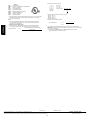
5. Open the electric heater section, compressor section, and
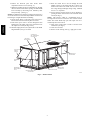
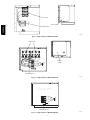
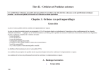
indoor fan section access doors. (See Fig. 1.)
50PG03−16
11. Route the control wires to the left through the foam
bushing. Connect to the mating plug (PL−3) in the wire
harness in the indoor fan section. Do not route 24 volt
low voltage wiring beside high voltage wiring. Maintain
at least a 1−2” separation.
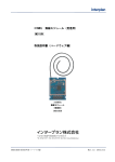
12. Set the manual reset limit switch on the fan housing by
pressing the button located between the terminals on the
switch. (See Fig. 3.)
NOTE: This switch is added as a supplemental means to
de−energize the electric heat contactor in case of indoor airflow
failure. The switch should only open and require reset for a
switch temperature above 200_F.
13. Apply heater wiring label to inside of electric heater
section door. (See Fig. 5.)
14. Close all access doors.
15. Remove “Lock−Out Tag−Out” tag. Apply power to unit.
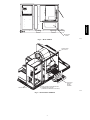
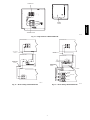
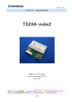
6. Remove the block-off plate from electric heater
compartment and save screws. (See Fig. 2.)
7. Slide heater module into heater compartment by aligning
the heater frame with the heater opening. Do NOT handle
heater assembly by the heating coils. Handle by sheet
metal panel only. (See Fig. 3.)
NOTE: The 50PG16 heater bottom-rear flange will secure into a
slot on the internal cross rail when fully installed. Check that the
heater flange is straight and flat before installing.
8. Secure electric heater to unit using screws from item 6.
Heater will attach to the block off plate screw holes.
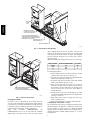
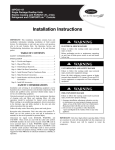
9. Route heater power wires to the left through the foam
bushing and to the single point power connection box in
the compressor section. (See Fig. 3 and 4.)
10. Install the single point box, if required. Refer to the Install
Single Point Box, Step 2, for details.
CONTROL BOX
AND COMPRESSOR
ACCESS DOOR
ELECTRICAL
OPTIONS PANEL
INDOOR MOTOR
ACCESS DOOR
OUTDOOR AIR
SCREEN
(HIDDEN)
CONDENSER COIL
ACCESS PANEL
ECONOMIZER
HOOD
BAROMETRIC
RELIEF DAMPER
HOOD
FILTER ACCESS DOOR
ELECTRIC HEAT
ACCESS DOOR
BASEPAN CONNECTIONS
ACCESS PANEL
C06182
Fig. 1 − Panel Locations
2
50PG03−16
BLOCK-OFF
PLATE
C06183
Fig. 2 − Block−Off Plate
MANUAL RESET
LIMIT SWITCH
ACCESSORY
ELECTRIC
HEATER
ASSEMBLY
SINGLE POINT BOX
ROUTE HEATER POWER WIRES BEHIND
COMPRESSORS AS SHOWN.
(COMPRESSORS REMOVED FOR CLARITY)
C06184
Fig. 3 − Electric Heater Installation
3
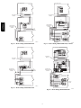
50PG03−16
SINGLE
POINT
BOX
POWER WIRES ARE
ROUTED INTO BOTTOM
OF SINGLE POINT BOX
ROUTE HEATER POWER WIRES
THROUGH RACEWAY AND BEHIND
COMPRESSORS (COMPRESSORS
REMOVED FOR CLARITY)
CONNECT PL3 PLUG
AND RECEPTACLE
HEATER ASSEMBLY
C06185
Fig. 4 − Electric Heater Wire Routing
only a terminal block; no fuses are provided. Fuses are not
required per the National Electrical Code in these single point
accessories since the circuit is below 60 amps. Field−supplied
pressure connectors (Kerneys) may be used in place of these
single point boxes.
All fuses provided in the single point boxes are rated at 60 amps.
UNIT VOLTAGE
208/230
460
575
FUSE VOLTAGE RATING
250
600
600
UL CLASS
RK5
T
T
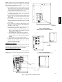
To install single point box:
1. Remove single point box access panel located on the end
of the unit. Save panel and screws. (See Fig. 3.)
2. Using the screws provided, install the terminal blocks and
fuse blocks (if required). (See Fig. 6-12.)
3. If required, using the wires provided, connect the terminal
block to the fuse block. (See Fig. 13-22.)
4. Route power wires from the control box and electric
heaters into the single point box. Route power wires from
the disconnect into the single point box through power
entry hole located next to the access panel. Make all
wiring connections.
5. If single point box has fuses, install hinged cover using
rivets provided. Install magnetic latch in rectangular hole.
(See Fig. 7-10 and 12.)
6. Install wiring label on back of single point box access
panel or on hinged cover.
7. Replace single point box access panel removed in item 1.
Configuring the ComfortLinkt Control
The ComfortLink control must be configured for Electric Heat
(default is No Heat). In addition, if a single-stage electric heater
has been installed, it will be necessary to change the N.HTR
configuration (2 is the default setting). These configurations are
changed through the Scrolling Marquee Display or a Carrier
network device.
AFFIX HEATER WIRING LABEL DIAGRAM
SUPPLIED WITH HEATERS ON
FOIL FACE INSULATION IN AREA SHOWN
C06186
Fig. 5 − Heater Label Location
Install Single Point Box
See Tables 1 and 2 to determine the correct single point box
accessory for the selected heater. The appropriate single point box
is determined by the MOCP (maximum overcurrent protection)
for the heater and unit combination. Refer to the correct figure for
correct installation of the single point box components.
Single
point
accessories
CRSINGLE028A00
and
CRSINGLE030A00 are for use on units where the combined
MOCP rating is less than 60 amps. These accessories contain
4
50PG03−16
NOTE: Consult the Controls and Troubleshooting Guide for in
depth instructions on using and configuring the ComfortLink
control. The following instructions are written for the Scrolling
Marquee Display or Navigator™ accessory.
1. The ComfortLink control must be configured to use the
electric heater accessory. A password may be required to
edit the configurations depending on the previous settings
configured in the unit. Default password is “1111.”
2. To configure the ComfortLink control, use the arrow keys
to scroll the red LED on the display to the “Configuration”
position and press ENTER.
3. Use the arrow keys to scroll down until the display shows
“HEAT.” This is the Heating Configuration Sub Mode.
Press ENTER.
4. The ComfortLink control will display the Type of Heat
(HT.TY) setting. Press ENTER once to select the HT.TY
setting for configuration. Press ENTER again. A “0” will
begin flashing.
5. Use the arrow keys to change the configuration from “0”
(No Heat) to “2” (Electric Heat) and press ENTER. Press
ESCAPE to save the setting.
6. For single-stage electric heaters only (10 kW or less), the
Number of Heat Stages must be changed from 2 to 1.
a. Use the arrow keys to scroll down to the Number of Heat
Stages setting (N.HTR). Press ENTER to select the
N.HTR setting for configuration.
b. Press ENTER again. Configuration value will flash.
c. Use the arrow keys to change the configuration from “2”
(2 stages of heat) to “1” (one stage of heat) and press
ENTER.
d. Press ESCAPE to save the configuration change.
7. Configuration of ComfortLink™ control is now complete.
Pressing ESCAPE multiple times will return the
display to the auto-scroll setting.
8. Close and secure all access doors.
THERMOSTAT CONTROL
For heat mode to operate, the accessory thermostat must be
connected to the corresponding W1 and W2 terminals on the field
connection terminal board located in the unit control box.
SPACE TEMPERATURE CONTROL
(Direct Wired or CCN)
For heat mode to operate, a jumper must be connected between R
and W1 on the field-connection terminal board located in the unit
control box.
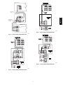
TERMINAL
BLOCKS
(3-PHASE SHOWN)
C06187
Fig. 6 − Single Point Box
CRSINGLE028A00, CRSINGLE030A00
FUSE BLOCK
(3-PHASE SHOWN)
HINGED COVER
C06188
Fig. 7 − Single Point Box
CRSINGLE029A00, CRSINGLE031A00
FUSE BLOCK
TERMINAL BLOCK
HINGED COVER
C06189
Fig. 8 − Single Point Box CRSINGLE032A00
5
FUSE BLOCK
50PG03−16
HINGED COVER
TERMINAL BLOCK
C06190
Fig. 9 − Single Point Box CRSINGLE033A00
FUSE BLOCK
HINGED
COVER
TERMINAL BLOCK
C06191
Fig. 10 − Single Point Box CRSINGLE034A00
TERMINAL BLOCK
C06192
Fig. 11 − Single Point Box CRSINGLE035A00
6
FUSE BLOCK
50PG03−16
HINGED
COVER
TERMINAL BLOCK
C06192
Fig. 12 − Single Point Box CRSINGLE036A00
UNIT CONTROL BOX
UNIT CONTROL BOX
UNIT POWER
PIGTAILS
UNIT POWER
PIGTAILS
SINGLE POINT BOX
SINGLE POINT BOX
FB1
TO
FIELD
POWER
HEATER WIRES
SUPPLIED WITH
HEATERS
TO
FIELD
POWER
HEATER WIRES
SUPPLIED WITH
HEATERS
12 GA WIRES
HEATERS
HEATERS
15-25 kW ONLY
FUSE BLOCK
FUSE BLOCK
25 kW ONLY
FUSE BLOCK
FUSE BLOCK
C06194
C06195
Fig. 13 − Heater Wiring CRSINGLE028A00
Fig. 14 − Heater Wiring CRSINGLE029A00
7
UNIT CONTROL BOX
UNIT CONTROL BOX
UNIT POWER
PIGTAILS
UNIT POWER
PIGTAILS
SINGLE POINT BOX
SINGLE POINT BOX
50PG03−16
FB1
TO
FIELD
POWER
HEATER WIRES
SUPPLIED WITH
HEATERS
HEATER WIRES
SUPPLIED WITH
HEATERS
TO
FIELD
POWER
HEATERS
HEATERS
FUSE BLOCK
FUSE BLOCK
FUSE BLOCK
FUSE BLOCK
C06196
C06198
Fig. 15 − Heater Wiring CRSINGLE030A00
Fig. 17 − Heater Wiring CRSINGLE031A00, 35−50 kW
UNIT CONTROL BOX
UNIT CONTROL BOX
UNIT POWER
PIGTAILS
UNIT POWER
PIGTAILS
SINGLE POINT BOX
FB1
TB1
TO
FIELD
POWER
HEATER WIRES
SUPPLIED WITH
HEATERS
TO
FIELD
POWER
HEATER WIRES
SUPPLIED WITH
HEATERS
SINGLE POINT BOX
HEATERS
HEATERS
35-60 kW ONLY
FUSE BLOCK
FUSE BLOCK
FUSE BLOCK
60 kW
ONLY
C06197
Fig. 16 − Heater Wiring CRSINGLE031A00
C06199
Fig. 18 − Heater Wiring CRSINGLE032A00
8
UNIT CONTROL BOX
UNIT POWER
PIGTAILS
SINGLE POINT BOX
50PG03−16
FB1
TB1
HEATER WIRES
SUPPLIED WITH
HEATERS
TO
FIELD
POWER
FUSE BLOCK
HEATERS
40,50,60 kW ONLY
FUSE BLOCK
C06202
Fig. 21 − Heater Wiring CRSINGLE035A00
C06200
Fig. 19 − Heater Wiring CRSINGLE033A00
C06203
Fig. 22 − Heater Wiring CRSINGLE036A00
C06201
Fig. 20 − Heater Wiring CRSINGLE034A00
9
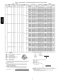
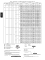
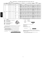
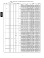
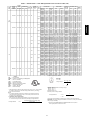
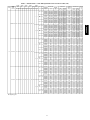
Table 1 — Electrical Data — Units Without Optional Powered Convenience Outlet
UNIT
50PG
NOMINAL
POWER
SUPPLY
VOLTS−PH−HZ
VOLTAGE
RANGE
MIN
MAX
COMPRESSOR
(EA)
RLA
OFM
FLA
IFM
FLA
LRA
POWER
EXHAUST
FLA
ELECTRIC HEAT
IFM
TYPE
CRHEATER
PART NO.
FLA
NOMINAL
KW*
MCA
MOCP{
CRSINGLE
PART NO.
(Note 3)
200A00
201A00
202A00
203A00
200A00
201A00
202A00
203A00
200A00
201A00
202A00
203A00
200A00
201A00
202A00
203A00
200A00
201A00
202A00
203A00
204A00
200A00
201A00
202A00
203A00
204A00
200A00
201A00
202A00
203A00
204A00
200A00
201A00
202A00
203A00
204A00
207A00
208A00
209A00
210A00
211A00
207A00
208A00
209A00
210A00
211A00
10.8/12.5
17.3/20.0
26.0/30.0
34.7/40.0
10.8/12.5
17.3/20.0
26.0/30.0
34.7/40.0
10.8/12.5
17.3/20.0
26.0/30.0
34.7/40.0
10.8/12.5
17.3/20.0
26.0/30.0
34.7/40.0
10.8/12.5
17.3/20.0
26.0/30.0
34.7/40.0
52.0/60.0
10.8/12.5
17.3/20.0
26.0/30.0
34.7/40.0
52.0/60.0
10.8/12.5
17.3/20.0
26.0/30.0
34.7/40.0
52.0/60.0
10.8/12.5
17.3/20.0
26.0/30.0
34.7/40.0
52.0/60.0
6.3/7.2
10.0/11.5
15.0/17.3
20.0/23.1
30.0/34.6
6.3/7.2
10.0/11.5
15.0/17.3
20.0/23.1
30.0/34.6
/
2.3/3.0
3.8/5.0
5.6/7.5
7.5/10.0
/
2.3/3.0
3.8/5.0
5.6/7.5
7.5/10.0
/
2.3/3.0
3.8/5.0
5.6/7.5
7.5/10.0
/
2.3/3.0
3.8/5.0
5.6/7.5
7.5/10.0
/
2.3/3.0
3.8/5.0
5.6/7.5
7.5/10.0
11.3/15.0
/
2.3/3.0
3.8/5.0
5.6/7.5
7.5/10.0
11.3/15.0
/
2.3/3.0
3.8/5.0
5.6/7.5
7.5/10.0
11.3/15.0
/
2.3/3.0
3.8/5.0
5.6/7.5
7.5/10.0
11.3/15.0
/
2.3/3.0
3.8/5.0
5.6/7.5
7.5/10.0
11.3/15.0
/
2.3/3.0
3.8/5.0
5.6/7.5
7.5/10.0
11.3/15.0
21.8/21.8
21.8/21.8
27.8/31.1
38.6/43.6
49.5/56.1
21.8/21.8
21.8/21.8
27.8/31.1
38.6/43.6
49.5/56.1
23.2/23.2
23.2/23.5
29.5/32.9
40.4/45.4
51.2/57.9
23.2/23.2
23.2/23.5
29.5/32.9
40.4/45.4
51.2/57.9
25.0/25.0
25.0/25.0
27.8/31.1
38.6/43.6
49.5/56.1
71.1/81.1
25.0/25.0
25.0/25.0
27.8/31.1
38.6/43.6
49.5/56.1
71.1/81.1
26.4/26.4
26.4/26.4
29.5/32.9
40.4/45.4
51.2/57.9
72.9/82.9
26.4/26.4
26.4/26.4
29.5/32.9
40.4/45.4
51.2/57.9
72.9/82.9
20.2/20.2
20.2/20.2
20.2/20.6
24.9/27.8
31.1/35.0
43.6/49.4
20.2/20.2
20.2/20.2
20.2/20.6
24.9/27.8
31.1/35.0
43.6/49.4
30/30
30/30
30/35
40/45
50/60
30/30
30/30
30/35
40/45
50/60
30/30
30/30
30/35
45/50
60/60
30/30
30/30
30/35
45/50
60/60
30/30
30/30
30/40
40/45
50/60
80/90
30/30
30/30
30/40
40/45
50/60
80/90
40/40
40/40
40/40
45/50
60/60
80/90
40/40
40/40
40/40
45/50
60/60
80/90
30/30
30/30
30/30
30/30
35/40
45/50
30/30
30/30
30/30
30/30
35/40
45/50
028A00
028A00
028A00
028A00
028A00
028A00
028A00
028A00
028A00
028A00
028A00
028A00
028A00
028A00
028A00
028A00
028A00
028A00
028A00
028A00
029A00
028A00
028A00
028A00
028A00
029A00
028A00
028A00
028A00
028A00
029A00
028A00
028A00
028A00
028A00
029A00
030A00
030A00
030A00
030A00
030A00
030A00
030A00
030A00
030A00
030A00
Low
High
208/230-1-60
187
253
12.8
60
0.9
4.9
50PG03−16
03
Low
1.4
High
Low
High
208/230-1-60
187
253
15.4
83
0.9
4.9
Low
04
1.4
High
Low
208/230-3-60
187
253
11.5
77
0.9
4.9
High
FLA
HACR
IFM
LRA
MCA
MOCP
NEC
OFM
RLA
−
−
−
−
−
−
−
−
−
LEGEND
Full Load Amps
Heating, Air Conditioning and Refrigeration
Indoor − Fan Motor
Locked Rotor Amps
Minimum Circuit Amps
Maximum Overcurrent Protection
National Electrical Code
Outdoor−Fan Motor
Rated Load Amps
*
Heater capacity (kW) is based on heater voltage of 208 v, 240 v, or 480 v. If power distribution voltage to unit varies from rated heater voltage, heater kW will vary accordingly.
† Fuse or HACR circuit breaker.
NOTES:
1. In compliance with NEC requirements for multimotor and combination load equipment (refer to NEC Articles 430 and 440), the overcurrent protective device for the
unit shall be fuse or HACR breaker.
2. Unbalanced 3-Phase Supply Voltage
Never operate a motor where a phase imbalance in supply voltage is greater than
2%. Use the following formula to determine the percentage of voltage imbalance.
max voltage deviation from average voltage
% Voltage Imbalance
= 100 x
POWER SUPPLY
DISCONNECT
SIZE
FLA
LRA
21/21
21/21
26/29
36/40
45/52
21/21
21/21
26/29
36/40
45/52
23/23
23/23
27/30
37/42
47/53
23/23
23/23
27/30
37/42
47/53
24/24
24/24
26/29
36/40
45/52
65/75
24/24
24/24
26/29
36/40
45/52
65/75
26/26
26/26
27/30
37/42
47/53
67/76
26/26
26/26
27/30
37/42
47/53
67/76
20/20
20/20
20/20
23/26
29/32
40/45
20/20
20/20
20/20
23/26
29/32
40/45
73/73
73/73
73/73
73/73
73/73
73/73
73/73
73/73
73/73
73/73
75/75
75/75
75/75
75/75
75/75
75/75
75/75
75/75
75/75
75/75
96/96
96/96
96/96
96/96
96/96
96/96
96/96
96/96
96/96
96/96
96/96
96/96
98/98
98/98
98/98
98/98
98/98
98/98
98/98
98/98
98/98
98/98
98/98
98/98
90/90
90/90
90/90
90/90
90/90
90/90
90/90
90/90
90/90
90/90
90/90
90/90
WIRING
FIG. NO.
13
13
13
13
13
13
13
13
13
13
13
13
13
13
13
13
13
13
13
13
14
13
13
13
13
14
13
13
13
13
14
13
13
13
13
14
15
15
15
15
15
15
15
15
15
15
Example: Supply voltage is 460-3-60
AB = 224 v
BC = 231 v
AC = 226 v
Average Voltage =
=
=
224 + 231 + 226
3
681
3
227
Determine maximum deviation from average voltage.
(AB) 227 – 223 = 3 v
(BC) 231 – 227 = 4 v
(AC) 227 – 226 = 1 v
Maximum deviation is 4 v.
Determine percent of voltage imbalance.
4
% Voltage Imbalance
= 100 x
227
= 1.76%
This amount of phase imbalance is satisfactory as it is below the maximum allowable 2%.
IMPORTANT: If the supply voltage phase imbalance is more than 2%, contact your local electric
utility company immediately.
average voltage
3. Single point kits CRSINGLE028A00 and CRSINGLE030A00 are not required if
field−supplied pressure connectors are used.
10
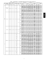
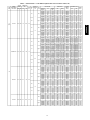
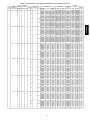
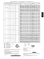
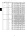
Table 1 — Electrical Data — Units Without Optional Powered Convenience Outlet (cont)
NOMINAL
POWER SUPPLY
VOLTS−PH−HZ
MIN
MAX
COMPRESSOR
(EA)
RLA
LRA
OFM
FLA
IFM
FLA
POWER
EXHAUST
FLA
ELECTRIC HEAT
IFM
TYPE
Low
208/230-3-60
(cont)
187
253
11.5
77
0.9
4.9
1.4
High
Low
High
04
(cont)
460-3-60
414
506
5.1
35
0.5
2.1
Low
0.6
High
Low
High
575-3-60
518
632
4.3
31.0
0.4
2.2
Low
1.4
High
4.9
Low
208/230-1-60
187
253
20.5
109
7.0
High
4.9
Low
0.9
05
1.4
208/230-3-60
187
253
14.6
91
7.0
High
4.9
Low
0.9
5.2
High
CPHEATER
PART NO.
207A00
208A00
209A00
210A00
211A00
207A00
208A00
209A00
210A00
211A00
214A00
215A00
216A00
217A00
218A00
214A00
215A00
216A00
217A00
218A00
214A00
215A00
216A00
217A00
218A00
214A00
215A00
216A00
217A00
218A00
221A00
222A00
221A00
222A00
221A00
222A00
221A00
222A00
201A00
202A00
203A00
204A00
205A00
201A00
202A00
203A00
204A00
205A00
201A00
202A00
203A00
204A00
205A00
201A00
202A00
203A00
204A00
205A00
208A00
209A00
210A00
211A00
212A00
208A00
209A00
210A00
211A00
212A00
POWER SUPPLY
FLA
NOMINAL
KW*
MCA
MOCP†
CRSINGLE
PART NO.
(NOTE3)
6.3/7.2
10.0/11.5
15.0/17.3
20.0/23.1
30.0/34.6
6.3/7.2
10.0/11.5
15.0/17.3
20.0/23.1
30.0/34.6
3.5
5.8
8.7
11.5
17.3
3.5
5.8
87
11.5
17.3
3.5
5.8
8.7
11.5
17.3
3.5
5.8
8.7
11.5
17.3
9.2
13.9
9.2
13.9
9.2
13.9
9.2
13.9
17.3/20.0
26.0/30.0
34.7/40.0
52.0/60.0
69.3/80.0
17.3/20.0
26.0/30.0
34.7/40.0
52.0/60.0
69.3/80.0
17.3/20.0
26.0/30.0
34.7/40.0
52.0/60.0
69.3/80.0
17.3/20.0
26.0/30.0
34.7/40.0
52.0/60.0
69.3/80.0
10.0/11.5
15.0/17.3
20.0/23.1
30.0/34.6
40.0/46.2
10.0/11.5
15.0/17.3
20.0/23.1
30.0/34.6
40.0/46.2
/
2.3/3.0
3.8/5.0
5.6/7.5
7.5/10.0
11.3/15.0
/
2.3/3.0
3.8/5.0
5.6/7.5
7.5/10.0
11.3/15.0
3.0
5.0
7.5
10.0
15.0
3.0
5.0
7.5
10.0
15.0
3.0
5.0
7.5
10.0
15.0
3.0
5.0
7.5
10.0
15.0
10.0
15.0
10.0
15.0
10.0
15.0
10.0
15.0
/
3.8/5.0
5.6/7.5
7.5/10.0
11.3/15.0
15.0/20.0
/
3.8/5.0
5.6/7.5
7.5/10.0
11.3/15.0
15.0/20.0
/
3.8/5.0
5.6/7.5
7.5/10.0
11.3/15.0
15.0/20.0
/
3.8/5.0
5.6/7.5
7.5/10.0
11.3/15.0
15.0/20.0
/
3.8/5.0
5.6/7.5
7.5/10.0
11.3/15.0
15.0/20.0
/
3.8/5.0
5.6/7.5
7.5/10.0
11.3/15.0
15.0/20.0
21.6/21.6
21.6/21.6
21.6/22.3
26.6/29.5
32.9/36.7
45.4/51.2
21.6/21.6
21.6/21.6
21.6/22.3
26.6/29.5
32.9/36.7
45.4/51.2
9.0
9.0
9.8
13.5
17.1
24.3
9.0
9.0
9.8
13.5
17.1
24.3
9.6
9.6
10.6
14.2
17.8
25.0
9.6
9.6
10.6
14.2
17.8
25.0
8.0
14.1
20.0
8.0
14.1
20.0
9.4
15.9
21.8
9.4
15.9
21.8
31.4/31.4
31.4/31.4
38.6/43.6
49.5/56.1
71.1/81.1
92.8/106.1
33.5/33.5
33.5/33.8
41.2/46.3
52.1/58.8
73.7/83.8
95.4/108.8
32.8/32.8
32.8/32.9
40.4/45.4
51.2/57.9
72.9/82.9
94.5/107.9
34.9/34.9
34.9/35.5
43.0/48.0
53.8/60.5
75.5/85.5
97.2/110.5
24.0/24.0
24.0/24.0
24.9/27.8
31.1/35.0
43.6/49.4
56.2/63.9
24.3/24.3
24.3/24.3
25.3/28.2
31.5/35.4
44.0/49.8
56.5/64.2
30/30
30/30
30/30
30/30
35/40
50/60
30/30
30/30
30/30
30/30
35/40
50/60
15
15
15
15
20
25
15
15
15
15
20
25
15
15
15
15
20
30
15
15
15
15
20
30
15
15
25
15
15
25
15
20
25
15
20
25
50/50
50/50
50/50
50/60
80/90
100/110
50/50
50/50
50/50
60/60
80/90
100/110
50/50
50/50
50/50
60/60
80/90
100/110
50/50
50/50
50/50
60/70
80/90
100/125
30/30
30/30
30/30
35/40
45/50
60/70
30/30
30/30
30/30
35/40
45/50
60/70
030A00
030A00
030A00
030A00
030A00
030A00
030A00
030A00
030A00
030A00
030A00
030A00
030A00
030A00
030A00
030A00
030A00
030A00
030A00
030A00
030A00
030A00
030A00
030A00
030A00
030A00
030A00
030A00
030A00
030A00
030A00
030A00
030A00
030A00
030A00
030A00
030A00
030A00
028A00
028A00
028A00
029A00
029A00
028A00
028A00
028A00
029A00
029A00
028A00
028A00
028A00
029A00
029A00
028A00
028A00
028A00
029A00
029A00
030A00
030A00
030A00
030A00
031A00
030A00
030A00
030A00
030A00
031A00
11
DISCONNECT SIZE
FLA
LRA
22/22
22/22
22/22
25/27
30/34
42/47
22/22
22/22
22/22
25/27
30/34
42/47
9
9
9
12
16
22
9
9
9
12
16
22
10
10
10
13
16
23
10
10
10
13
16
23
8
13
18
8
13
18
10
15
20
10
15
20
30/30
30/30
36/40
45/52
65/76
85/98
33/33
33/33
38/43
48/54
68/77
88/100
32/32
32/32
37/42
47/53
67/76
87/99
34/34
34/34
40/44
50/56
69/79
89/102
23/23
23/23
23/26
29/32
40/45
52/59
24/24
24/24
24/26
29/33
41/46
52/59
92/92
92/92
92/92
92/92
92/92
92/92
92/92
92/92
92/92
92/92
92/92
92/92
42
42
42
42
42
42
42
42
42
42
42
42
43
43
43
43
43
43
43
43
43
43
43
43
37
37
37
37
37
37
39
39
39
39
39
39
122/122
122/122
122/122
122/122
122/122
122/122
148/148
148/148
148/148
148/148
148/148
148/148
124/124
124/124
124/124
124/124
124/124
124/124
150/150
150/150
150/150
150/150
150/150
150/150
104/104
104/104
104/104
104/104
104/104
104/104
123/123
123/123
123/123
123/123
123/123
123/123
WIRING
FIG. NO.
15
15
15
15
15
15
15
15
15
15
15
15
15
15
15
15
15
15
15
15
15
15
15
15
15
15
15
15
15
15
15
15
15
15
15
15
15
15
13
13
13
14
14
13
13
13
14
14
13
13
13
14
14
13
13
13
14
14
15
15
15
15
16
15
15
15
15
16
50PG03−16
UNIT
50PG
VOLTAGE
RANGE
Table 1 — Electrical Data — Units Without Optional Powered Convenience Outlet (cont)
UNIT
50PG
NOMINAL
POWER
SUPPLY
VOLTS−PH−HZ
VOLTAGE
RANGE
MIN
MAX
COMPRESSOR
(EA)
RLA
LRA
OFM
FLA
IFM
FLA
POWER
EXHAUST
FLA
4.9
187 253
14.6
91
0.9
50PG03−16
208/230-3-60
(cont)
ELECTRIC HEAT
IFM
TYPE
Low
1.4
5.2
High
2.1
Low
460-3-60
414 506
7.1
46
2.6
High
2.1
Low
0.5
05
(cont)
0.6
2.6
High
Low
High
575-3-60
518 632
5.0
34.0
0.4
2.0
Low
1.4
High
FLA
HACR
IFM
LRA
MCA
MOCP
NEC
OFM
RLA
−
−
−
−
−
−
−
−
−
FLA
NOMINAL
KW*
MCA
MOCP†
CRSINGLE
PART NO.
(NOTE3)
208A00
209A00
210A00
211A00
212A00
208A00
209A00
210A00
211A00
212A00
215A00
216A00
217A00
218A00
219A00
215A00
216A00
217A00
218A00
219A00
215A00
216A00
217A00
218A00
219A00
215A00
216A00
217A00
218A00
219A00
221A00
222A00
223A00
221A00
222A00
223A00
221A00
222A00
223A00
221A00
222A00
223A00
10.0/11.5
15.0/17.3
20.0/23.1
30.0/34.6
40.0/46.2
10.0/11.5
15.0/17.3
20.0/23.1
30.0/34.6
40.0/46.2
5.8
8.7
11.5
17.3
23.1
5.8
8.7
11.5
17.3
23.1
5.8
8.7
11.5
17.3
23.1
5.8
8.7
11.5
17.3
23.1
9.2
13.9
18.5
9.2
13.9
18.5
9.2
13.9
18.5
9.2
13.9
18.5
/
3.8/5.0
5.6/7.5
7.5/10.0
11.3/15.0
15.0/20.0
/
3.8/5.0
5.6/7.5
7.5/10.0
11.3/15.0
15.0/20.0
5.0
7.5
10.0
15.0
20.0
5.0
7.5
10.0
15.0
20.0
5.0
7.5
10.0
15.0
20.0
5.0
7.5
10.0
15.0
20.0
10.0
15.0
20.0
10.0
15.0
20.0
10.0
15.0
20.0
10.0
15.0
20.0
25.4/25.4
25.4/25.4
26.6/29.5
32.9/36.7
45.4/51.2
57.9/65.6
25.7/25.7
25.7/25.7
27.0/29.9
33.3/37.1
45.8/51.6
58.3/66.0
11.4
11.4
13.5
17.1
24.3
31.5
11.9
11.9
14.1
17.7
24.9
32.1
12.0
12.0
14.2
17.8
25.0
32.2
12.5
12.5
14.8
18.4
25.7
32.9
9.0
14.1
20.0
25.8
8.9
14.0
19.9
25.6
10.4
15.9
21.8
27.5
10.3
15.8
21.6
27.4
30/30
30/30
30/30
40/40
50/60
60/70
30/30
30/30
30/30
40/40
50/60
60/70
15
15
15
20
25
35
15
15
15
20
25
35
15
15
15
20
30
35
15
15
15
20
30
35
15
15
25
30
15
15
20
30
15
20
25
30
15
20
25
30
030A00
030A00
030A00
030A00
031A00
030A00
030A00
030A00
030A00
031A00
030A00
030A00
030A00
030A00
030A00
030A00
030A00
030A00
030A00
030A00
030A00
030A00
030A00
030A00
030A00
030A00
030A00
030A00
030A00
030A00
030A00
030A00
030A00
030A00
030A00
030A00
030A00
030A00
030A00
030A00
030A00
030A00
LEGEND
Full Load Amps
Heating, Air Conditioning and Refrigeration
Indoor − Fan Motor
Locked Rotor Amps
Minimum Circuit Amps
Maximum Overcurrent Protection
National Electrical Code
Outdoor−Fan Motor
Rated Load Amps
*
Heater capacity (kW) is based on heater voltage of 208 v, 240 v, or 480 v. If power distribution voltage to unit varies from rated heater voltage, heater kW will vary accordingly.
† Fuse or HACR circuit breaker.
NOTES:
1. In compliance with NEC requirements for multimotor and combination load equipment (refer to NEC Articles 430 and 440), the overcurrent protective device for the
unit shall be fuse or HACR breaker.
2. Unbalanced 3-Phase Supply Voltage
Never operate a motor where a phase imbalance in supply voltage is greater than
2%. Use the following formula to determine the percentage of voltage imbalance.
max voltage deviation from average voltage
% Voltage Imbalance
= 100 x
POWER SUPPLY
CRHEATER
PART NO.
DISCONNECT SIZE
FLA
LRA
25/25
25/25
25/27
30/34
42/47
53/60
25/25
25/25
25/28
31/34
42/47
54/61
11
11
12
16
22
29
12
12
13
16
23
30
12
12
13
16
23
30
12
12
14
17
24
30
9
13
18
24
9
13
18
24
10
15
20
25
10
14
20
25
106/106
106/106
106/106
106/106
106/106
106/106
125/125
125/125
125/125
125/125
125/125
125/125
53
53
53
53
53
53
62
62
62
62
62
62
54
54
54
54
54
54
63
63
63
63
63
63
40
40
40
40
46
46
46
46
42
42
42
42
48
48
48
48
WIRING
FIG. NO.
15
15
15
15
16
15
15
15
15
16
15
15
15
15
15
15
15
15
15
15
15
15
15
15
15
15
15
15
15
15
15
15
15
15
15
15
15
15
15
15
15
15
Example: Supply voltage is 460-3-60
AB = 224 v
BC = 231 v
AC = 226 v
Average Voltage =
=
=
224 + 231 + 226
3
681
3
227
Determine maximum deviation from average voltage.
(AB) 227 – 223 = 3 v
(BC) 231 – 227 = 4 v
(AC) 227 – 226 = 1 v
Maximum deviation is 4 v.
Determine percent of voltage imbalance.
4
% Voltage Imbalance
= 100 x
227
= 1.76%
This amount of phase imbalance is satisfactory as it is below the maximum allowable 2%.
IMPORTANT: If the supply voltage phase imbalance is more than 2%, contact your local electric
utility company immediately.
average voltage
3. Single point kits CRSINGLE028A00 and CRSINGLE030A00 are not required if
field−supplied pressure connectors are used.
12
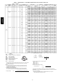
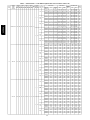
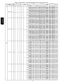
Table 1 — Electrical Data — Units Without Optional Powered Convenience Outlet (cont)
NOMINAL
POWER SUPPLY
VOLTS-PH-HZ
VOLTAGE
RANGE
MIN
MAX
COMPRESSOR
(EA)
RLA
LRA
OFM
IFM
FLA
FLA
POWER
EXHAUST
FLA
4.9
TYPE
Low
208/230-1-60
187 253
26.9
145
7.0
High
4.9
Low
1.5
1.4
7.0
High
Low
High
06
208/230-3-60
187 253
17.6
123
1.5
5.2
Low
1.4
High
Low
High
460-3-60
414 506
7.7
50
0.8
ELECTRIC HEAT
IFM
2.6
Low
0.6
High
POWER SUPPLY
CPHEATER
PART NO.
FLA
NOMINAL
KW*
MCA
MOCP†
PRSINGLE
PART N0.
(NOTE3)
201A00
202A00
203A00
204A00
205A00
206A00
201A00
202A00
203A00
204A00
205A00
206A00
201A00
202A00
203A00
204A00
205A00
206A00
201A00
202A00
203A00
204A00
205A00
206A00
208A00
209A00
210A00
211A00
212A00
213A00
208A00
209A00
210A00
211A00
212A00
213A00
208A00
209A00
210A00
211A00
212A00
213A00
208A00
209A00
210A00
211A00
212A00
213A00
215A00
216A00
217A00
218A00
219A00
220A00
215A00
216A00
217A00
218A00
219A00
220A00
215A00
216A00
217A00
218A00
219A00
220A00
215A00
216A00
217A00
218A00
219A00
220A00
17.3/20.0
26.0/30.0
34.7/40.0
52.0/60.0
69.3/80.0
86.7/100.0
17.3/20.0
26.0/30.0
34.7/40.0
52.0/60.0
69.3/80.0
86.7/100.0
17.3/20.0
26.0/30.0
34.7/40.0
52.0/60.0
69.3/80.0
86.7/100.0
17.3/20.0
26.0/30.0
34.7/40.0
52.0/60.0
69.3/80.0
86.7/100.0
10.0/11.5
15.0/17.3
20.0/23.1
30.0/34.6
40.0/46.2
50.0/57.7
10.0/11.5
15.0/17.3
20.0/23.1
30.0/34.6
40.0/46.2
50.0/57.7
10.0/11.5
15.0/17.3
20.0/23.1
30.0/34.6
40.0/46.2
50.0/57.7
10.0/11.5
15.0/17.3
20.0/23.1
30.0/34.6
40.0/46.2
50.0/57.7
5.8
8.7
11.5
17.3
23.1
28.9
5.8
8.7
11.5
17.3
23.1
28.9
5.8
8.7
11.5
17.3
23.1
28.9
5.8
8.7
11.5
17.3
23.1
28.9
/
3.8/5.0
5.6/7.5
7.5/10.0
11.3/15.0
15.0/20.0
18.8/25.0
/
3.8/5.0
5.6/7.5
7.5/10.0
11.3/15.0
15.0/20.0
18.8/25.0
/
3.8/5.0
5.6/7.5
7.5/10.0
11.3/15.0
15.0/20.0
18.8/25.0
/
3.8/5.0
5.6/7.5
7.5/10.0
11.3/15.0
15.0/20.0
18.8/25.0
/
3.8/5.0
5.6/7.5
7.5/10.0
11.3/15.0
15.0/20.0
18.8/25.0
/
3.8/5.0
5.6/7.5
7.5/10.0
11.3/15.0
15.0/20.0
18.8/25.0
/
3.8/5.0
5.6/7.5
7.5/10.0
11.3/15.0
15.0/20.0
18.8/25.0
/
3.8/5.0
5.6/7.5
7.5/10.0
11.3/15.0
15.0/20.0
18.8/25.0
5.0
7.5
10.0
15.0
20.0
25.0
5.0
7.5
10.0
15.0
20.0
25.0
5.0
7.5
10.0
15.0
20.0
25.0
5.0
7.5
10.0
15.0
20.0
25.0
40.1/40.1
40.1/40.1
40.1/43.6
49.5/56.1
71.1/81.1
92.8/106.1
114.4/131.1
42.2/42.2
42.2/42.2
42.2/46.3
52.1/58.8
73.7/83.8
95.4/108.8
117.1/133.8
41.5/41.5
41.5/41.5
41.5/45.4
51.2/57.9
72.9/82.9
94.5/107.9
116.2/132.9
43.6/43.6
43.6/43.6
43.6/48.0
53.8/60.5
75.5/85.5
97.2/110.5
118.8/135.5
28.7/28.7
28.7/28.7
28.7/28.7
31.5/35.4
44.0/49.8
56.5/64.2
69.0/78.7
28.7/28.7
28.7/28.7
28.7/28.7
31.5/35.4
44.0/49.8
56.5/64.2
69.0/78.7
30.1/30.1
30.1/30.1
30.1/30.1
33.3/37.1
45.8/51.6
58.3/66.0
70.8/80.4
30.1/30.1
30.1/30.1
30.1/30.1
33.3/37.1
45.8/51.6
58.3/66.0
70.8/80.4
13.0
13.0
14.1
17.7
24.9
32.1
39.3
13.0
13.0
14.1
17.7
24.9
32.1
39.3
13.6
13.6
14.8
18.4
25.7
32.9
40.1
13.6
13.6
14.8
18.4
25.7
32.9
40.1
60/60
60/60
60/60
50/60
80/90
100/110
125/150
60/60
60/60
60/60
60/60
80/90
100/110
125/150
60/60
60/60
60/60
60/60
80/90
100/110
125/150
60/60
60/60
60/60
60/70
80/90
100/125
125/150
45/45
45/45
45/45
45/45
45/50
60/70
70/80
45/45
45/45
45/45
45/45
45/50
60/70
70/80
45/45
45/45
45/45
45/45
50/60
60/70
80/90
45/45
45/45
45/45
45/45
50/60
60/70
80/90
20
20
20
20
25
35
40
20
20
20
20
25
35
40
20
20
20
20
30
35
45
20
20
20
20
30
35
45
028A00
028A00
028A00
029A00
029A00
029A00
028A00
028A00
028A00
029A00
029A00
029A00
028A00
028A00
028A00
029A00
029A00
029A00
028A00
028A00
028A00
029A00
029A00
029A00
030A00
030A00
030A00
030A00
031A00
031A00
030A00
030A00
030A00
030A00
031A00
031A00
030A00
030A00
030A00
030A00
031A00
031A00
030A00
030A00
030A00
030A00
031A00
031A00
030A00
030A00
030A00
030A00
030A00
030A00
030A00
030A00
030A00
030A00
030A00
030A00
030A00
030A00
030A00
030A00
030A00
030A00
030A00
030A00
030A00
030A00
030A00
030A00
13
DISCONNECT
SIZE
FLA
LRA
38/38
38/38
38/40
45/52
65/75
85/98
105/121
41/41
41/41
41/43
48/54
68/77
88/100
108/123
40/40
40/40
40/42
47/53
67/76
89/99
107/122
42/42
42/42
42/44
50/56
69/79
89/102
109/125
28/28
28/28
28/28
29/33
41/46
52/59
64/72
28/28
28/28
28/28
29/33
41/46
52/59
64/72
30/30
30/30
30/30
31/34
42/47
54/61
65/74
30/30
30/30
30/30
31/34
42/47
54/61
65/74
13
13
13
16
23
30
36
13
13
13
16
23
30
36
13
13
14
17
24
30
37
13
13
14
17
24
30
37
159/159
159/159
159/159
159/159
159/159
159/159
159/159
185/185
185/185
185/185
185/185
185/185
185/185
185/185
161/161
161/161
161/161
161/161
161/161
161/161
161/161
187/187
187/187
187/187
187/187
187/187
187/187
187/187
156/156
156/156
156/156
156/156
156/156
156/156
156/156
156/156
156/156
156/156
156/156
156/156
156/156
156/156
158/158
158/158
158/158
158/158
158/158
158/158
158/158
158/158
158/158
158/158
158/158
158/158
158/158
158/158
67
67
67
67
67
67
67
67
67
67
67
67
67
67
68
68
68
68
68
68
68
68
68
68
68
68
68
68
WIRING
FIG. NO.
13
13
13
14
14
14
13
13
13
14
14
14
13
13
13
14
14
14
13
13
13
14
14
14
15
15
15
15
16
16
15
15
15
15
16
16
15
15
15
15
16
16
15
15
15
15
16
16
15
15
15
15
15
15
15
15
15
15
15
15
15
15
15
15
15
15
15
15
15
15
15
15
50PG03−16
UNIT
50PG
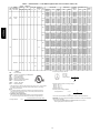
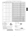
Table 1 — Electrical Data — Units Without Optional Powered Convenience Outlet (cont)
UNIT
50PG
NOMINAL
POWER SUPPLY
VOLTS-PH-HZ
575-3-60
MIN
MAX
518 632
COMPRESSOR
(EA)
RLA
6.1
LRA
40
OFM
IFM
FLA
FLA
0.8
50PG03−16
06
(cont)
VOLTAGE
RANGE
208/230-3-60
187 253
20.5
149
POWER
EXHAUST
FLA
TYPE
Low
and
High
1.4
Low
and
High
5.2
Low
7.5
High
2.0
1.5
5.2
Low
1.4
7.5
High
2.6
Low
07
460-3-60
414 506
9.6
75
3.4
High
2.6
Low
0.8
0.6
3.4
FLA
HACR
IFM
LRA
MCA
MOCP
NEC
OFM
RLA
−
−
−
−
−
−
−
−
−
ELECTRIC HEAT
IFM
High
CRHEATER
PART NO.
FLA
NOMINAL
KW*
MCA
MOCP†
CRSINGLE
PART NO.
(NOTE3)
221A00
222A00
223A00
254A00
221A00
222A00
223A00
254A00
208A00
209A00
210A00
211A00
212A00
213A00
208A00
209A00
210A00
211A00
212A00
213A00
208A00
209A00
210A00
211A00
212A00
213A00
208A00
209A00
210A00
211A00
212A00
213A00
215A00
216A00
217A00
218A00
219A00
220A00
215A00
216A00
217A00
218A00
219A00
220A00
215A00
216A00
217A00
218A00
219A00
220A00
215A00
216A00
217A00
218A00
219A00
220A00
9.2
13.9
18.5
23.1
9.2
13.9
18.5
23.1
10.0/11.5
15.0/17.3
20.0/23.1
30.0/34.6
40.0/46.2
50.0/57.7
10.0/11.5
15.0/17.3
20.0/23.1
30.0/34.6
40.0/46.2
50.0/57.7
10.0/11.5
15.0/17.3
20.0/23.1
30.0/34.6
40.0/46.2
50.0/57.7
10.0/11.5
15.0/17.3
20.0/23.1
30.0/34.6
40.0/46.2
50.0/57.7
5.8
8.7
11.5
17.3
23.1
28.9
5.8
8.7
11.5
17.3
23.1
28.9
5.8
8.7
11.5
17.3
23.1
28.9
5.8
8.7
11.5
17.3
23.1
28.9
10.0
15.0
20.0
25.0
10.0
15.0
20.0
25.0
/
3.8/5.0
5.6/7.5
7.5/10.0
11.3/15.0
15.0/20.0
18.8/25.0
/
3.8/5.0
5.6/7.5
7.5/10.0
11.3/15.0
15.0/20.0
18.8/25.0
/
3.8/5.0
5.6/7.5
7.5/10.0
11.3/15.0
15.0/20.0
18.8/25.0
/
3.8/5.0
5.6/7.5
7.5/10.0
11.3/15.0
15.0/20.0
18.8/25.0
5.0
7.5
10.0
15.0
20.0
25.0
5.0
7.5
10.0
15.0
20.0
25.0
5.0
7.5
10.0
15.0
20.0
25.0
5.0
7.5
10.0
15.0
20.0
25.0
10.4
14.0
20.1
25.6
31.4
11.7
15.8
21.6
27.3
33.1
32.3/32.3
32.3/32.3
32.3/32.3
32.3/35.4
44.0/49.8
56.5/64.2
69.0/78.7
34.6/34.6
34.6/34.6
34.6/34.6
34.6/38.2
46.9/52.7
59.4/67.1
71.9/81.5
33.7/33.7
33.7/33.7
33.7/33.7
33.7/33.1
45.8/51.5
58.3/66.0
70.8/80.4
36/36
36.0/36.0
36.0/36.0
36.1/40.0
48.6/54.4
61.1/68.9
73.6/83.3
15.4
15.4
15.4
17.7
24.9
32.1
39.3
16.2
16.2
16.2
18.7
25.9
33.1
40.3
16.0
16.0
16.0
18.4
25.7
32.9
40.1
16.8
16.8
16.8
19.4
26.7
33.9
41.1
15
15
20
30
30
15
20
25
30
30
50/50
50/50
50/50
50/50
50/50
60/70
70/80
50/50
50/50
50/50
50/50
50/60
60/70
80/90
50/50
50/50
50/50
50/50
50/60
60/70
80/90
50/50
50/50
50/50
50/50
50/60
70/70
80/90
25
25
25
25
25
35
40
25
25
25
25
30
35
45
25
25
25
25
30
35
45
25
25
25
25
30
35
45
030A00
030A00
030A00
030A00
030A00
030A00
030A00
030A00
030A00
030A00
030A00
030A00
031A00
031A00
030A00
030A00
030A00
030A00
031A00
031A00
030A00
030A00
030A00
030A00
031A00
031A00
030A00
030A00
030A00
030A00
031A00
031A00
030A00
030A00
030A00
030A00
030A00
030A00
030A00
030A00
030A00
030A00
030A00
030A00
030A00
030A00
030A00
030A00
030A00
030A00
030A00
030A00
030A00
030A00
030A00
030A00
LEGEND
Full Load Amps
Heating, Air Conditioning and Refrigeration
Indoor − Fan Motor
Locked Rotor Amps
Minimum Circuit Amps
Maximum Overcurrent Protection
National Electrical Code
Outdoor−Fan Motor
Rated Load Amps
*
Heater capacity (kW) is based on heater voltage of 208 v, 240 v, or 480 v. If power distribution voltage to unit varies from rated heater voltage, heater kW will vary accordingly.
† Fuse or HACR circuit breaker.
NOTES:
1. In compliance with NEC requirements for multimotor and combination load equipment (refer to NEC Articles 430 and 440), the overcurrent protective device for the
unit shall be fuse or HACR breaker.
2. Unbalanced 3-Phase Supply Voltage
Never operate a motor where a phase imbalance in supply voltage is greater than
2%. Use the following formula to determine the percentage of voltage imbalance.
max voltage deviation from average voltage
% Voltage Imbalance
POWER SUPPLY
DISCONNECT
SIZE
FLA
LRA
10
13
18
24
29
12
15
20
25
30
31/31
31/31
31/31
31/33
41/46
52/59
64/72
34/34
34/34
34/34
34/35
43/48
55/62
66/75
33/33
33/33
33/33
33/34
42/47
54/61
65/74
36/36
36/36
36/36
36/37
45/50
56/63
68/77
15
15
15
16
23
30
36
16
16
16
17
24
30
37
16
16
16
17
24
30
37
17
17
17
18
25
31
38
53
53
53
53
53
54
54
54
54
54
182/182
182/182
182/182
182/182
182/182
182/182
182/182
208/208
208/208
208/208
208/208
208/208
208/208
208/208
184/184
184/184
184/184
184/184
184/184
184/184
184/184
210/210
210/210
210/210
210/210
210/210
210/210
210/210
92
92
92
92
92
92
92
105
105
105
105
105
105
105
93
93
93
93
93
93
93
106
106
106
106
106
106
106
WIRING
FIG. NO.
15
15
15
15
15
15
15
15
15
15
15
15
16
16
15
15
15
15
16
16
15
15
15
15
16
16
15
15
15
15
16
16
15
15
15
15
15
15
15
15
15
15
15
15
15
15
15
15
15
15
15
15
15
15
15
15
Example: Supply voltage is 460-3-60
AB = 224 v
BC = 231 v
AC = 226 v
Average Voltage =
=
=
224 + 231 + 226
3
681
3
227
Determine maximum deviation from average voltage.
(AB) 227 – 223 = 3 v
(BC) 231 – 227 = 4 v
(AC) 227 – 226 = 1 v
Maximum deviation is 4 v.
Determine percent of voltage imbalance.
4
% Voltage Imbalance
= 100 x
227
= 1.76%
This amount of phase imbalance is satisfactory as it is below the maximum allowable 2%.
IMPORTANT: If the supply voltage phase imbalance is more than 2%, contact your local electric
utility company immediately.
= 100 x
3. Single point kits CRSINGLE028A00 and CRSINGLE030A00 are not required if
field−supplied pressure connectors are used.
average voltage
14
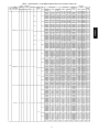
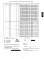
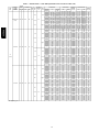
Table 1 — Electrical Data — Units Without Optional Powered Convenience Outlet (cont)
NOMINAL
POWER SUPPLY
VOLTS-PH-HZ
VOLTAGE
RANGE
MIN
MAX
COMPRESSOR
(EA.)
RLA
LRA
OFM
FLA
IFMF
LA
POWER
EXHAUST
FLA
2.0
ELECTRIC HEAT
IFM
TYPE
Low
07
(cont)
575-3-60
518
632
7.6
54.0
2.8
High
2.0
Low
0.8
1.4
2.9
High
5.2
Low
208/230-3-60
187
253
13.5
88
7.5
High
5.2
Low
1.5
3.0
7.5
High
2.6
Low
08
460-3-60
414
506
6.4
39
3.4
High
2.6
Low
0.8
1.2
3.4
High
Low
575-3-60
518
632
6.4
30.0
0.8
2.0
High
POWER SUPPLY
CRHEATER
PART NO.
FLA
NOMINAL
KW*
MCA
MOCP†
CRSINGLE
PART NO.
(NOTE3)
221A00
222A00
223A00
254A00
224A00
221A00
222A00
223A00
254A00
224A00
221A00
222A00
223A00
254A00
224A00
221A00
222A00
223A00
254A00
224A00
225A00
226A00
227A00
228A00
229A00
225A00
226A00
227A00
228A00
229A00
225A00
226A00
227A00
228A00
229A00
225A00
226A00
227A00
228A00
229A00
232A00
233A00
234A00
235A00
236A00
232A00
233A00
234A00
235A00
236A00
232A00
233A00
234A00
235A00
236A00
232A00
233A00
234A00
235A00
236A00
239A00
240A00
241A00
242A00
239A00
240A00
241A00
242A00
9.2
13.9
18.5
23.1
27.7
9.2
13.9
18.5
23.1
27.7
9.2
13.9
18.5
23.1
27.7
9.2
13.9
18.5
23.1
27.7
20.0/23.1
30.0/34.6
50.0/57.7
70.0/80.8
80.0/92.4
20.0/23.1
30.0/34.6
50.0/57.7
70.0/80.8
80.0/92.4
20.0/23.1
30.0/34.6
50.0/57.7
70.0/80.8
80.0/92.4
20.0/23.1
30.0/34.6
50.0/57.7
70.0/80.8
80.0/92.4
11.5
17.3
28.9
40.4
46.2
11.5
17.3
28.9
40.4
46.2
11.5
17.3
28.9
40.4
46.2
11.5
17.3
28.9
40.4
46.2
13.9
23.1
32.3
37.0
13.9
23.1
32.3
37.0
10.0
15.0
20.0
25.0
30.0
10.0
15.0
20.0
25.0
30.0
10.0
15.0
20.0
25.0
30.0
10.0
15.0
20.0
25.0
30.0
/
7.5/10.0
11.3/15.0
18.8/25.0
26.3/35.0
30.0/40.0
/
7.5/10.0
11.3/15.0
18.8/25.0
26.3/35.0
30.0/40.0
/
7.5/10.0
11.3/15.0
18.8/25.0
26.3/35.0
30.0/40.0
/
7.5/10.0
11.3/15.0
18.8/25.0
26.3/35.0
30.0/40.0
10.0
15.0
25.0
35.0
40.0
10.0
15.0
25.0
35.0
40.0
10.0
15.0
25.0
35.0
40.0
10.0
15.0
25.0
35.0
40.0
15.0
25.0
35.0
40.0
15.0
25.0
35.0
40.0
12.3
14.0
20.1
25.6
31.4
37.1
13.1
15.0
20.8
26.6
32.4
38.1
13.6
15.8
21.6
27.3
33.1
38.9
14.4
16.8
22.6
28.3
34.1
39.9
38.5/38.5
38.5/38.5
44.0/49.8
69.0/78.7
94.1/107.5
106.6/122.0
40.8/40.8
40.8/40.8
46.9/52.7
71.9/81.5
96.9/110.4
109.4/124.8
41.5/41.5
41.5/41.5
47.8/53.6
72.8/82.4
97.8/111.3
110.3/125.7
43.8/43.8
43.8/43.8
50.6/56.4
75.7/85.3
100.7/114.2
113.2/128.6
18.6
18.6
24.9
39.3
53.8
61.0
19.4
19.4
25.9
40.3
54.8
62.0
19.8
19.8
26.4
40.8
55.3
62.5
20.6
20.6
27.4
41.8
56.3
63.5
18.0
20.1
31.4
42.9
48.7
18.8
20.8
32.4
43.9
49.7
15
15
20
30
30
40
20
20
25
30
30
40
20
20
25
30
30
40
20
20
25
30
35
40
50/50
50/50
50/50
70/80
100/110
110/125
50/50
50/50
50/60
80/90
100/125
110/125
50/50
50/50
50/60
80/90
100/125
125/150
50/50
50/50
60/60
80/90
110/125
125/150
25
25
25
40
60
70
25
25
30
45
60
70
25
25
30
45
60
70
25
25
30
45
60
70
20
20
35
45
50
20
25
35
45
50
030A00
030A00
030A00
030A00
030A00
030A00
030A00
030A00
030A00
030A00
030A00
030A00
030A00
030A00
030A00
030A00
030A00
030A00
030A00
030A00
030A00
030A00
031A00
031A00
031A00
030A00
030A00
031A00
031A00
031A00
030A00
030A00
031A00
031A00
031A00
030A00
030A00
031A00
031A00
031A00
030A00
030A00
030A00
030A00
033A00
030A00
030A00
030A00
030A00
033A00
030A00
030A00
030A00
030A00
033A00
030A00
030A00
030A00
030A00
033A00
030A00
030A00
030A00
030A00
030A00
030A00
030A00
030A00
15
DISCONNECT SIZE
FLA
LRA
12
13
18
24
29
34
13
14
19
24
30
35
13
15
20
25
30
36
14
15
21
26
31
37
40/40
40/40
41/46
64/72
87/99
98/112
43/43
43/43
43/48
66/75
89/102
101/115
44/44
44/44
44/49
67/76
90/102
101/116
46/46
46/46
47/52
70/78
93/105
104/118
20
20
23
36
49
56
20
20
24
37
50
57
21
21
24
38
51
57
22
22
25
38
52
58
19
19
29
39
45
20
20
30
40
46
67
67
67
67
67
67
76
76
76
76
76
76
68
68
68
68
68
68
80
80
80
80
80
80
212/212
212/212
212/212
212/212
212/212
212/212
238/238
238/238
238/238
238/238
238/238
238/238
216/216
216/216
216/216
216/216
216/216
216/216
242/242
242/242
242/242
242/242
242/242
242/242
96
96
96
96
96
96
109
109
109
109
109
109
99
99
99
99
99
99
112
112
112
112
112
112
84
84
84
84
84
102
102
102
102
102
WIRING
FIG. NO.
15
15
15
15
15
15
15
15
15
15
15
15
15
15
15
15
15
15
15
15
15
15
16
17
17
15
15
16
17
17
15
15
16
17
17
15
15
16
17
17
15
15
15
15
19
15
15
15
15
19
15
15
15
15
19
15
15
15
15
19
15
15
15
15
15
15
15
15
50PG03−16
UNIT
50PG
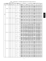
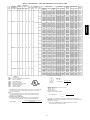
Table 1 — Electrical Data — Units Without Optional Powered Convenience Outlet (cont)
UNIT
50PG
NOMINAL
POWER SUPPLY
VOLTS-PH-HZ
VOLTAGE
RANGE
MIN
MAX
COMPRESSOR
(EA.)
RLA
LRA
OFM
IFM
FLA
FLA
POWER
EXHAUST
FLA
ELECTRIC HEAT
IFM
TYPE
Low
08
(cont)
575-3-60
(cont)
518
632
6.4
30.0
0.8
2.8
3.0
50PG03−16
High
Low
High
208/230-3-60
187
253
16.0
91
1.5
5.2
Low
09
3.0
High
2.6
460-3-60
414
506
7.1
46
0.8
Low
4.8
FLA
HACR
IFM
LRA
MCA
MOCP
NEC
OFM
RLA
−
−
−
−
−
−
−
−
−
High
FLA
NOMINAL
KW*
MCA
MOCP†
CRSINGLE
PART NO.
(NOTE3)
239A00
240A00
241A00
242A00
239A00
240A00
241A00
242A00
225A00
226A00
227A00
228A00
229A00
225A00
226A00
227A00
228A00
229A00
225A00
226A00
227A00
228A00
229A00
225A00
226A00
227A00
228A00
229A00
232A00
233A00
234A00
235A00
236A00
232A00
233A00
234A00
235A00
236A00
13.9
23.1
32.3
37.0
13.9
23.1
32.3
37.0
20.0/23.1
30.0/34.6
50.0/57.7
70.0/80.8
80.0/92.4
20.0/23.1
30.0/34.6
50.0/57.7
70.0/80.8
80.0/92.4
20.0/23.1
30.0/34.6
50.0/57.7
70.0/80.8
80.0/92.4
20.0/23.1
30.0/34.6
50.0/57.7
70.0/80.8
80.0/92.4
11.5
17.3
28.9
40.4
46.2
11.5
17.3
28.9
40.4
46.2
15.0
25.0
35.0
40.0
15.0
25.0
35.0
40.0
/
7.5/10.0
11.3/15.0
18.8/25.0
26.3/35.0
30.0/40.0
/
7.5/10.0
11.3/15.0
18.8/25.0
26.3/35.0
30.0/40.0
/
7.5/10.0
11.3/15.0
18.8/25.0
26.3/35.0
30.0/40.0
/
7.5/10.0
11.3/15.0
18.8/25.0
26.3/35.0
30.0/40.0
10.0
15.0
25.0
35.0
40.0
10.0
15.0
25.0
35.0
40.0
18.1
23.6
35.1
46.7
52.4
18.9
24.6
36.1
47.7
53.4
44.3/44.3
44.3/44.3
44.3/49.8
69.0/78.7
94.1/107.5
106.6/122.0
49.3/49.3
49.3/49.3
50.3/56.1
75.3/84.9
100.3/113.8
112.8/128.2
47.3/47.3
47.3/47.3
47.8/53.6
72.8/82.4
97.8/111.3
110.3/125.7
52.3/52.3
52.3/52.3
54.0/59.8
79.0/88.7
104.1/117.5
116.6/132.0
20.1
20.1
24.9
39.3
53.8
61.0
22.3
22.3
27.7
42.1
56.5
63.7
20
25
40
50
60
25
25
40
50
60
60/60
60/60
60/60
70/80
100/110
110/125
60/60
60/60
60/60
80/90
110/125
125/150
60/60
60/60
60/60
80/90
100/125
125/150
60/60
60/60
60/60
80/90
110/125
125/150
25
25
25
40
60
70
25
25
30
45
60
70
030A00
030A00
030A00
030A00
030A00
030A00
030A00
030A00
030A00
030A00
031A00
031A00
031A00
030A00
030A00
031A00
031A00
031A00
030A00
030A00
031A00
031A00
031A00
030A00
030A00
031A00
031A00
031A00
030A00
030A00
030A00
030A00
033A00
030A00
030A00
030A00
030A00
033A00
LEGEND
Full Load Amps
Heating, Air Conditioning and Refrigeration
Indoor − Fan Motor
Locked Rotor Amps
Minimum Circuit Amps
Maximum Overcurrent Protection
National Electrical Code
Outdoor−Fan Motor
Rated Load Amps
*
Heater capacity (kW) is based on heater voltage of 208 v, 240 v, or 480 v. If power distribution voltage to unit varies from rated heater voltage, heater kW will vary accordingly.
† Fuse or HACR circuit breaker.
NOTES:
1. In compliance with NEC requirements for multimotor and combination load equipment (refer to NEC Articles 430 and 440), the overcurrent protective device for the
unit shall be fuse or HACR breaker.
2. Unbalanced 3-Phase Supply Voltage
Never operate a motor where a phase imbalance in supply voltage is greater than
2%. Use the following formula to determine the percentage of voltage imbalance.
max voltage deviation from average voltage
% Voltage Imbalance
= 100 x
POWER SUPPLY
CRHEATER
PART NO.
DISCONNECT SIZE
FLA
LRA
19
22
32
43
48
20
23
33
44
49
46/46
46/46
46/46
64/72
87/99
98/112
52/52
52/52
52/52
69/78
92/105
104/118
50/50
50/50
50/50
67/76
90/102
101/116
55/55
55/55
55/55
73/82
96/108
107/121
21
21
23
36
49
56
24
24
25
39
52
59
86
86
86
86
86
98
98
98
98
98
218/218
218/218
218/218
218/218
218/218
218/218
261/261
261/261
261/261
261/261
261/261
261/261
222/222
222/222
222/222
222/222
222/222
222/222
265/265
265/265
265/265
265/265
265/265
265/265
110
110
110
110
110
110
132
132
132
132
132
132
WIRING
FIG. NO.
15
15
15
15
15
15
15
15
15
15
16
17
17
15
15
16
17
17
15
15
16
17
17
15
15
16
17
17
15
15
15
15
19
15
15
15
15
19
Example: Supply voltage is 460-3-60
AB = 224 v
BC = 231 v
AC = 226 v
Average Voltage =
=
=
224 + 231 + 226
3
681
3
227
Determine maximum deviation from average voltage.
(AB) 227 – 223 = 3 v
(BC) 231 – 227 = 4 v
(AC) 227 – 226 = 1 v
Maximum deviation is 4 v.
Determine percent of voltage imbalance.
4
% Voltage Imbalance
= 100 x
227
= 1.76%
This amount of phase imbalance is satisfactory as it is below the maximum allowable 2%.
IMPORTANT: If the supply voltage phase imbalance is more than 2%, contact your local electric
utility company immediately.
average voltage
3. Single point kits CRSINGLE028A00 and CRSINGLE030A00 are not required if
field−supplied pressure connectors are used.
16
Table 1 — Electrical Data — Units Without Optional Powered Convenience Outlet (cont)
NOMINAL
POWER SUPPLY
VOLTS-PH-HZ
VOLTAGE
RANGE
MIN
MAX
COMPRESSOR
(EA.)
RLA
LRA
OFM
IFM
FLA
FLA
POWER
EXHAUST
FLA
2.6
460-3-60
(cont)
414
506
7.1
46
0.8
ELECTRIC HEAT
IFM
TYPE
Low
1.2
4.8
High
2.0
Low
09
(cont)
575-3-60
518
632
5.6
37.0
3.3
High
2.0
Low
0.8
3.0
3.3
High
7.5
Low
208/230-3-60
187
253
17.6
123
10.2
High
7.5
Low
1.9
3.0
10.2
High
3.4
Low
12
460-3-60
414
506
7.7
50
4.8
High
3.4
Low
1.0
1.2
4.8
High
POWER SUPPLY
CRHEATER
PART NO.
FLA
NOMINAL
KW*
MCA
MOCP†
CRSINGLE
PART NO.
(NOTES)
232A00
233A00
234A00
235A00
236A00
232A00
233A00
234A00
235A00
236A00
239A00
240A00
241A00
242A00
239A00
240A00
241A00
242A00
239A00
240A00
241A00
242A00
239A00
240A00
241A00
242A00
225A00
226A00
227A00
228A00
229A00
230A00
225A00
226A00
227A00
228A00
229A00
230A00
225A00
226A00
227A00
228A00
229A00
230A00
225A00
226A00
227A00
228A00
229A00
230A00
232A00
233A00
234A00
235A00
236A00
237A00
232A00
233A00
234A00
235A00
236A00
237A00
232A00
233A00
234A00
235A00
236A00
237A00
232A00
233A00
234A00
235A00
236A00
237A00
11.5
17.3
28.9
40.4
46.2
11.5
17.3
28.9
40.4
46.2
13.9
23.1
32.3
37.0
13.9
23.1
32.3
37.0
13.9
23.1
32.3
37.0
13.9
23.1
32.3
37.0
20.0/23.1
30.0/34.6
50.0/57.7
70.0/80.8
80.0/92.4
100.1/115.5
20.0/23.1
30.0/34.6
50.0/57.7
70.0/80.8
80.0/92.4
100.1/115.5
20.0/23.1
30.0/34.6
50.0/57.7
70.0/80.8
80.0/92.4
100.1/115.5
20.0/23.1
30.0/34.6
50.0/57.7
70.0/80.8
80.0/92.4
100.1/115.5
11.5
17.3
28.9
40.4
46.2
57.7
11.5
17.3
28.9
40.4
46.2
57.7
11.5
17.3
28.9
40.4
46.2
57.7
11.5
17.3
28.9
40.4
46.2
57.7
10.0
15.0
25.0
35.0
40.0
10.0
15.0
25.0
35.0
40.0
15.0
25.0
35.0
40.0
15.0
25.0
35.0
40.0
15.0
25.0
35.0
40.0
15.0
25.0
35.0
40.0
/
7.5/10.0
11.3/15.0
18.8/25.0
26.3/35.0
30.0/40.0
37.6/50.0
/
7.5/10.0
11.3/15.0
18.8/25.0
26.3/35.0
30.0/40.0
37.6/50.0
/
7.5/10.0
11.3/15.0
18.8/25.0
26.3/35.0
30.0/40.0
37.6/50.0
/
7.5/10.0
11.3/15.0
18.8/25.0
26.3/35.0
30.0/40.0
37.6/50.0
10.0
15.0
25.0
35.0
40.0
50.0
10.0
15.0
25.0
35.0
40.0
50.0
10.0
15.0
25.0
35.0
40.0
50.0
10.0
15.0
25.0
35.0
40.0
50.0
21.3
21.3
26.4
40.8
55.3
62.5
23.5
23.5
29.2
43.6
58.0
65.2
16.2
20.1
31.4
42.9
48.7
17.5
21.4
33.0
45.1
50.3
19.1
23.6
35.1
46.7
52.4
19.9
24.6
36.1
47.7
53.4
51.0/51.0
51.0/51.0
51.0/52.7
71.9/81.5
96.9/110.4
109.4/124.8
134.5/124.8
53.7/53.7
53.7/53.7
53.7/56.1
75.3/84.9
100.3/113.8
112.8/128.2
137.8/128.2
54.0/54.0
54.0/54.0
54.0/56.4
75.7/85.3
100.7/114.2
113.2/128.6
138.2/128.6
56.7/56.7
56.7/56.7
56.7/59.8
79.0/88.7
104.1/117.5
116.6/132.0
141.6/132.0
22.7
22.7
25.9
40.3
54.8
62.0
62.0
24.1
24.1
27.7
42.1
56.5
63.7
63.7
23.9
23.9
27.4
41.8
56.3
63.5
63.5
25.3
25.3
29.2
43.6
58.0
65.2
65.2
25
25
30
45
60
70
30
30
30
45
60
70
20
20
35
45
50
20
25
35
45
50
25
25
40
50
60
25
25
40
50
60
60/60
60/60
60/60
80/90
100/125
110/125
150/150
60/60
60/60
60/60
80/90
110/125
125/150
150/150
60/60
60/60
60/60
80/90
110/125
125/150
150/150
70/70
70/70
70/70
80/90
110/125
125/150
150/150
30
30
30
45
60
70
70
30
30
30
45
60
70
70
30
30
30
45
60
70
70
30
30
30
45
60
70
70
030A00
030A00
030A00
030A00
033A00
030A00
030A00
030A00
030A00
033A00
030A00
030A00
030A00
030A00
030A00
030A00
030A00
030A00
030A00
030A00
030A00
030A00
030A00
030A00
030A00
030A00
030A00
030A00
031A00
031A00
031A00
031A00
030A00
030A00
031A00
031A00
031A00
031A00
030A00
030A00
031A00
031A00
031A00
031A00
030A00
030A00
031A00
031A00
031A00
031A00
030A00
030A00
030A00
030A00
033A00
033A00
030A00
030A00
030A00
030A00
033A00
033A00
030A00
030A00
030A00
030A00
033A00
033A00
030A00
030A00
030A00
030A00
033A00
033A00
17
DISCONNECT SIZE
FLA
LRA
22
22
24
38
51
57
25
25
27
40
53
60
17
18
29
39
45
19
20
30
41
46
20
22
32
43
48
21
23
33
44
49
54/54
54/54
54/54
66/75
89/102
101/115
124/141
57/57
57/57
57/57
69/78
92/105
104/118
127/145
57/57
57/57
57/57
70/78
93/105
104/118
127/145
60/60
60/60
60/60
73/82
96/108
107/121
130/148
24
24
24
37
50
57
70
26
26
26
39
52
59
72
25
25
25
38
52
58
72
27
27
27
40
53
60
73
113
113
113
113
113
113
134
134
134
134
134
134
98
98
98
98
98
136
136
136
136
136
92
92
92
92
92
104
104
104
104
104
314/314
314/314
314/314
314/314
314/314
314/314
314/314
331/331
331/331
331/331
331/331
331/331
331/331
331/331
318/318
318/318
318/318
318/318
318/318
318/318
318/318
335/335
335/335
335/335
335/335
335/335
335/335
335/335
130
130
130
130
130
130
130
139
139
139
139
139
139
139
133
133
133
133
133
133
133
141
141
141
141
141
141
141
WIRING
FIG. NO.
15
15
15
15
19
15
15
15
15
19
15
15
15
15
15
15
15
15
15
15
15
15
15
15
15
15
15
15
16
17
17
17
15
15
16
17
17
17
15
15
16
17
17
17
15
15
16
17
17
17
15
15
15
15
19
19
15
15
15
15
19
19
15
15
15
15
19
19
15
15
15
15
19
19
50PG03−16
UNIT
50PG
Table 1 — Electrical Data — Units Without Optional Powered Convenience Outlet (cont)
UNIT
50PG
NOMINAL
POWER SUPPLY
VOLTS-PH-HZ
VOLTAGE
RANGE
MIN
MAX
COMPRESSOR
(EA.)
RLA
LRA
OFM
FLA
IFM
FLA
POWER
EXHAUST
FLA
2.8
ELECTRIC HEAT
IFM
TYPE
Low
50PG03−16
12
(cont)
575-3-60
518 632
6.1
40.0
3.3
High
2.8
Low
0.8
3.0
3.3
FLA
HACR
IFM
LRA
MCA
MOCP
NEC
OFM
RLA
−
−
−
−
−
−
−
−
−
High
CRHEATER
PART NO.
FLA
NOMINAL
KW*
MCA
MOCP†
CRSINGLE
PART
NO.(NOTE3)
239A00
240A00
241A00
242A00
243A00
239A00
240A00
241A00
242A00
243A00
239A00
240A00
241A00
242A00
243A00
239A00
240A00
241A00
242A00
243A00
13.9
23.1
32.3
37.0
46.2
13.9
23.1
32.3
37.0
46.2
13.9
23.1
32.3
37.0
46.2
13.9
23.1
32.3
37.0
46.2
15.0
25.0
35.0
40.0
50.0
15.0
25.0
35.0
40.0
50.0
15.0
25.0
35.0
40.0
50.0
15.0
25.0
35.0
40.0
50.0
20.1
20.8
32.4
43.9
49.7
49.7
18.6
21.4
33.0
45.1
50.3
50.3
21.1
24.6
36.1
47.7
53.4
53.4
21.1
24.6
36.1
47.7
53.4
53.4
20
25
35
45
50
60
20
25
35
45
50
60
25
25
40
50
60
60
25
25
40
50
60
60
030A00
030A00
030A00
030A00
030A00
030A00
030A00
030A00
030A00
030A00
030A00
030A00
030A00
030A00
030A00
030A00
030A00
030A00
030A00
030A00
LEGEND
Full Load Amps
Heating, Air Conditioning and Refrigeration
Indoor − Fan Motor
Locked Rotor Amps
Minimum Circuit Amps
Maximum Overcurrent Protection
National Electrical Code
Outdoor−Fan Motor
Rated Load Amps
*
Heater capacity (kW) is based on heater voltage of 208 v, 240 v, or 480 v. If power distribution voltage to unit varies from rated heater voltage, heater kW will vary accordingly.
† Fuse or HACR circuit breaker.
NOTES:
1. In compliance with NEC requirements for multimotor and combination load equipment (refer to NEC Articles 430 and 440), the overcurrent protective device for the
unit shall be fuse or HACR breaker.
2. Unbalanced 3-Phase Supply Voltage
Never operate a motor where a phase imbalance in supply voltage is greater than
2%. Use the following formula to determine the percentage of voltage imbalance.
max voltage deviation from average voltage
% Voltage Imbalance
= 100 x
POWER SUPPLY
DISCONNECT
SIZE
FLA
LRA
21
21
32
42
48
58
20
20
30
41
46
57
23
23
33
44
49
60
23
23
33
44
49
60
124
124
124
124
124
124
142
142
142
142
142
142
110
110
110
110
110
110
110
110
110
110
110
110
WIRING
FIG. NO.
15
15
15
15
15
15
15
15
15
15
15
15
15
15
15
15
15
15
15
15
Example: Supply voltage is 460-3-60
AB = 224 v
BC = 231 v
AC = 226 v
Average Voltage =
=
=
224 + 231 + 226
3
681
3
227
Determine maximum deviation from average voltage.
(AB) 227 – 223 = 3 v
(BC) 231 – 227 = 4 v
(AC) 227 – 226 = 1 v
Maximum deviation is 4 v.
Determine percent of voltage imbalance.
4
% Voltage Imbalance
= 100 x
227
= 1.76%
This amount of phase imbalance is satisfactory as it is below the maximum allowable 2%.
IMPORTANT: If the supply voltage phase imbalance is more than 2%, contact your local electric
utility company immediately.
average voltage
3. Single point kits CRSINGLE028A00 and CRSINGLE030A00 are not required if
field−supplied pressure connectors are used.
18
Table 1 — Electrical Data — Units Without Optional Powered Convenience Outlet (cont)
NOMINAL
POWER SUPPLY
VOLTS-PH-HZ
VOLTAGE
RANGE
MIN
MAX
COMPRESSOR
(EA.)
RLA
LRA
OFM
FLA
IFM
FLA
POWER
EXHAUST
FLA
10.2
ELECTRIC HEAT
IFM
TYPE
Low
208/230-3-60
187 253
22.4
149
15.0
High
10.2
Low
1.9
3.0
15.0
High
4.8
Low
14
460-3-60
414 506
10.6
75
7.4
High
4.8
Low
1.0
1.2
7.4
High
3.3
Low
575-3-60
518 632
10.6
59.0
5.6
High
3.3
Low
0.8
3.0
5.6
High
POWER SUPPLY
CRHEATER
PART NO.
FLA
NOMINAL
KW*
MCA
MOCP†
CRSINGLE
PART
NO.(NOTE3)
225A00
226A00
227A00
228A00
230A00
231A00
225A00
226A00
227A00
228A00
230A00
231A00
225A00
226A00
227A00
228A00
230A00
231A00
225A00
226A00
227A00
228A00
230A00
231A00
232A00
233A00
234A00
235A00
237A00
238A00
232A00
233A00
234A00
235A00
237A00
238A00
232A00
233A00
234A00
235A00
237A00
238A00
232A00
233A00
234A00
235A00
237A00
238A00
239A00
240A00
241A00
242A00
243A00
244A00
239A00
240A00
241A00
242A00
243A00
244A00
239A00
240A00
241A00
242A00
243A00
244A00
239A00
240A00
241A00
242A00
243A00
244A00
20.0/23.1
30.0/34.6
50.0/57.7
70.0/80.8
100.1/115.5
120.1/138.6
20.0/23.1
30.0/34.6
50.0/57.7
70.0/80.8
100.1/115.5
120.1/138.6
20.0/23.1
30.0/34.6
50.0/57.7
70.0/80.8
100.1/115.5
120.1/138.6
20.0/23.1
30.0/34.6
50.0/57.7
70.0/80.8
100.1/115.5
120.1/138.6
11.5
17.3
28.9
40.4
57.7
69.3
11.5
17.3
28.9
40.4
57.7
69.3
11.5
17.3
28.9
40.4
57.7
69.3
11.5
17.3
28.9
40.4
57.7
69.3
13.9
23.1
32.3
37.0
46.2
55.4
13.9
23.1
32.3
37.0
46.2
55.4
13.9
23.1
32.3
37.0
46.2
55.4
13.9
23.1
32.3
37.0
46.2
55.4
/
7.5/10.0
11.3/15.0
18.8/25.0
26.3/35.0
37.6/50.0
45.1/60.0
/
7.5/10.0
11.3/15.0
18.8/25.0
26.3/35.0
37.6/50.0
45.1/60.0
/
7.5/10.0
11.3/15.0
18.8/25.0
26.3/35.0
37.6/50.0
45.1/60.0
/
7.5/10.0
11.3/15.0
18.8/25.0
26.3/35.0
37.6/50.0
45.1/60.0
10.0
15.0
25.0
35.0
50.0
60.0
10.0
15.0
25.0
35.0
50.0
60.0
10.0
15.0
25.0
35.0
50.0
60.0
10.0
15.0
25.0
35.0
50.0
60.0
15.0
25.0
35.0
40.0
50.0
60.0
15.0
25.0
35.0
40.0
50.0
60.0
15.0
25.0
35.0
40.0
50.0
60.0
13.9
23.1
32.3
37.0
46.2
55.4
64.5/64.5
64.5/64.5
64.5/64.5
75.3/84.9
100.3/113.8
137.8/128.2
162.8/151.3
69.3/69.3
69.3/69.3
69.3/69.3
81.3/90.9
106.3/119.8
143.8/134.2
168.8/157.3
67.5/67.5
67.5/67.5
67.5/67.5
79.0/88.7
104.1/117.5
141.6/132.0
166.6/155.1
72.3/72.3
72.3/72.3
72.3/72.3
85.0/94.7
110.1/123.5
147.6/138.0
172.6/161.1
30.6
30.6
30.6
42.1
56.5
63.7
75.3
33.2
33.2
33.2
45.3
59.8
67.0
78.5
31.8
31.8
31.8
43.6
58.0
65.2
76.8
34.4
34.4
34.4
46.8
61.3
68.5
80.0
28.7
28.7
33.0
45.1
50.3
50.3
59.6
31.0
31.0
35.9
47.4
53.2
53.2
62.4
24.7
24.7
36.1
47.7
53.4
53.4
62.7
27.5
28.1
39.6
51.2
56.9
56.9
66.2
80/80
80/80
80/80
80/90
110/125
150/150
175/175
90/90
90/90
90/90
90/100
110/125
150/150
175/175
80/80
80/80
80/80
80/90
110/125
150/150
175/175
90/90
90/90
90/90
90/100
125/125
150/150
175/175
40
40
40
45
60
70
90
40
40
40
50
60
80
90
40
40
40
45
60
70
90
45
45
45
50
70
80
90
25
25
35
45
50
60
60
30
30
40
50
60
60
70
30
30
40
50
60
60
70
30
30
40
60
60
60
70
032A00
032A00
032A00
032A00
032A00
032A00
032A00
032A00
032A00
032A00
032A00
032A00
032A00
032A00
032A00
032A00
032A00
032A00
032A00
032A00
032A00
032A00
032A00
032A00
030A00
030A00
030A00
030A00
033A00
033A00
030A00
030A00
030A00
030A00
033A00
033A00
030A00
030A00
030A00
030A00
033A00
033A00
030A00
030A00
030A00
033A00
033A00
033A00
030A00
030A00
030A00
030A00
030A00
030A00
030A00
030A00
030A00
030A00
030A00
033A00
030A00
030A00
030A00
030A00
030A00
033A00
030A00
030A00
030A00
030A00
030A00
033A00
19
DISCONNECT
SIZE
FLA
LRA
68/68
68/68
68/68
69/78
92/105
127/145
150/171
73/73
73/73
73/73
75/84
98/110
132/150
155/177
71/71
71/71
71/71
73/82
96/108
130/148
153/175
77/77
77/77
77/77
78/87
101/114
136/153
159/180
32
32
32
39
52
72
85
35
35
35
42
55
75
88
34
34
34
40
53
73
87
37
37
37
43
56
76
90
30
30
30
41
46
57
68
33
33
33
44
49
60
70
26
26
33
44
49
60
70
29
29
36
47
52
63
74
383/383
383/383
383/383
383/383
383/383
383/383
383/383
391/391
391/391
391/391
391/391
391/391
391/391
391/391
387/387
387/387
387/387
387/387
387/387
387/387
387/387
395/395
395/395
395/395
395/395
395/395
395/395
395/395
190
190
190
190
190
190
190
194
194
194
194
194
194
194
192
192
192
192
192
192
192
197
197
197
197
197
197
197
180
180
180
180
180
180
180
191
191
191
191
191
191
191
138
138
138
138
138
138
138
151
151
151
151
151
151
151
WIRING
FIG. NO.
18
18
18
18
18
18
18
18
18
18
18
18
18
18
18
18
18
18
18
18
18
18
18
18
15
15
15
15
19
19
15
15
15
15
19
19
15
15
15
15
19
19
15
15
15
15
19
19
15
15
15
15
15
15
15
15
15
15
15
19
15
15
15
15
15
19
15
15
15
15
15
19
50PG03−16
UNIT
50PG
Table 1 — Electrical Data — Units Without Optional Powered Convenience Outlet (cont)
UNIT
50PG
NOMINAL
POWER
SUPPLY
(V-PH-HZ)
VOLTAGE
RANGE
MIN
MAX
COMPR
NO. 1
RLA
LRA
COMPR
NO. 2
RLA
LRA
COMPR
NO. 3
RLA
LRA
OF
MFL
A
POWER
EXHAUST
QTY
FLA
ELECTRIC HEAT
IFM
TYPE
IFM
FLA
CRHEATER
PART NO.
Low
10.2
MidLow
15.0
50PG03−16
208/230-3-60
187
19.4
253 18.1 137 18.1 137 17.6 123 1.9
10.2
2
3.0
15.0
Low
MidLow
High
16
460-3-60
414
2
1.2
MidLow
High
Low
MidLow
High
518
4.8
7.4
9.7
506 9.0 62 9.0 62 7.7 50 1.0
Low
575-3-60
19.4
4.8
7.4
9.7
2.8
5.6
7.8
633 6.8 50 6.8 50 6.1 40 0.8
Low
2
3.0
MidLow
High
2.8
5.6
7.8
DISCONNECT SIZE
FLA
LRA
WIRING
FIG. NO.
80/80
482/482
80/81
482/482
20
256A00
104.2/120.3 37.6/50.0 143.0/133.0 150/150
034
132/150
482/482
20
257A00
156.3/180.4 56.3/75.0 169.1/193.2 200/225
034
192/219
482/482
20
79.0/79.0 90/90
86/86
491/491
255A00
52.1/60.1 18.8/25.0 83.9/93.9 90/100
034
86/86
491/491
20
256A00
104.2/120.3 37.6/50.0 149.0/139.0 150/175
034
137/156
491/491
20
257A00
156.3/180.4 56.3/75.0 175.1/199.2 200/225
034
197/225
491/491
20
83.4/83.4 100/100
91/91
529/529
255A00
52.1/60.1 18.8/25.0 89.4/99.4 100/100
034
91/91
529/529
20
256A00
104.2/120.3 37.6/50.0 154.5/144.5 175/175
034
142/161
529/529
20
257A00
156.3/180.4 56.3/75.0 180.6/204.7 200/225
034
202/230
529/529
20
77.2/77.2 90/90
84/84
486/486
255A00
52.1/60.1 18.8/25.0 81.6/91.7 90/100
034
84/84
486/486
20
256A00
104.2/120.3 37.6/50.0 146.8/136.8 150/150
034
135/154
486/486
20
257A00
156.3/180.4 56.3/75.0 172.8/196.9 200/225
034
195/223
486/486
20
82.0/82.0 100/100
89/89
495/495
255A00
52.1/60.1 18.8/25.0 87.6/97.7 100/100
034
89/90
495/495
20
256A00
104.2/120.3 37.6/50.0 152.8/142.8 175/175
034
141/159
495/495
20
257A00
156.3/180.4 56.3/75.0 178.8/202.9 200/225
034
200/228
495/495
20
86.4/86.4 100/100
94/94
533/533
255A00
52.1/60.1 18.8/25.0 93.1/103.2 100/110
034
94/95
533/533
20
256A00
104.2/120.3 37.6/50.0 158.3/148.3 175/175
034
146/164
533/533
20
257A00
156.3/180.4 56.3/75.0 184.3/208.4 200/250
034
206/233
533/533
20
High
CRSINGLE
PART NO.
(NOTE3)
034
MidLow
/
MOCP
74.2/74.2 90/90
Low
MCA
52.1/60.1 18.8/25.0 77.9/87.9 90/90
High
NOMINAL
KW*
255A00
POWER SUPPLY
FLA
/
/
/
/
/
/
35.8
40
39
215
258A00
30.1
25.0
43.6
45
035
40
215
21
259A00
60.1
50.0
66.1
80
036
75
215
22
260A00
90.2
75.0
96.2
100
036
109
215
22
/
38.4
45
42
219
258A00
30.1
25.0
46.8
50
035
43
219
21
259A00
60.1
50.0
69.4
80
036
78
219
22
260A00
90.2
75.0
99.5
110
036
112
219
22
/
40.7
50
44
238
258A00
30.1
25.0
49.7
50
035
46
238
21
259A00
60.1
50.0
72.3
80
036
80
238
22
260A00
90.2
75.0
102.3
125
036
115
238
22
/
37.0
45
40
217
258A00
30.1
25.0
45.1
50
035
41
217
21
259A00
60.1
50.0
67.6
80
036
76
217
22
260A00
90.2
75.0
97.7
100
036
111
217
22
/
39.6
45
43
222
258A00
30.1
25.0
48.3
50
035
44
222
21
259A00
60.1
50.0
70.9
80
036
79
222
22
260A00
90.2
75.0
101.0
110
036
114
222
22
/
41.9
50
46
241
258A00
30.1
25.0
51.2
60
036
47
241
21
259A00
60.1
50.0
73.8
80
036
82
241
22
260A00
90.2
75.0
103.8
125
036
116
241
22
/
26.6
30
29
167
261A00
24.1
25.0
33.6
35
035
31
167
21
262A00
46.2
50.0
49.7
60
035
56
167
21
263A00
72.2
75.0
75.7
80
036
86
167
22
/
29.4
35
32
181
261A00
24.1
25.0
37.1
40
035
34
181
21
262A00
46.2
50.0
53.2
60
035
60
181
21
263A00
72.2
75.0
79.2
90
036
89
181
22
/
31.6
35
34
196
261A00
24.1
25.0
39.8
40
035
37
196
21
262A00
46.2
50.0
55.9
60
035
62
196
21
263A00
72.2
75.0
81.9
90
036
92
196
22
/
29.6
35
32
171
261A00
24.1
25.0
37.3
40
035
34
171
21
262A00
46.2
50.0
53.4
60
035
60
171
21
263A00
72.2
75.0
79.4
90
036
90
171
22
/
32.4
35
35
185
261A00
24.1
25.0
40.8
45
035
38
185
21
262A00
46.2
50.0
56.9
60
035
63
185
21
263A00
72.2
75.0
82.9
90
036
93
185
22
/
34.6
40
38
200
261A00
24.1
25.0
43.6
45
035
40
200
21
262A00
46.2
50.0
59.7
70
035
66
200
21
263A00
72.2
75.0
85.7
100
036
95
200
22
20
Table 2 — Electrical Data — Units With Optional Powered Convenience Outlet
NOMINAL
POWER SUPPLY
VOLTS-PH-HZ
VOLTAGE
RANGE
MIN
MA
X
COMPRESSOR
(EA)
RLA
LRA
OFM
FLA
IFM
FLA
POWER
EXHAUST
FLA
ELECTRIC HEAT
IFM
TYPE
Low
High
03
208/230-1-60
187 253
12.8
60
0.9
4.9
Low
1.4
High
Low
High
208/230-1-60
187 253
15.4
83
0.9
4.9
Low
04
1.4
High
Low
208/230-3-60
187 253
11.5
77
0.9
4.9
High
FLA
HACR
IFM
LRA
MCA
MOCP
NEC
OFM
RLA
−
−
−
−
−
−
−
−
−
LEGEND
Full Load Amps
Heating, Air Conditioning and Refrigeration
Indoor − Fan Motor
Locked Rotor Amps
Minimum Circuit Amps
Maximum Overcurrent Protection
National Electrical Code
Outdoor−Fan Motor
Rated Load Amps
*
Heater capacity (kW) is based on heater voltage of 208 v, 240 v, or 480 v. If power distribution voltage to unit varies from rated heater voltage, heater kW will vary accordingly.
† Fuse or HACR circuit breaker.
NOTES:
1. In compliance with NEC requirements for multimotor and combination load equipment (refer to NEC Articles 430 and 440), the overcurrent protective device for the
unit shall be fuse or HACR breaker.
2. Unbalanced 3-Phase Supply Voltage
Never operate a motor where a phase imbalance in supply voltage is greater than
2%. Use the following formula to determine the percentage of voltage imbalance.
max voltage deviation from average voltage
% Voltage Imbalance
= 100 x
POWER SUPPLY
CRHEATER
PART NO.
FLA
NOMINAL
KW*
MCA
MOCP†
CRSINGLE
PART NO.
(NOTE3)
200A00
201A00
202A00
203A00
200A00
201A00
202A00
203A00
200A00
201A00
202A00
203A00
200A00
201A00
202A00
203A00
200A00
201A00
202A00
203A00
204A00
200A00
201A00
202A00
203A00
204A00
200A00
201A00
202A00
203A00
204A00
200A00
201A00
202A00
203A00
204A00
207A00
208A00
209A00
210A00
211A00
207A00
208A00
209A00
210A00
211A00
10.8/12.5
17.3/20.0
26.0/30.0
34.7/40.0
10.8/12.5
17.3/20.0
26.0/30.0
34.7/40.0
10.8/12.5
17.3/20.0
26.0/30.0
34.7/40.0
10.8/12.5
17.3/20.0
26.0/30.0
34.7/40.0
10.8/12.5
17.3/20.0
26.0/30.0
34.7/40.0
52.0/60.0
10.8/12.5
17.3/20.0
26.0/30.0
34.7/40.0
52.0/60.0
10.8/12.5
17.3/20.0
26.0/30.0
34.7/40.0
52.0/60.0
10.8/12.5
17.3/20.0
26.0/30.0
34.7/40.0
52.0/60.0
6.3/7.2
10.0/11.5
15.0/17.3
20.0/23.1
30.0/34.6
6.3/7.2
10.0/11.5
15.0/17.3
20.0/23.1
30.0/34.6
/
2.3/3.0
3.8/5.0
5.6/7.5
7.5/10.0
/
2.3/3.0
3.8/5.0
5.6/7.5
7.5/10.0
/
2.3/3.0
3.8/5.0
5.6/7.5
7.5/10.0
/
2.3/3.0
3.8/5.0
5.6/7.5
7.5/10.0
/
2.3/3.0
3.8/5.0
5.6/7.5
7.5/10.0
11.3/15.0
/
2.3/3.0
3.8/5.0
5.6/7.5
7.5/10.0
11.3/15.0
/
2.3/3.0
3.8/5.0
5.6/7.5
7.5/10.0
11.3/15.0
/
2.3/3.0
3.8/5.0
5.6/7.5
7.5/10.0
11.3/15.0
/
2.3/3.0
3.8/5.0
5.6/7.5
7.5/10.0
11.3/15.0
/
2.3/3.0
3.8/5.0
5.6/7.5
7.5/10.0
11.3/15.0
27.8/27.8
27.8/27.8
32.8/36.1
43.6/48.6
54.5/61.1
27.8/27.8
27.8/27.8
32.8/36.1
43.6/48.6
54.5/61.1
29.2/29.2
29.2/29.2
34.5/37.9
45.4/50.4
56.2/62.9
29.2/29.2
29.2/29.2
34.5/37.9
45.4/50.4
56.2/62.9
31.0/31.0
31.0/31.0
32.8/36.1
43.6/48.6
54.5/61.1
76.1/86.1
31.0/31.0
31.0/31.0
32.8/36.1
43.6/48.6
54.5/61.1
76.1/86.1
32.4/32.4
32.4/32.4
34.5/37.9
45.4/50.4
56.2/62.9
77.9/87.9
32.4/32.4
32.4/32.4
34.5/37.9
45.4/50.4
56.2/62.9
77.9/87.9
25.0/25.0
25.0/25.0
25.0/26.0
30.9/33.2
37.2/40.4
49.7/54.9
25.0/25.0
25.0/25.0
25.0/26.0
30.9/33.2
37.2/40.4
49.7/54.9
30/30
30/30
35/40
45/50
60/70
30/30
30/30
35/40
45/50
60/70
40/40
40/40
40/40
50/60
60/70
40/40
40/40
40/40
50/60
60/70
45/45
45/45
45/45
45/50
60/70
80/90
45/45
45/45
45/45
45/50
60/70
80/90
45/45
45/45
45/45
50/60
60/70
80/90
45/45
45/45
45/45
50/60
60/70
80/90
30/30
30/30
30/30
35/35
40/45
50/60
30/30
30/30
30/30
35/35
40/45
50/60
028A00
028A00
028A00
028A00
028A00
028A00
028A00
028A00
028A00
028A00
028A00
028A00
028A00
028A00
028A00
028A00
028A00
028A00
028A00
028A00
029A00
028A00
028A00
028A00
028A00
029A00
028A00
028A00
028A00
028A00
029A00
028A00
028A00
028A00
028A00
029A00
030A00
030A00
030A00
030A00
030A00
030A00
030A00
030A00
030A00
030A00
DISCONNECT SIZE
FLA
LRA
27/27
27/27
31/34
41/46
51/57
27/27
27/27
31/34
41/46
51/57
29/29
29/29
33/36
43/47
53/59
29/29
29/29
33/36
43/47
53/59
30/30
30/30
31/34
41/46
51/57
71/80
30/30
30/30
31/34
41/46
51/57
71/80
32/32
32/32
33/36
43/47
53/59
73/82
32/32
32/32
33/36
43/47
53/59
73/82
25/25
25/25
25/25
28/31
34/38
46/51
25/25
25/25
25/25
28/31
34/38
46/51
78/78
78/78
78/78
78/78
78/78
78/78
78/78
78/78
78/78
78/78
80/80
80/80
80/80
80/80
80/80
80/80
80/80
80/80
80/80
80/80
101/101
101/101
101/101
101/101
101/101
101/101
101/101
101/101
101/101
101/101
101/101
101/101
103/103
103/103
103/103
103/103
103/103
103/103
103/103
103/103
103/103
103/103
103/103
103/103
95/95
95/95
95/95
95/95
95/95
95/95
95/95
95/95
95/95
95/95
95/95
95/95
WIRING
FIG. NO.
13
13
13
13
13
13
13
13
13
13
13
13
13
13
13
13
13
13
13
13
14
13
13
13
13
14
13
13
13
13
14
13
13
13
13
14
15
15
15
15
15
15
15
15
15
15
Example: Supply voltage is 460-3-60
AB = 224 v
BC = 231 v
AC = 226 v
Average Voltage =
=
=
224 + 231 + 226
3
681
3
227
Determine maximum deviation from average voltage.
(AB) 227 – 223 = 3 v
(BC) 231 – 227 = 4 v
(AC) 227 – 226 = 1 v
Maximum deviation is 4 v.
Determine percent of voltage imbalance.
4
% Voltage Imbalance
= 100 x
227
= 1.76%
This amount of phase imbalance is satisfactory as it is below the maximum allowable 2%.
IMPORTANT: If the supply voltage phase imbalance is more than 2%, contact your local electric
utility company immediately.
average voltage
3. Single point kits CRSINGLE028A00 and CRSINGLE030A00 are not required if
field−supplied pressure connectors are used.
21
50PG03−16
UNIT
50PG
Table 2 — Electrical Data — Units With Optional Powered Convenience Outlet (cont)
UNIT
50PG
NOMINAL
POWER
SUPPLY
VOLTS-PH-HZ
VOLTAGE
RANGE
MIN
MAX
COMPRESSOR
(EA)
RLA
LRA
OFM
FLA
IFM
FLA
POWER
EXHAUST
FLA
ELECTRIC HEATC
IFM
TYPE
Low
208/230-3-60
(cont)
187
253
11.5
77
0.9
4.9
1.4
50PG03−16
High
Low
High
04
460-3-60
414
506
5.1
35
0.5
2.1
Low
0.6
High
Low
High
575-3-60
518
632
4.3
31.0
0.4
2.2
Low
1.4
High
4.9
Low
208/230-1-60
187
253
20.5
109
7.0
High
4.9
Low
0.9
05
1.4
208/230-3-60
187
253
14.6
91
7.0
High
4.9
Low
0.9
5.2
High
POWER SUPPLY
CRHEATER
PART NO.
FLA
NOMINAL
KW*
MCA
MOCP†
CRSINGLE
PART NO.
(NOTE3)
207A00
208A00
209A00
210A00
211A00
207A00
208A00
209A00
210A00
211A00
214A00
215A00
216A00
217A00
218A00
214A00
215A00
216A00
217A00
218A00
214A00
215A00
216A00
217A00
218A00
214A00
215A00
216A00
217A00
218A00
221A00
222A00
221A00
222A00
221A00
222A00
221A00
222A00
201A00
202A00
203A00
204A00
205A00
201A00
202A00
203A00
204A00
205A00
201A00
202A00
203A00
204A00
205A00
201A00
202A00
203A00
204A00
205A00
208A00
209A00
210A00
211A00
212A00
208A00
209A00
210A00
211A00
212A00
6.3/7.2
10.0/11.5
15.0/17.3
20.0/23.1
30.0/34.6
6.3/7.2
10.0/11.5
15.0/17.3
20.0/23.1
30.0/34.6
3.5
5.8
8.7
11.5
17.3
3.5
5.8
8.7
11.5
17.3
3.5
5.8
8.7
11.5
17.3
3.5
5.8
8.7
11.5
17.3
9.2
13.9
9.2
13.9
9.2
13.9
9.2
13.9
17.3/20.0
26.0/30.0
34.7/40.0
52.0/60.0
69.3/80.0
17.3/20.0
26.0/30.0
34.7/40.0
52.0/60.0
69.3/80.0
17.3/20.0
26.0/30.0
34.7/40.0
52.0/60.0
69.3/80.0
17.3/20.0
26.0/30.0
34.7/40.0
52.0/60.0
69.3/80.0
10.0/11.5
15.0/17.3
20.0/23.1
30.0/34.6
40.0/46.2
10.0/11.5
15.0/17.3
20.0/23.1
30.0/34.6
40.0/46.2
/
2.3/3.0
3.8/5.0
5.6/7.5
7.5/10.0
11.3/15.0
/
2.3/3.0
3.8/5.0
5.6/7.5
7.5/10.0
11.3/15.0
3.0
5.0
7.5
10.0
15.0
3.0
5.0
7.5
10.0
15.0
3.0
5.0
7.5
10.0
15.0
3.0
5.0
7.5
10.0
15.0
10.0
15.0
10.0
15.0
10.0
15.0
10.0
15.0
/
3.8/5.0
5.6/7.5
7.5/10.0
11.3/15.0
15.0/20.0
/
3.8/5.0
5.6/7.5
7.5/10.0
11.3/15.0
15.0/20.0
/
3.8/5.0
5.6/7.5
7.5/10.0
11.3/15.0
15.0/20.0
/
3.8/5.0
5.6/7.5
7.5/10.0
11.3/15.0
15.0/20.0
/
3.8/5.0
5.6/7.5
7.5/10.0
11.3/15.0
15.0/20.0
/
3.8/5.0
5.6/7.5
7.5/10.0
11.3/15.0
15.0/20.0
26.4/26.4
26.4/26.4
26.4/27.7
32.6/35.0
38.9/42.2
51.4/56.6
26.4/26.4
26.4/26.4
26.4/27.7
32.6/35.0
38.9/42.2
51.4/56.6
11.2
11.2
12.6
16.2
19.8
27.0
11.2
11.2
12.6
16.2
19.8
27.0
11.8
11.8
13.3
16.9
20.5
27.7
11.8
11.8
13.3
16.9
20.5
27.7
9.7
16.3
22.1
9.7
16.3
22.1
11.1
18.0
23.9
11.1
18.0
23.9
37.4/37.4
37.4/37.4
43.6/48.6
54.5/61.1
76.1/86.1
97.8/111.1
39.5/39.5
39.5/39.5
46.2/51.3
57.1/63.8
78.7/88.8
100.4/113.8
38.8/38.8
38.8/38.8
45.4/50.4
56.2/62.9
77.9/87.9
99.5/112.9
40.9/40.9
40.9/40.9
48.0/53.0
58.8/65.5
80.5/90.5
102.2/115.5
28.8/28.8
28.8/28.8
30.9/33.2
37.2/40.4
49.7/54.9
62.2/69.3
29.1/29.1
29.1/29.1
31.3/33.6
37.5/40.8
50.0/55.2
62.5/69.7
30/30
30/30
30/30
35/40
40/45
60/60
30/30
30/30
30/30
35/40
40/45
60/60
15
15
15
20
20
30
15
15
15
20
20
30
15
15
15
20
25
30
15
15
15
20
25
30
15
20
25
15
20
25
15
20
25
15
20
25
50/50
50/50
50/50
60/70
80/90
100/125
50/50
50/50
50/60
60/70
80/90
110/125
50/50
50/50
50/60
60/70
80/90
110/125
60/60
60/60
60/60
60/70
90/100
110/125
40/40
40/40
40/40
40/45
50/60
70/70
40/40
40/40
40/40
40/45
60/60
70/80
030A00
030A00
030A00
030A00
030A00
030A00
030A00
030A00
030A00
030A00
030A00
030A00
030A00
030A00
030A00
030A00
030A00
030A00
030A00
030A00
030A00
030A00
030A00
030A00
030A00
030A00
030A00
030A00
030A00
030A00
030A00
030A00
030A00
030A00
030A00
030A00
030A00
030A00
028A00
028A00
028A00
029A00
029A00
028A00
028A00
028A00
029A00
029A00
028A00
028A00
028A00
029A00
029A00
028A00
028A00
028A00
029A00
029A00
030A00
030A00
030A00
030A00
031A00
030A00
030A00
030A00
030A00
031A00
22
DISCONNECT SIZE
FLA
LRA
27/27
27/27
27/27
30/33
36/39
47/53
27/27
27/27
27/27
30/33
36/39
47/53
11
11
12
15
18
25
11
11
12
15
18
25
12
12
12
16
19
26
12
12
12
16
19
26
10
15
20
10
15
20
12
17
22
12
17
22
36/36
36/36
41/46
51/57
71/80
91/103
38/38
38/38
43/48
53/60
73/83
93/106
37/37
37/37
43/47
53/59
73/82
92/105
40/40
40/40
45/50
55/61
75/84
95/107
29/29
29/29
29/31
34/38
46/51
57/64
29/29
29/29
29/31
35/38
46/51
58/65
97/97
97/97
97/97
97/97
97/97
97/97
97/97
97/97
97/97
97/97
97/97
97/97
44
44
44
44
44
44
44
44
44
44
44
44
45
45
45
45
45
45
45
45
45
45
45
45
39
39
38
39
39
39
41
41
41
41
41
41
127/127
127/127
127/127
127/127
127/127
127/127
153/153
153/153
153/153
153/153
153/153
153/153
129/129
129/129
129/129
129/129
129/129
129/129
155/155
155/155
155/155
155/155
155/155
155/155
109/109
109/109
109/109
109/109
109/109
109/109
128/128
128/128
128/128
128/128
128/128
128/128
WIRING
FIG. NO.
15
15
15
15
15
15
15
15
15
15
15
15
15
15
15
15
15
15
15
15
15
15
15
15
15
15
15
15
15
15
15
15
15
15
15
15
15
15
13
13
13
14
14
13
13
13
14
14
13
13
13
14
14
13
13
13
14
14
15
15
15
15
16
15
15
15
15
16
Table 2 — Electrical Data — Units With Optional Powered Convenience Outlet (cont)
MIN
MAX
COMPRESSOR
(EA)
RLA
LRA
OFM
FLA
IFM
FLA
POWER
EXHAUST
FLA
4.9
208/230-3-60
(cont)
187
253
14.6
91
0.9
IFM
TYPE
Low
1.4
5.2
High
2.1
Low
460-3-60
414
506
7.1
46
2.6
High
2.1
Low
0.5
05
(cont)
0.6
2.6
High
Low
High
575-3-60
518
632
5.0
34.0
0.4
2.0
Low
1.4
High
4.9
06
208/230-1-60
187
253
26.9
145
1.5
Low
7.0
FLA
HACR
IFM
LRA
MCA
MOCP
NEC
OFM
RLA
−
−
−
−
−
−
−
−
−
High
ELECTRIC HEAT
CRHEATER
PART NO.
208A00
209A00
210A00
211A00
212A00
208A00
209A00
210A00
211A00
212A00
215A00
216A00
217A00
218A00
219A00
215A00
216A00
217A00
218A00
219A00
215A00
216A00
217A00
218A00
219A00
215A00
216A00
217A00
218A00
219A00
221A00
222A00
223A00
221A00
222A00
223A00
221A00
222A00
223A00
221A00
222A00
223A00
201A00
202A00
203A00
204A00
205A00
206A00
201A00
202A00
203A00
204A00
205A00
206A00
LEGEND
Full Load Amps
Heating, Air Conditioning and Refrigeration
Indoor − Fan Motor
Locked Rotor Amps
Minimum Circuit Amps
Maximum Overcurrent Protection
National Electrical Code
Outdoor−Fan Motor
Rated Load Amps
*
Heater capacity (kW) is based on heater voltage of 208 v, 240 v, or 480 v. If power distribution voltage to unit varies from rated heater voltage, heater kW will vary accordingly.
† Fuse or HACR circuit breaker.
NOTES:
1. In compliance with NEC requirements for multimotor and combination load equipment (refer to NEC Articles 430 and 440), the overcurrent protective device for the
unit shall be fuse or HACR breaker.
2. Unbalanced 3-Phase Supply Voltage
Never operate a motor where a phase imbalance in supply voltage is greater than
2%. Use the following formula to determine the percentage of voltage imbalance.
max voltage deviation from average voltage
% Voltage Imbalance
POWER SUPPLY
FLA
NOMINAL
KW*
MCA
MOCP†
CRSINGLE
PART NO.
(NOTE3)
10.0/11.5
15.0/17.3
20.0/23.1
30.0/34.6
40.0/46.2
10.0/11.5
15.0/17.3
20.0/23.1
30.0/34.6
40.0/46.2
5.8
8.7
11.5
17.3
23.1
5.8
8.7
11.5
17.3
23.1
5.8
8.7
11.5
17.3
23.1
5.8
8.7
11.5
17.3
23.1
9.2
13.9
18.5
9.2
13.9
18.5
9.2
13.9
18.5
9.2
13.9
18.5
17.3/20.0
26.0/30.0
34.7/40.0
52.0/60.0
69.3/80.0
86.7/100.0
17.3/20.0
26.0/30.0
34.7/40.0
52.0/60.0
69.3/80.0
86.7/100.0
/
3.8/5.0
5.6/7.5
7.5/10.0
11.3/15.0
15.0/20.0
/
3.8/5.0
5.6/7.5
7.5/10.0
11.3/15.0
15.0/20.0
5.0
7.5
10.0
15.0
20.0
5.0
7.5
10.0
15.0
20.0
5.0
7.5
10.0
15.0
20.0
5.0
7.5
10.0
15.0
20.0
10.0
15.0
20.0
10.0
15.0
20.0
10.0
15.0
20.0
10.0
15.0
20.0
/
3.8/5.0
5.6/7.5
7.5/10.0
11.3/15.0
15.0/20.0
18.8/25.0
/
3.8/5.0
5.6/7.5
7.5/10.0
11.3/15.0
15.0/20.0
18.8/25.0
30.2/30.2
30.2/30.2
32.6/35.0
38.9/42.2
51.4/56.6
63.9/71.0
30.5/30.5
30.5/30.5
33.0/35.3
39.3/42.6
51.8/57.0
64.3/71.4
13.6
13.6
16.2
19.8
27.0
34.2
14.1
14.1
16.8
20.4
27.6
34.8
14.2
14.2
16.9
20.5
27.7
35.0
14.7
14.7
17.5
21.2
28.4
35.6
10.7
16.3
22.1
27.9
10.6
16.1
22.0
27.8
12.1
18.0
23.9
29.6
12.0
17.9
23.8
29.5
46.1/46.1
46.1/46.1
46.1/48.6
54.5/61.1
76.1/86.1
97.8/111.1
119.4/136.1
48.2/48.2
48.2/48.2
48.2/51.3
57.1/63.8
78.7/88.8
100.4/113.8
122.1/138.8
40/40
40/40
40/40
40/45
60/60
70/80
45/45
45/45
45/45
45/45
60/60
70/80
20
20
20
20
30
35
20
20
20
25
30
35
20
20
20
25
30
40
20
20
20
25
30
40
15
20
25
30
15
20
25
30
15
20
25
30
15
20
25
30
60/60
60/60
60/60
60/70
80/90
100/125
125/150
60/60
60/60
60/60
60/70
80/90
110/125
125/150
030A00
030A00
030A00
030A00
031A00
030A00
030A00
030A00
030A00
031A00
030A00
030A00
030A00
030A00
030A00
030A00
030A00
030A00
030A00
030A00
030A00
030A00
030A00
030A00
030A00
030A00
030A00
030A00
030A00
030A00
030A00
030A00
030A00
030A00
030A00
030A00
030A00
030A00
030A00
030A00
030A00
030A00
028A00
028A00
028A00
029A00
029A00
029A00
028A00
028A00
028A00
029A00
029A00
029A00
DISCONNECT SIZE
FLA
LRA
31/31
31/31
31/33
36/39
47/53
59/66
31/31
31/31
31/33
36/40
48/53
59/66
14
14
15
18
25
31
14
14
15
19
25
32
14
14
16
19
26
32
15
15
16
19
26
33
11
15
20
26
11
15
20
26
12
17
22
27
12
16
22
27
44/44
44/44
44/46
51/57
71/80
91/103
111/126
46/46
46/46
46/48
53/60
73/83
93/106
113/129
111/111
111/111
111/111
111/111
111/111
111/111
130/130
130/130
130/130
130/130
130/130
130/130
55
55
55
55
55
55
64
64
64
64
64
64
56
56
56
56
56
56
65
65
65
65
65
65
42
42
42
42
48
48
48
48
44
44
44
44
50
50
50
50
164/164
164/164
164/164
164/164
164/164
164/164
164/164
190/190
190/190
190/190
190/190
190/190
190/190
190/190
WIRING
FIG. NO.
15
15
15
15
16
15
15
15
15
16
15
15
15
15
15
15
15
15
15
15
15
15
15
15
15
15
15
15
15
15
15
15
15
15
15
15
15
15
15
15
15
15
13
13
13
14
14
14
13
13
13
14
14
14
Example: Supply voltage is 460-3-60
AB = 224 v
BC = 231 v
AC = 226 v
Average Voltage =
=
=
224 + 231 + 226
3
681
3
227
Determine maximum deviation from average voltage.
(AB) 227 – 223 = 3 v
(BC) 231 – 227 = 4 v
(AC) 227 – 226 = 1 v
Maximum deviation is 4 v.
Determine percent of voltage imbalance.
4
% Voltage Imbalance
= 100 x
227
= 1.76%
This amount of phase imbalance is satisfactory as it is below the maximum allowable 2%.
IMPORTANT: If the supply voltage phase imbalance is more than 2%, contact your local electric
utility company immediately.
= 100 x
3. Single point kits CRSINGLE028A00 and CRSINGLE030A00 are not required if
field−supplied pressure connectors are used.
average voltage
23
50PG03−16
NOMINAL
POWER
SUPPLY
VOLTS-PH-HZ
UNIT
50PG
VOLTAGE
RANGE
Table 2 — Electrical Data — Units With Optional Powered Convenience Outlet (cont)
UNIT
50PG
NOMINAL
POWER SUPPLY
VOLTS-PH-HZ
VOLTAGE
RANGE
MIN
MAX
COMPRESSOR
RLA
LRA
OFM
FLA
IFM
FLA
POWER
EXHAUST
FLA
4.9
208/230-1-60
(cont)
187
253
26.9
145
1.5
ELECTRIC HEAT
IFM
TYPE
Low
1.4
High
50PG03−16
7.0
Low
High
208/230-3-60
187
253
17.6
123
1.5
5.2
Low
1.4
High
06
(cont)
Low
High
460-3-60
414
506
7.7
50
0.8
2.6
Low
0.6
High
Low
High
575-3-60
518
632
6.1
40.0
0.8
2.0
Low
1.4
High
POWER SUPPLY
DISCONNECT SIZE
CRHEATER
PART NO.
FLA
NOMINAL
KW*
MCA
MOCP†
CRSINGLE
PART NO.
(NOTE3)
FLA
LRA
201A00
202A00
203A00
204A00
205A00
206A00
201A00
202A00
203A00
204A00
205A00
206A00
208A00
209A00
210A00
211A00
212A00
213A00
208A00
209A00
210A00
211A00
212A00
213A00
208A00
209A00
210A00
211A00
212A00
213A00
208A00
209A00
210A00
211A00
212A00
213A00
215A00
216A00
217A00
218A00
219A00
220A00
215A00
216A00
217A00
218A00
219A00
220A00
215A00
216A00
217A00
218A00
219A00
220A00
215A00
216A00
217A00
218A00
219A00
220A00
221A00
222A00
223A00
254A00
221A00
222A00
223A00
254A00
221A00
222A00
223A00
254A00
221A00
222A00
223A00
254A00
17.3/20.0
26.0/30.0
34.7/40.0
52.0/60.0
69.3/80.0
86.7/100.0
17.3/20.0
26.0/30.0
34.7/40.0
52.0/60.0
69.3/80.0
86.7/100.0
10.0/11.5
15.0/17.3
20.0/23.1
30.0/34.6
40.0/46.2
50.0/57.7
10.0/11.5
15.0/17.3
20.0/23.1
30.0/34.6
40.0/46.2
50.0/57.7
10.0/11.5
15.0/17.3
20.0/23.1
30.0/34.6
40.0/46.2
50.0/57.7
10.0/11.5
15.0/17.3
20.0/23.1
30.0/34.6
40.0/46.2
50.0/57.7
5.8
8.7
11.5
17.3
23.1
28.9
5.8
8.7
11.5
17.3
23.1
28.9
5.8
8.7
11.5
17.3
23.1
28.9
5.8
8.7
11.5
17.3
23.1
28.9
9.2
13.9
18.5
23.1
9.2
13.9
18.5
23.1
9.2
13.9
18.5
23.1
9.2
13.9
18.5
23.1
/
3.8/5.0
5.6/7.5
7.5/10.0
11.3/15.0
15.0/20.0
18.8/25.0
/
3.8/5.0
5.6/7.5
7.5/10.0
11.3/15.0
15.0/20.0
18.8/25.0
/
3.8/5.0
5.6/7.5
7.5/10.0
11.3/15.0
15.0/20.0
18.8/25.0
/
3.8/5.0
5.6/7.5
7.5/10.0
11.3/15.0
15.0/20.0
18.8/25.0
/
3.8/5.0
5.6/7.5
7.5/10.0
11.3/15.0
15.0/20.0
18.8/25.0
/
3.8/5.0
5.6/7.5
7.5/10.0
11.3/15.0
15.0/20.0
18.8/25.0
5.0
7.5
10.0
15.0
20.0
25.0
5.0
7.5
10.0
15.0
20.0
25.0
5.0
7.5
10.0
15.0
20.0
25.0
5.0
7.5
10.0
15.0
20.0
25.0
10.0
15.0
20.0
25.0
10.0
15.0
20.0
25.0
10.0
15.0
20.0
25.0
10.0
15.0
20.0
25.0
46.2/46.2
46.2/46.2
46.4/51.4
57.3/63.9
78.9/88.9
100.5/1139
122.3/138.9
49.6/49.6
49.6/49.6
49.6/53.0
58.8/65.5
80.5/90.5
102.2/115.5
123.8/140.5
33.5/33.5
33.5/33.5
33.5/33.6
37.5/40.8
50.0/55.2
62.5/69.7
75.1/84.1
33.5/33.5
33.5/33.5
33.5/33.6
37.5/40.8
50.0/55.2
62.5/69.7
75.1/84.1
34.9/34.9
34.9/34.9
34.9/35.3
39.3/42.6
51.8/57.0
64.3/71.4
76.8/85.9
34.9/34.9
34.9/34.9
34.9/35.3
39.3/42.6
51.8/57.0
64.3/71.4
76.8/85.9
15.2
15.2
16.8
20.4
27.6
34.8
42.1
15.2
15.2
16.8
20.4
27.6
34.8
42.1
15.8
15.8
17.5
21.2
28.4
35.6
42.8
15.8
15.8
17.5
21.2
28.4
35.6
42.8
12.1
16.2
22.0
27.8
33.5
13.5
18.0
23.7
29.5
35.3
12.1
16.2
22.0
27.8
33.5
13.5
18.0
23.7
29.5
35.3
60/60
60/60
60/60
60/70
80/90
110/125
125/150
60/60
60/60
60/60
60/70
90/100
110/125
125/150
50/50
50/50
50/50
50/50
60/60
70/80
80/90
50/50
50/50
50/50
50/50
60/60
70/80
80/90
50/50
50/50
50/50
50/50
60/60
70/80
80/90
50/50
50/50
50/50
50/50
60/60
70/80
80/90
20
20
20
25
30
35
45
20
20
20
25
30
35
45
20
20
20
25
30
40
45
20
20
20
25
30
40
45
15
20
25
30
35
15
20
25
30
35
20
20
25
30
40
20
20
25
30
40
028A00
028A00
028A00
029A00
029A00
029A00
028A00
028A00
028A00
029A00
029A00
029A00
030A00
030A00
030A00
030A00
031A00
031A00
030A00
030A00
030A00
030A00
031A00
031A00
030A00
030A00
030A00
030A00
031A00
031A00
030A00
030A00
030A00
030A00
031A00
031A00
030A00
030A00
030A00
030A00
030A00
030A00
030A00
030A00
030A00
030A00
030A00
030A00
030A00
030A00
030A00
030A00
030A00
030A00
030A00
030A00
030A00
030A00
030A00
030A00
030A00
030A00
030A00
030A00
030A00
030A00
030A00
030A00
030A00
030A00
030A00
030A00
030A00
030A00
030A00
030A00
45/45
45/45
45/47
53/59
73/82
92/105
112/128
48/48
48/48
48/50
55/61
75/84
95/107
115/130
34/34
34/34
34/34
35/38
46/51
58/65
69/78
34/34
34/34
34/34
35/38
46/51
58/65
69/78
35/35
35/35
35/35
36/40
48/53
59/66
71/80
35/35
35/35
35/35
36/40
48/53
59/66
71/80
15
15
15
19
25
32
39
15
15
15
19
25
32
39
16
16
16
19
26
33
39
16
16
16
19
26
33
39
12
15
20
26
31
14
17
22
27
32
12
15
20
26
31
14
17
22
27
32
166/166
166/166
166/166
166/166
166/166
166/166
166/166
192/192
192/192
192/192
192/192
192/192
192/192
192/192
161/161
161/161
161/161
161/161
161/161
161/161
161/161
161/161
161/161
161/161
161/161
161/161
161/161
161/161
163/163
163/163
163/163
163/163
163/163
163/163
163/163
163/163
163/163
163/163
163/163
163/163
163/163
163/163
69
69
69
69
69
69
69
69
69
69
69
69
69
69
70
70
70
70
70
70
70
70
70
70
70
70
70
70
54
54
54
54
54
56
56
56
56
56
54
54
54
54
54
56
56
56
56
56
24
WIRING
FIG. NO.
13
13
13
14
14
14
13
13
13
14
14
14
15
15
15
15
16
16
15
15
15
15
16
16
15
15
15
15
16
16
15
15
15
15
16
16
15
15
15
15
15
15
15
15
15
15
15
15
15
15
15
15
15
15
15
15
15
15
15
15
15
15
15
15
15
15
15
15
15
15
15
15
15
15
15
15
Table 2 — Electrical Data — Units With Optional Powered Convenience Outlet (cont)
VOLTAGE
RANGE
MIN
MAX
COMPRESSOR
RLA
LRA
OFM
FLA
IFM
FLA
POWER
EXHAUST
FLA
5.2
ELECTRIC HEAT
IFM
TYPE
Low
208/230-3-60
187 253
20.5
149
7.5
High
5.2
Low
1.5
1.4
7.5
High
2.6
Low
07
460-3-60
414 506
9.6
75
3.4
High
2.6
Low
0.8
0.6
3.4
FLA
HACR
IFM
LRA
MCA
MOCP
NEC
OFM
RLA
−
−
−
−
−
−
−
−
−
High
FLA
NOMINAL
KW*
MCA
MOCP†
CRSINGLE
PART NO.
(NOTE3)
208A00
209A00
210A00
211A00
212A00
213A00
208A00
209A00
210A00
211A00
212A00
213A00
208A00
209A00
210A00
211A00
212A00
213A00
208A00
209A00
210A00
211A00
212A00
213A00
215A00
216A00
217A00
218A00
219A00
220A00
215A00
216A00
217A00
218A00
219A00
220A00
215A00
216A00
217A00
218A00
219A00
220A00
215A00
216A00
217A00
218A00
219A00
220A00
10.0/11.5
15.0/17.3
20.0/23.1
30.0/34.6
40.0/46.2
50.0/57.7
10.0/11.5
15.0/17.3
20.0/23.1
30.0/34.6
40.0/46.2
50.0/57.7
10.0/11.5
15.0/17.3
20.0/23.1
30.0/34.6
40.0/46.2
50.0/57.7
10.0/11.5
15.0/17.3
20.0/23.1
30.0/34.6
40.0/46.2
50.0/57.7
5.8
8.7
11.5
17.3
23.1
28.9
5.8
8.7
11.5
17.3
23.1
28.9
5.8
8.7
11.5
17.3
23.1
28.9
5.8
8.7
11.5
17.3
23.1
28.9
/
3.8/5.0
5.6/7.5
7.5/10.0
11.3/15.0
15.0/20.0
18.8/25.0
/
3.8/5.0
5.6/7.5
7.5/10.0
11.3/15.0
15.0/20.0
18.8/25.0
/
3.8/5.0
5.6/7.5
7.5/10.0
11.3/15.0
15.0/20.0
18.8/25.0
/
3.8/5.0
5.6/7.5
7.5/10.0
11.3/15.0
15.0/20.0
18.8/25.0
5.0
7.5
10.0
15.0
20.0
25.0
5.0
7.5
10.0
15.0
20.0
25.0
5.0
7.5
10.0
15.0
20.0
25.0
5.0
7.5
10.0
15.0
20.0
25.0
37.2/37.2
37.2/37.2
37.2/37.2
37.5/40.8
50.0/55.2
62.5/69.7
75.1/84.1
39.5/39.5
39.5/39.5
39.5/39.5
40.4/43.7
52.9/58.1
65.4/72.5
77.9/87.0
38.6/38.6
38.6/38.6
38.6/38.6
39.3/42.6
51.8/57.0
64.3/71.4
76.8/85.9
40.9/40.9
40.9/40.9
40.9/40.9
42.2/45.4
54.7/59.9
67.2/74.3
79.7/88.7
17.6
17.6
17.6
20.4
27.6
34.8
42.1
18.4
18.4
18.4
21.4
28.6
35.8
43.1
18.2
18.2
18.2
21.2
28.4
35.6
42.8
19.0
19.0
19.0
22.2
29.4
36.6
43.8
50/50
50/50
50/50
50/50
50/50
60/70
70/80
50/50
50/50
50/50
50/50
60/60
70/80
80/90
50/50
50/50
50/50
50/50
60/60
70/80
80/90
60/60
60/60
60/60
60/60
60/70
70/80
80/90
25
25
25
25
30
35
45
25
25
25
25
30
40
45
25
25
25
25
30
40
45
25
25
25
25
30
40
45
030A00
030A00
030A00
030A00
031A00
031A00
030A00
030A00
030A00
030A00
031A00
031A00
030A00
030A00
030A00
030A00
031A00
031A00
030A00
030A00
030A00
031A00
031A00
031A00
030A00
030A00
030A00
030A00
030A00
030A00
030A00
030A00
030A00
030A00
030A00
030A00
030A00
030A00
030A00
030A00
030A00
030A00
030A00
030A00
030A00
030A00
030A00
030A00
LEGEND
Full Load Amps
Heating, Air Conditioning and Refrigeration
Indoor − Fan Motor
Locked Rotor Amps
Minimum Circuit Amps
Maximum Overcurrent Protection
National Electrical Code
Outdoor−Fan Motor
Rated Load Amps
*
Heater capacity (kW) is based on heater voltage of 208 v, 240 v, or 480 v. If power distribution voltage to unit varies from rated heater voltage, heater kW will vary accordingly.
† Fuse or HACR circuit breaker.
NOTES:
1. In compliance with NEC requirements for multimotor and combination load equipment (refer to NEC Articles 430 and 440), the overcurrent protective device for the
unit shall be fuse or HACR breaker.
2. Unbalanced 3-Phase Supply Voltage
Never operate a motor where a phase imbalance in supply voltage is greater than
2%. Use the following formula to determine the percentage of voltage imbalance.
max voltage deviation from average voltage
% Voltage Imbalance
= 100 x
POWER SUPPLY
CRHEATER
PART NO.
DISCONNECT SIZE
FLA
LRA
37/37
37/37
37/37
37/38
46/51
58/65
69/78
39/39
39/39
39/39
39/41
49/54
60/67
72/81
38/38
38/38
38/38
38/40
48/53
59/66
71/80
41/41
41/41
41/41
41/42
50/56
62/69
73/82
17
17
17
19
25
32
39
18
18
18
20
26
33
40
18
18
18
19
26
33
39
19
19
19
20
27
34
40
187/187
187/187
187/187
187/187
187/187
187/187
187/187
213/213
213/213
213/213
213/213
213/213
213/213
213/213
189/189
189/189
189/189
189/189
189/189
189/189
189/189
214/214
214/214
214/214
214/214
214/214
214/214
214/214
94
94
94
94
94
94
94
107
107
107
107
107
107
107
95
95
95
95
95
95
95
108
108
108
108
108
108
108
WIRING
FIG. NO.
15
15
15
15
16
16
15
15
15
15
16
16
15
15
15
15
16
16
15
15
15
15
16
16
15
15
15
15
15
15
15
15
15
15
15
15
15
15
15
15
15
15
15
15
15
15
15
15
Example: Supply voltage is 460-3-60
AB = 224 v
BC = 231 v
AC = 226 v
Average Voltage =
=
=
224 + 231 + 226
3
681
3
227
Determine maximum deviation from average voltage.
(AB) 227 – 223 = 3 v
(BC) 231 – 227 = 4 v
(AC) 227 – 226 = 1 v
Maximum deviation is 4 v.
Determine percent of voltage imbalance.
4
% Voltage Imbalance
= 100 x
227
= 1.76%
This amount of phase imbalance is satisfactory as it is below the maximum allowable 2%.
IMPORTANT: If the supply voltage phase imbalance is more than 2%, contact your local electric
utility company immediately.
average voltage
3. Single point kits CRSINGLE028A00 and CRSINGLE030A00 are not required if
field−supplied pressure connectors are used.
25
50PG03−16
NOMINAL
POWER
SUPPLY
VOLTS-PH-HZ
UNIT
50PG
Table 2 — Electrical Data — Units With Optional Powered Convenience Outlet (cont)
UNIT
50PG
NOMINAL
POWER SUPPLY
VOLTS-PH-HZ
VOLTAGE
RANGE
MIN
MAX
COMPRESSOR
RLA
LRA
OFM
FLA
IFM
FLA
POWER
EXHAUST
FLA
2.0
ELECTRIC HEAT
IFM
TYPE
Low
50PG03−16
07
(cont)
575-3-60
518 632
7.6
54.0
2.8
High
2.0
Low
0.8
1.4
2.8
High
5.2
Low
208/230-3-60
187 253
13.5
88
7.5
High
5.2
Low
1.5
3.0
7.5
High
2.6
Low
08
460-3-60
414 506
6.4
39
3.4
High
2.6
Low
0.8
1.2
3.4
High
POWER SUPPLY
CRHEATER
PART NO.
FLA
NOMINAL
KW*
MCA
MOCP†
CRSINGLE
PART NO.
(NOTE3)
221A00
222A00
223A00
254A00
224A00
221A00
222A00
223A00
254A00
224A00
221A00
222A00
223A00
254A00
224A00
221A00
222A00
223A00
254A00
224A00
225A00
226A00
227A00
228A00
229A00
225A00
226A00
227A00
228A00
229A00
225A00
226A00
227A00
228A00
229A00
225A00
226A00
227A00
228A00
229A00
232A00
233A00
234A00
235A00
236A00
232A00
233A00
234A00
235A00
236A00
232A00
233A00
234A00
235A00
236A00
232A00
233A00
234A00
235A00
236A00
9.2
13.9
18.5
23.1
27.7
9.2
13.9
18.5
23.1
27.7
9.2
13.9
18.5
23.1
27.7
9.2
13.9
18.5
23.1
27.7
20.0/23.1
30.0/34.6
50.0/57.7
70.0/80.8
80.0/92.4
20.0/23.1
30.0/34.6
50.0/57.7
70.0/80.8
80.0/92.4
20.0/23.1
30.0/34.6
50.0/57.7
70.0/80.8
80.0/92.4
20.0/23.1
30.0/34.6
50.0/57.7
70.0/80.8
80.0/92.4
11.5
17.3
28.9
40.4
46.2
11.5
17.3
28.9
40.4
46.2
11.5
17.3
28.9
40.4
46.2
11.5
17.3
28.9
40.4
46.2
10.0
15.0
20.0
25.0
30.0
10.0
15.0
20.0
25.0
30.0
10.0
15.0
20.0
25.0
30.0
10.0
15.0
20.0
25.0
30.0
/
7.5/10.0
11.3/15.0
18.8/25.0
26.3/35.0
30.0/40.0
/
7.5/10.0
11.3/15.0
18.8/25.0
26.3/35.0
30.0/40.0
/
7.5/10.0
11.3/15.0
18.8/25.0
26.3/35.0
30.0/40.0
/
7.5/10.0
11.3/15.0
18.8/25.0
26.3/35.0
30.0/40.0
10.0
15.0
25.0
35.0
40.0
10.0
15.0
25.0
35.0
40.0
10.0
15.0
25.0
35.0
40.0
10.0
15.0
25.0
35.0
40.0
14.1
16.2
22.0
27.8
33.5
39.3
15.1
17.2
23.0
28.8
34.5
40.3
15.4
18.0
23.7
29.5
35.3
41.1
16.2
19.0
24.7
30.5
36.3
42.1
43.3/43.3
43.3/43.3
50.0/55.2
75.1/84.1
100.1/113.0
112.6/127.4
45.6/45.6
45.6/45.6
52.9/58.1
77.9/87.0
102.9/115.9
115.4/130.3
46.3/46.3
46.3/46.3
53.8/59.0
78.8/87.9
103.8/116.7
116.3/131.2
48.6/48.6
48.6/48.6
56.7/61.9
81.7/90.7
106.7/119.6
119.2/134.0
20.8
20.8
27.6
42.1
56.5
63.7
21.6
21.6
28.6
43.1
57.5
64.7
22.0
22.0
29.1
43.6
58.0
65.2
22.8
22.9
30.1
44.6
59.0
66.2
20
20
25
30
35
40
20
20
25
30
35
45
20
20
25
30
40
45
20
20
25
35
40
45
50/50
50/50
60/60
80/90
110/125
125/150
50/50
50/50
60/60
80/90
110/125
125/150
50/50
50/50
60/60
80/90
110/125
125/150
60/60
60/60
60/70
90/100
110/125
125/150
25
25
30
45
60
70
25
25
30
45
60
70
25
25
30
45
60
70
25
25
35
45
60
70
030A00
030A00
030A00
030A00
030A00
030A00
030A00
030A00
030A00
030A00
030A00
030A00
030A00
030A00
030A00
030A00
030A00
030A00
030A00
030A00
030A00
030A00
031A00
031A00
031A00
030A00
030A00
031A00
031A00
031A00
030A00
030A00
031A00
031A00
031A00
030A00
031A00
031A00
031A00
031A00
030A00
030A00
030A00
030A00
033A00
030A00
030A00
030A00
030A00
033A00
030A00
030A00
030A00
030A00
033A00
030A00
030A00
030A00
030A00
033A00
26
DISCONNECT SIZE
FLA
LRA
14
15
20
26
31
36
15
16
21
26
32
37
15
17
22
27
32
38
16
17
23
28
33
39
46/46
46/46
46/51
69/78
92/104
104/118
49/49
49/49
49/54
72/81
95/107
106/120
49/49
49/49
49/55
72/81
96/108
107/121
52/52
52/52
52/57
75/84
98/111
110/124
22
22
25
39
52
59
23
23
26
40
53
60
23
23
27
40
53
60
24
24
28
41
54
61
68
68
68
68
68
68
77
77
77
77
77
77
70
70
70
70
70
70
81
81
81
81
81
81
217/217
217/217
217/217
217/217
217/217
217/217
243/243
243/243
243/243
243/243
243/243
243/243
221/221
221/221
221/221
221/221
221/221
221/221
247/247
247/247
247/247
247/247
247/247
247/247
98
98
98
98
98
98
111
111
111
111
111
111
101
101
101
101
101
101
114
114
114
114
114
114
WIRING
FIG. NO.
15
15
15
15
15
15
15
15
15
15
15
15
15
15
15
15
15
15
15
15
15
15
16
17
17
15
15
16
17
17
15
15
16
17
17
15
15
16
17
17
15
15
15
15
19
15
15
15
15
19
15
15
15
15
19
15
15
15
15
19
Table 2 — Electrical Data — Units With Optional Powered Convenience Outlet (cont)
VOLTAGE
RANGE
MIN
MAX
COMPRESSOR
RLA
LRA
OFM
FLA
IFM
FLA
POWER
EXHAUST
FLA
ELECTRIC HEAT
IFM
TYPE
Low
575-3-60
518 632
6.4
30.0
0.8
2.0
High
08
(cont)
Low
575-3-60
518 632
6.4
30.0
0.8
2.8
3.0
High
5.2
Low
208/230-3-60
187 253
16.0
91
10.2
High
5.2
Low
1.5
09
3.0
460-3-60
414 506
7.1
46
10.2
High
2.6
Low
0.8
4.8
FLA
HACR
IFM
LRA
MCA
MOCP
NEC
OFM
RLA
−
−
−
−
−
−
−
−
−
High
FLA
NOMINAL
KW*
MCA
MOCP†
CRSINGLE
PART NO.
(NOTE3)
239A00
240A00
241A00
242A00
239A00
240A00
241A00
242A00
239A00
240A00
241A00
242A00
239A00
240A00
241A00
242A00
225A00
226A00
227A00
228A00
229A00
225A00
226A00
227A00
228A00
229A00
225A00
226A00
227A00
228A00
229A00
225A00
226A00
227A00
228A00
229A00
232A00
233A00
234A00
235A00
236A00
232A00
233A00
234A00
235A00
236A00
13.9
23.1
32.3
37.0
13.9
23.1
32.3
37.0
13.9
23.1
32.3
37.0
13.9
23.1
32.3
37.0
20.0/23.1
30.0/34.6
50.0/57.7
70.0/80.8
80.0/92.4
20.0/23.1
30.0/34.6
50.0/57.7
70.0/80.8
80.0/92.4
20.0/23.1
30.0/34.6
50.0/57.7
70.0/80.8
80.0/92.4
20.0/23.1
30.0/34.6
50.0/57.7
70.0/80.8
80.0/92.4
11.5
17.3
28.9
40.4
46.2
11.5
17.3
28.9
40.4
46.2
15.0
25.0
35.0
40.0
15.0
25.0
35.0
40.0
15.0
25.0
35.0
40.0
15.0
25.0
35.0
40.0
/
7.5/10.0
11.3/15.0
18.8/25.0
26.3/35.0
30.0/40.0
/
7.5/10.0
11.3/15.0
18.8/25.0
26.3/35.0
30.0/40.0
/
7.5/10.0
11.3/15.0
18.8/25.0
26.3/35.0
30.0/40.0
/
7.5/10.0
11.3/15.0
18.8/25.0
26.3/35.0
30.0/40.0
10.0
15.0
25.0
35.0
40.0
10.0
15.0
25.0
35.0
40.0
20.1
22.0
33.5
45.1
50.9
20.6
23.0
34.5
46.1
51.9
19.9
25.7
37.3
48.8
54.6
20.7
26.7
38.3
49.8
55.6
49.1/49.1
49.1/49.1
50.0/55.2
75.1/84.1
100.1/113.0
112.6/127.4
54.1/54.1
54.1/54.1
56.3/61.5
81.3/90.4
106.3/119.2
118.8/133.7
52.1/52.1
52.1/52.1
53.8/59.0
78.8/87.9
103.8/116.7
116.3/131.2
57.1/57.1
57.1/57.1
60.0/65.2
85.1/94.1
110.1/123.0
122.6/137.4
22.2
22.2
27.6
42.1
56.5
63.7
24.4
24.4
30.4
44.8
59.2
66.5
20
25
35
50
60
20
25
35
50
60
25
30
40
50
60
25
30
40
50
60
60/60
60/60
60/60
80/90
110/125
125/150
60/60
60/60
60/70
90/100
110/125
125/150
60/60
60/60
60/60
80/90
110/125
125/150
70/70
70/70
70/70
90/100
125/125
125/150
25
25
30
45
60
70
30
30
35
45
60
70
030A00
030A00
030A00
030A00
030A00
030A00
030A00
030A00
030A00
030A00
030A00
030A00
030A00
030A00
030A00
030A00
030A00
030A00
031A00
031A00
031A00
031A00
031A00
031A00
031A00
031A00
031A00
031A00
031A00
031A00
031A00
030A00
030A00
031A00
031A00
031A00
030A00
030A00
030A00
030A00
033A00
030A00
030A00
030A00
030A00
033A00
LEGEND
Full Load Amps
Heating, Air Conditioning and Refrigeration
Indoor − Fan Motor
Locked Rotor Amps
Minimum Circuit Amps
Maximum Overcurrent Protection
National Electrical Code
Outdoor−Fan Motor
Rated Load Amps
*
Heater capacity (kW) is based on heater voltage of 208 v, 240 v, or 480 v. If power distribution voltage to unit varies from rated heater voltage, heater kW will vary accordingly.
† Fuse or HACR circuit breaker.
NOTES:
1. In compliance with NEC requirements for multimotor and combination load equipment (refer to NEC Articles 430 and 440), the overcurrent protective device for the
unit shall be fuse or HACR breaker.
2. Unbalanced 3-Phase Supply Voltage
Never operate a motor where a phase imbalance in supply voltage is greater than
2%. Use the following formula to determine the percentage of voltage imbalance.
max voltage deviation from average voltage
% Voltage Imbalance
= 100 x
POWER SUPPLY
CRHEATER
PART NO.
DISCONNECT SIZE
FLA
LRA
21
21
31
41
47
22
22
32
42
48
21
24
34
45
50
22
25
35
46
51
52/52
52/52
52/52
69/78
92/104
104/118
58/58
58/58
58/58
75/84
98/110
109/123
55/55
55/55
55/55
72/81
96/108
107/121
61/61
61/61
61/61
78/87
101/114
113/127
24
24
25
39
52
59
26
26
28
41
54
61
86
86
86
86
86
104
104
104
104
104
88
88
88
88
88
100
100
100
100
100
223/223
223/223
223/223
223/223
223/223
223/223
266/266
266/266
266/266
266/266
266/266
266/266
227/227
227/227
227/227
227/227
227/227
227/227
270/270
270/270
270/270
270/270
270/270
270/270
112
112
112
112
112
112
134
134
134
134
134
134
WIRING
FIG. NO.
15
15
15
15
15
15
15
15
15
15
15
15
15
15
15
15
15
15
16
17
17
15
15
16
17
17
15
15
16
17
17
15
15
16
17
17
15
15
15
15
19
15
15
15
15
19
Example: Supply voltage is 460-3-60
AB = 224 v
BC = 231 v
AC = 226 v
Average Voltage =
=
=
224 + 231 + 226
3
681
3
227
Determine maximum deviation from average voltage.
(AB) 227 – 223 = 3 v
(BC) 231 – 227 = 4 v
(AC) 227 – 226 = 1 v
Maximum deviation is 4 v.
Determine percent of voltage imbalance.
4
% Voltage Imbalance
= 100 x
227
= 1.76%
This amount of phase imbalance is satisfactory as it is below the maximum allowable 2%.
IMPORTANT: If the supply voltage phase imbalance is more than 2%, contact your local electric
utility company immediately.
average voltage
3. Single point kits CRSINGLE028A00 and CRSINGLE030A00 are not required if
field−supplied pressure connectors are used.
27
50PG03−16
NOMINAL
POWER
SUPPLY
VOLTS-PH-HZ
UNIT
50PG
Table 2 — Electrical Data — Units With Optional Powered Convenience Outlet (cont)
UNIT
50PG
NOMINAL
POWER
SUPPLY
VOLTS-PH-HZ
VOLTAGE
RANGE
MIN
MAX
COMPRESSOR
RLA
LRA
OFM
FLA
IFM
FLA
POWER
EXHAUST
FLA
2.6
50PG03−16
460-3-60
(cont)
414 506 7.1
46
0.8
ELECTRIC HEAT
IFM
TYPE
Low
1.2
4.8
High
2.0
Low
09
(cont)
575-3-60
518 632 5.6
37.0
3.3
High
2.0
Low
0.8
3.0
3.3
High
7.5
Low
208/230-3-60 187 253 17.6
123
10.2
High
7.5
Low
1.9
12
3.0
460-3-60
414 506 7.7
50
10.2
High
3.4
Low
1.0
4.8
High
POWER SUPPLY
CRHEATER
PART NO.
FLA
NOMINAL
KW*
MCA
MOCP†
CRSINGLE
PART NO.
(NOTE3)
232A00
233A00
234A00
235A00
236A00
232A00
233A00
234A00
235A00
236A00
239A00
240A00
241A00
242A00
239A00
240A00
241A00
242A00
239A00
240A00
241A00
242A00
239A00
240A00
241A00
242A00
225A00
226A00
227A00
228A00
229A00
230A00
225A00
226A00
227A00
228A00
229A00
230A00
225A00
226A00
227A00
228A00
229A00
230A00
225A00
226A00
227A00
228A00
229A00
230A00
232A00
233A00
234A00
235A00
236A00
237A00
232A00
233A00
234A00
235A00
236A00
237A00
11.5
17.3
28.9
40.4
46.2
11.5
17.3
28.9
40.4
46.2
13.9
23.1
32.3
37.0
13.9
23.1
32.3
37.0
13.9
23.1
32.3
37.0
13.9
23.1
32.3
37.0
20.0/23.1
30.0/34.6
50.0/57.7
70.0/80.8
80.0/92.4
100.1/115.5
20.0/23.1
30.0/34.6
50.0/57.7
70.0/80.8
80.0/92.4
100.1/115.5
20.0/23.1
30.0/34.6
50.0/57.7
70.0/80.8
80.0/92.4
100.1/115.5
20.0/23.1
30.0/34.6
50.0/57.7
70.0/80.8
80.0/92.4
100.1/115.5
11.5
17.3
28.9
40.4
46.2
57.7
11.5
17.3
28.9
40.4
46.2
57.7
10.0
15.0
25.0
35.0
40.0
10.0
15.0
25.0
35.0
40.0
15.0
25.0
35.0
40.0
15.0
25.0
35.0
40.0
15.0
25.0
35.0
40.0
15.0
25.0
35.0
40.0
/
7.5/10.0
11.3/15.0
18.8/25.0
26.3/35.0
30.0/40.0
37.6/50.0
/
7.5/10.0
11.3/15.0
18.8/25.0
26.3/35.0
30.0/40.0
37.6/50.0
/
7.5/10.0
11.3/15.0
18.8/25.0
26.3/35.0
30.0/40.0
37.6/50.0
/
7.5/10.0
11.3/15.0
18.8/25.0
26.3/35.0
30.0/40.0
37.6/50.0
10.0
15.0
25.0
35.0
40.0
50.0
10.0
15.0
25.0
35.0
40.0
50.0
23.4
23.4
29.1
43.6
58.0
65.2
25.6
25.6
31.9
46.3
60.7
68.0
17.9
22.0
33.5
45.1
50.9
19.2
23.6
35.2
46.7
52.5
20.9
25.7
37.3
48.8
54.6
21.7
26.7
38.3
49.8
55.6
55.8/55.8
55.8/55.8
55.8/58.1
77.9/87.0
102.9/115.9
115.4/130.3
140.5/130.3
58.5/58.5
58.5/58.5
58.5/61.5
81.3/90.4
106.3/119.2
118.8/133.7
143.8/133.7
58.8/58.8
58.8/58.8
58.8/61.9
81.7/90.7
106.7/119.6
119.2/134.0
144.2/134.0
61.5/61.5
61.5/61.5
61.5/65.2
85.1/94.1
110.1/123.0
122.6/137.4
147.6/137.4
24.9
24.9
28.6
43.1
57.5
64.7
64.7
26.3
26.3
30.4
44.8
59.2
66.5
66.5
30
30
30
45
60
70
30
30
35
50
70
70
20
25
35
50
60
25
25
35
50
60
25
30
40
50
60
25
30
40
50
60
70/70
70/70
70/70
80/90
110/125
125/150
150/150
70/70
70/70
70/70
90/100
110/125
125/150
150/150
70/70
70/70
70/70
90/100
110/125
125/150
150/150
70/70
70/70
70/70
90/100
125/125
125/150
150/150
30
30
30
45
60
70
70
30
30
35
45
60
70
80
030A00
030A00
030A00
030A00
033A00
030A00
030A00
030A00
033A00
033A00
030A00
030A00
030A00
030A00
030A00
030A00
030A00
030A00
030A00
030A00
030A00
030A00
030A00
030A00
030A00
030A00
031A00
031A00
031A00
031A00
031A00
031A00
031A00
031A00
031A00
031A00
031A00
031A00
031A00
031A00
031A00
031A00
031A00
031A00
031A00
031A00
031A00
031A00
031A00
031A00
030A00
030A00
030A00
030A00
033A00
033A00
030A00
030A00
030A00
030A00
033A00
033A00
28
DISCONNECT SIZE
FLA
LRA
25
25
27
40
53
60
27
27
29
43
56
63
19
20
31
41
47
21
22
32
43
48
22
24
34
45
50
23
25
35
46
51
59/59
59/59
59/59
72/81
95/107
106/120
129/147
62/62
62/62
62/62
75/84
98/110
109/123
132/150
63/63
63/63
63/63
75/84
98/111
110/124
133/150
66/66
66/66
66/66
78/87
101/114
113/127
136/154
26
26
26
40
53
60
73
28
28
28
41
54
61
74
115
115
115
115
115
115
136
136
136
136
136
136
100
100
100
100
100
138
138
138
138
138
94
94
94
94
94
105
105
105
105
105
318/318
318/318
318/318
318/318
318/318
318/318
318/318
335/335
335/335
335/335
335/335
335/335
335/335
335/335
322/322
322/322
322/322
322/322
322/322
322/322
322/322
339/339
339/339
339/339
339/339
339/339
339/339
339/339
132
132
132
132
132
132
132
141
141
141
141
141
141
141
WIRING
FIG. NO.
15
15
15
15
19
15
15
15
15
19
15
15
15
15
15
15
15
15
15
15
15
15
15
15
15
15
15
15
16
17
17
17
15
16
16
17
17
17
15
16
16
17
17
17
15
16
16
17
17
17
15
15
15
15
19
19
15
15
15
15
19
19
Table 2 — Electrical Data — Units With Optional Powered Convenience Outlet (cont)
VOLTAGE
RANGE
MIN
MAX
COMPRESSOR
RLA
LRA
OFM
FLA
IFM
FLA
POWER
EXHAUST
FLA
3.4
460-3-60
(cont)
414 506 7.7
50
1.0
ELECTRIC HEAT
IFM
TYPE
FLA
NOMINAL
KW*
MCA
MOCP†
CRSINGLE
PART NO.
(NOTE3)
232A00
233A00
234A00
235A00
236A00
237A00
232A00
233A00
234A00
235A00
236A00
237A00
239A00
240A00
241A00
242A00
243A00
239A00
240A00
241A00
242A00
243A00
239A00
240A00
241A00
242A00
243A00
239A00
240A00
241A00
242A00
243A00
225A00
226A00
227A00
228A00
230A00
231A00
225A00
226A00
227A00
228A00
230A00
231A00
11.5
17.3
28.9
40.4
46.2
57.7
11.5
17.3
28.9
40.4
46.2
57.7
13.9
23.1
32.3
37.0
46.2
13.9
23.1
32.3
37.0
46.2
13.9
23.1
32.3
37.0
46.2
13.9
23.1
32.3
37.0
46.2
20.0/23.1
30.0/34.6
50.0/57.7
70.0/80.8
100.1/115.5
120.1/138.6
20.0/23.1
30.0/34.6
50.0/57.7
70.0/80.8
100.1/115.5
120.1/138.6
10.0
15.0
25.0
35.0
40.0
50.0
10.0
15.0
25.0
35.0
40.0
50.0
15.0
25.0
35.0
40.0
50.0
15.0
25.0
35.0
40.0
50.0
15.0
25.0
35.0
40.0
50.0
15.0
25.0
35.0
40.0
50.0
/
7.5/10.0
11.3/15.0
18.8/25.0
26.3/35.0
37.6/50.0
45.1/60.0
/
7.5/10.0
11.3/15.0
18.8/25.0
26.3/35.0
37.6/50.0
45.1/60.0
26.1
26.1
30.1
44.6
59.0
66.2
66.2
27.5
27.5
31.9
46.3
60.7
68.0
68.0
20.1
23.0
34.5
46.1
51.9
51.9
20.4
23.6
35.2
46.7
52.5
52.5
22.8
26.7
38.3
49.8
55.6
55.6
22.8
26.7
38.3
49.8
55.6
55.6
69.3/69.3
69.3/69.3
69.3/69.3
81.3/90.4
106.3/119.2
143.8/133.7
168.9/156.8
74.1/74.1
74.1/74.1
74.1/74.1
87.3/96.4
112.3/125.2
149.8/139.7
174.9/162.8
30
30
35
45
60
70
70
30
30
35
50
70
70
80
25
25
35
50
60
60
25
25
35
50
60
60
25
30
40
50
60
60
25
30
40
50
60
60
90/90
90/90
90/90
90/100
110/125
150/150
175/175
90/90
90/90
90/90
90/100
125/150
150/150
175/175
030A00
030A00
030A00
030A00
033A00
033A00
030A00
030A00
030A00
033A00
033A00
033A00
030A00
030A00
030A00
030A00
030A00
030A00
030A00
030A00
030A00
030A00
030A00
030A00
030A00
030A00
030A00
030A00
030A00
030A00
030A00
030A00
032A00
032A00
032A00
032A00
032A00
032A00
032A00
032A00
032A00
032A00
032A00
032A00
Low
1.2
4.8
High
2.8
Low
12
(cont)
575-3-60
518 632 6.1
40.0
3.3
High
2.8
Low
0.8
3.0
14
208/230-3-60 187 253 22.4
149
3.3
High
10.2
Low
1.9
15.0
FLA
HACR
IFM
LRA
MCA
MOCP
NEC
OFM
RLA
−
−
−
−
−
−
−
−
−
High
LEGEND
Full Load Amps
Heating, Air Conditioning and Refrigeration
Indoor − Fan Motor
Locked Rotor Amps
Minimum Circuit Amps
Maximum Overcurrent Protection
National Electrical Code
Outdoor−Fan Motor
Rated Load Amps
*
Heater capacity (kW) is based on heater voltage of 208 v, 240 v, or 480 v. If power distribution voltage to unit varies from rated heater voltage, heater kW will vary accordingly.
† Fuse or HACR circuit breaker.
NOTES:
1. In compliance with NEC requirements for multimotor and combination load equipment (refer to NEC Articles 430 and 440), the overcurrent protective device for the
unit shall be fuse or HACR breaker.
2. Unbalanced 3-Phase Supply Voltage
Never operate a motor where a phase imbalance in supply voltage is greater than
2%. Use the following formula to determine the percentage of voltage imbalance.
max voltage deviation from average voltage
% Voltage Imbalance
= 100 x
POWER SUPPLY
CRHEATER
PART NO.
DISCONNECT SIZE
FLA
LRA
28
28
28
41
54
61
74
29
29
29
43
56
63
76
21
21
32
42
48
58
22
22
32
43
48
59
25
25
35
46
51
62
25
25
35
46
51
62
73/73
73/73
73/73
75/84
98/110
132/150
155/177
79/79
79/79
79/79
80/89
103/116
138/156
161/182
135
135
135
135
135
135
135
143
143
143
143
143
143
143
124
124
124
124
124
124
144
144
144
144
144
144
111
111
111
111
111
111
111
111
111
111
111
111
387/387
387/387
387/387
387/387
387/387
387/387
387/387
396/396
396/396
396/396
396/396
396/396
396/396
396/396
WIRING
FIG. NO.
15
15
15
15
19
19
15
15
15
15
19
19
15
15
15
15
15
15
15
15
15
15
15
15
15
15
15
15
15
15
15
15
18
18
18
18
18
18
18
18
18
18
18
18
Example: Supply voltage is 460-3-60
AB = 224 v
BC = 231 v
AC = 226 v
Average Voltage =
=
=
224 + 231 + 226
3
681
3
227
Determine maximum deviation from average voltage.
(AB) 227 – 223 = 3 v
(BC) 231 – 227 = 4 v
(AC) 227 – 226 = 1 v
Maximum deviation is 4 v.
Determine percent of voltage imbalance.
4
% Voltage Imbalance
= 100 x
227
= 1.76%
This amount of phase imbalance is satisfactory as it is below the maximum allowable 2%.
IMPORTANT: If the supply voltage phase imbalance is more than 2%, contact your local electric
utility company immediately.
average voltage
3. Single point kits CRSINGLE028A00 and CRSINGLE030A00 are not required if
field−supplied pressure connectors are used.
29
50PG03−16
NOMINAL
POWER
SUPPLY
VOLTS-PH-HZ
UNIT
50PG
Table 2 — Electrical Data — Units With Optional Powered Convenience Outlet (cont)
UNIT
50PG
NOMINAL
POWER
SUPPLY
VOLTS-PH-HZ
VOLTAGE
RANGE
MIN
MAX
COMPRESSOR
RLA
LRA
OFM
FLA
IFM
FLA
POWER
EXHAUST
FLA
10.2
187 253
22.4
149
1.9
50PG03−16
208/230-3-60
(cont)
ELECTRIC HEAT
IFM
TYPE
Low
3.0
15.0
High
4.8
Low
460-3-60
414 506
10.6
75
7.4
High
4.8
Low
1.0
14
(cont)
1.2
7.4
High
3.3
Low
575-3-60
518 632
10.6
59.0
5.6
High
3.3
Low
0.8
3.0
5.6
High
POWER SUPPLY
CRHEATER
PART NO.
FLA
NOMINAL
KW*
MCA
MOCP†
CRSINGLE
PART NO.
(NOTE3)
225A00
226A00
227A00
228A00
230A00
231A00
225A00
226A00
227A00
228A00
230A00
231A00
232A00
233A00
234A00
235A00
237A00
238A00
232A00
233A00
234A00
235A00
237A00
238A00
232A00
233A00
234A00
235A00
237A00
238A00
232A00
233A00
234A00
235A00
237A00
238A00
239A00
240A00
241A00
242A00
243A00
244A00
239A00
240A00
241A00
242A00
243A00
244A00
239A00
240A00
241A00
242A00
243A00
244A00
239A00
240A00
241A00
242A00
243A00
244A00
20.0/23.1
30.0/34.6
50.0/57.7
70.0/80.8
100.1/115.5
120.1/138.6
20.0/23.1
30.0/34.6
50.0/57.7
70.0/80.8
100.1/115.5
120.1/138.6
11.5
17.3
28.9
40.4
57.7
69.3
11.5
17.3
28.9
40.4
57.7
69.3
11.5
17.3
28.9
40.4
57.7
69.3
11.5
17.3
28.9
40.4
57.7
69.3
13.9
23.1
32.3
37.0
46.2
55.4
13.9
23.1
32.3
37.0
46.2
55.4
13.9
23.1
32.3
37.0
46.2
55.4
13.9
23.1
32.3
37.0
46.2
55.4
/
7.5/10.0
11.3/15.0
18.8/25.0
26.3/35.0
37.6/50.0
45.1/60.0
/
7.5/10.0
11.3/15.0
18.8/25.0
26.3/35.0
37.6/50.0
45.1/60.0
10.0
15.0
25.0
35.0
50.0
60.0
10.0
15.0
25.0
35.0
50.0
60.0
10.0
15.0
25.0
35.0
50.0
60.0
10.0
15.0
25.0
35.0
50.0
60.0
15.0
25.0
35.0
40.0
50.0
60.0
15.0
25.0
35.0
40.0
50.0
60.0
15.0
25.0
35.0
40.0
50.0
60.0
15.0
25.0
35.0
40.0
50.0
60.0
72.3/72.3
72.3/72.3
72.3/72.3
85.1/94.1
110.1/123.0
147.6/137.4
172.6/160.5
77.1/77.1
77.1/77.1
77.1/77.1
91.1/100.1
116.1/129.0
153.6/143.4
178.6/166.5
32.8
32.8
32.8
44.8
59.2
66.5
78.0
35.4
35.4
35.4
48.1
62.5
69.7
81.3
34.0
34.0
34.0
46.3
60.7
68.0
79.5
36.6
36.6
36.6
49.6
64.0
71.2
82.8
30.4
30.4
35.2
46.7
52.5
52.5
61.7
32.7
32.7
38.0
49.6
55.4
55.4
65.1
26.4
26.7
38.3
49.8
55.6
55.6
64.9
29.2
30.2
41.8
53.3
59.1
59.1
68.4
90/90
90/90
90/90
90/100
125/125
150/150
175/175
90/90
90/90
90/90
100/110
125/150
175/150
200/175
40
40
40
45
60
80
90
45
45
45
50
70
80
90
40
40
40
50
70
80
90
45
45
45
50
70
80
90
30
30
35
50
60
60
70
30
30
40
50
60
60
70
30
30
40
50
60
60
70
35
35
45
60
60
60
70
032A00
032A00
032A00
032A00
032A00
032A00
032A00
032A00
032A00
032A00
032A00
032A00
030A00
030A00
030A00
030A00
033A00
033A00
030A00
030A00
030A00
033A00
033A00
033A00
030A00
030A00
030A00
033A00
033A00
033A00
030A00
030A00
030A00
033A00
033A00
033A00
030A00
030A00
030A00
030A00
030A00
033A00
030A00
030A00
030A00
030A00
030A00
033A00
030A00
030A00
030A00
030A00
030A00
033A00
030A00
030A00
030A00
030A00
030A00
033A00
See legend pg. 32.
30
DISCONNECT SIZE
FLA
LRA
77/77
77/77
77/77
78/87
101/114
136/154
159/180
82/82
82/82
82/82
84/93
107/119
141/159
164/186
35
35
35
41
54
74
88
38
38
38
44
57
77
91
36
36
36
43
56
76
89
39
39
39
46
59
79
92
32
32
32
43
48
59
70
35
35
35
46
51
62
72
28
28
35
46
51
62
72
31
31
38
49
54
65
76
391/391
391/391
391/391
391/391
391/391
391/391
391/391
400/400
400/400
400/400
400/400
400/400
400/400
400/400
192
192
192
192
192
192
192
196
196
196
196
196
196
196
194
194
194
194
194
194
194
199
199
199
199
199
199
199
182
182
182
182
182
182
182
193
193
193
183
193
183
193
139
139
139
139
139
139
139
153
153
153
153
153
153
153
WIRING
FIG. NO.
18
18
18
18
18
18
18
18
18
18
18
18
15
15
15
15
19
19
15
15
15
15
19
19
15
15
15
15
19
19
15
15
15
19
19
19
15
15
15
15
15
19
15
15
15
15
15
19
15
15
15
15
15
19
15
15
15
15
15
19
UNIT
50PG
NOMINAL
POWER
SUPPLY
(V-PH-HZ)
VOLTAGE
RANGE
MIN
MAX
COMPR
NO. 1
RLA
LRA
COMPR
NO. 2
RLA
LRA
COMPR
NO. 3
RLA
LRA
OFM
POWER
EXHAUST
FLA
QTY
208/230-3-60 187 253 18.1 137 18.1 137 17.6 123
460-3-60
414 506 9.0 62 9.0 62 7.7 50
518 633 6.8 50 6.8 50 6.1 40
IFM
FLA
Low
10.2
MidLow
15.0
High
19.4
Low
10.2
3.0
MidLow
15.0
High
19.4
Low
4.8
MidLow
7.4
High
9.7
Low
4.8
Mid−
Low
7.4
High
9.7
Low
2.8
MidLow
5.6
High
7.8
Low
2.8
Mid−
Low
5.6
High
7.8
1.0
2
575-3-60
IFM
TYPE
1.9
2
16
FLA
1.2
0.8
2
3.0
ELECTRIC HEAT
POWER SUPPLY
CRHEATER
PART NO.
FLA
NOMINAL
KW*
MCA
MOCP
CRSINGLE
PART NO.
(NOTE 3)
255A00
256A00
257A00
255A00
256A00
257A00
255A00
256A00
257A00
255A00
256A00
257A00
255A00
256A00
257A00
255A00
256A00
257A00
258A00
259A00
260A00
258A00
259A00
260A00
258A00
259A00
260A00
258A00
259A00
260A00
258A00
259A00
260A00
258A00
259A00
260A00
261A00
262A00
263A00
261A00
262A00
263A00
261A00
262A00
263A00
261A00
262A00
263A00
261A00
262A00
263A00
261A00
262A00
263A00
52.1/60.1
104.2/120.3
156.3/180.4
52.1/60.1
104.2/120.3
156.3/180.4
52.1/60.1
104.2/120.3
156.3/180.4
52.1/60.1
104.2/120.3
156.3/180.4
52.1/60.1
104.2/120.3
156.3/180.4
52.1/60.1
104.2/120.3
156.3/180.4
30.1
60.1
90.2
30.1
60.1
90.2
30.1
60.1
90.2
30.1
60.1
90.2
30.1
60.1
90.2
30.1
60.1
90.2
24.1
46.2
72.2
24.1
46.2
72.2
24.1
46.2
72.2
24.1
46.2
72.2
24.1
46.2
72.2
24.1
46.2
72.2
/
18.8/25.0
37.6/50.0
56.3/75.0
/
18.8/25.0
37.6/50.0
56.3/75.0
/
18.8/25.0
37.6/50.0
56.3/75.0
/
18.8/25.0
37.6/50.0
56.3/75.0
/
18.8/25.0
37.6/50.0
56.3/75.0
/
18.8/25.0
37.6/50.0
56.3/75.0
/
25.0
50.0
75.0
/
25.0
50.0
75.0
/
25.0
50.0
75.0
/
25.0
50.0
75.0
/
25.0
50.0
75.0
/
25.0
50.0
75.0
/
25.0
50.0
75.0
/
25.0
50.0
75.0
/
25.0
50.0
75.0
/
25.0
50.0
75.0
/
25.0
50.0
75.0
/
25.0
50.0
75.0
79.0/79.0
83.9/93.4
149.1/138.5
175.1/198.6
83.8/83.8
89.9/99.4
155.1/144.5
181.1/204.6
88.2/88.2
95.4/104.9
160.6/150.0
186.6/210.1
82.0/82.0
87.7/97.1
152.8/142.2
178.9/202.4
86.8/86.8
93.7/103.1
158.8/148.2
184.9/208.4
91.2/91.2
99.2/108.6
164.3/153.7
190.4/213.9
37.9
46.3
68.9
98.9
40.5
49.6
72.1
102.2
42.8
52.4
75.0
105.1
39.1
47.8
70.4
100.4
41.7
51.1
73.6
103.7
44.0
53.9
76.5
106.6
28.3
35.7
51.9
77.8
31.1
39.2
55.4
81.3
33.3
42.0
58.1
84.1
31.3
39.5
55.6
81.6
34.1
43.0
59.1
85.1
36.3
45.7
61.9
87.8
90/90
90/100
150/150
200/225
100/100
100/100
175/175
200/225
100/100
100/110
175/175
200/250
100/100
100/100
175/175
200/225
100/100
100/110
175/175
200/225
100/100
100/110
175/175
200/250
45
50
80
100
45
50
80
110
50
60
80
125
45
50
80
110
50
60
80
125
50
60
80
125
35
40
60
90
35
40
60
90
40
45
60
100
35
40
60
90
40
45
60
90
40
50
70
100
034
034
034
034
034
034
034
034
034
034
034
034
034
034
034
034
034
034
035
036
036
035
036
036
035
036
036
035
036
036
035
036
036
035
036
036
035
035
036
035
035
036
035
035
036
035
035
036
035
035
036
035
036
036
See legend pg. 32.
31
DISCONNECT SIZE
FLA
LRA
WIRING
FIG.
NO.
86/86
86/86
137/156
197/225
91/91
91/92
143/161
203/230
96/96
96/97
148/166
208/235
89/89
89/90
141/159
201/228
95/95
95/95
146/165
206/234
100/100
100/100
151/170
211/239
41
43
77
112
44
46
80
115
47
48
83
117
42
44
79
113
45
47
82
116
48
50
84
119
31
33
58
88
34
36
62
91
36
39
64
94
34
36
62
92
37
40
65
95
40
42
68
97
487/487
487/487
487/487
487/487
495/495
495/495
495/495
495/495
534/534
534/534
534/534
534/534
491/491
491/491
491/491
491/491
499/499
499/499
499/499
499/499
538/538
538/538
538/538
538/538
217
217
217
217
221
221
221
221
240
240
240
240
220
220
220
220
224
224
224
224
243
243
243
243
169
169
169
169
183
183
183
183
198
198
198
198
173
173
173
173
187
187
187
187
202
202
202
202
20
20
20
20
20
20
20
20
20
20
20
20
20
20
20
20
20
20
21
22
22
21
22
22
21
22
22
21
22
22
21
22
22
21
22
22
21
21
22
21
21
22
21
21
22
21
21
22
21
21
22
21
21
22
50PG03−16
Table 2 — Electrical Data — Units With Optional Powered Convenience Outlet (cont)
FLA
HACR
IFM
LRA
MCA
MOCP
NEC
OFM
RLA
−
−
−
−
−
−
−
−
−
Example: Supply voltage is 460-3-60
LEGEND
Full Load Amps
Heating, Air Conditioning and Refrigeration
Indoor − Fan Motor
Locked Rotor Amps
Minimum Circuit Amps
Maximum Overcurrent Protection
National Electrical Code
Outdoor−Fan Motor
Rated Load Amps
AB = 224 v
BC = 231 v
AC = 226 v
Average Voltage =
=
=
50PG03−16
*
Heater capacity (kW) is based on heater voltage of 208 v, 240 v, or 480 v. If power distribution voltage to unit varies from rated heater voltage, heater kW will vary accordingly.
† Fuse or HACR circuit breaker.
NOTES:
1. In compliance with NEC requirements for multimotor and combination load equipment (refer to NEC Articles 430 and 440), the overcurrent protective device for the
unit shall be fuse or HACR breaker.
2. Unbalanced 3-Phase Supply Voltage
Never operate a motor where a phase imbalance in supply voltage is greater than
2%. Use the following formula to determine the percentage of voltage imbalance.
max voltage deviation from average voltage
% Voltage Imbalance
= 100 x
681
3
227
Determine maximum deviation from average voltage.
(AB) 227 – 223 = 3 v
(BC) 231 – 227 = 4 v
(AC) 227 – 226 = 1 v
Maximum deviation is 4 v.
Determine percent of voltage imbalance.
4
% Voltage Imbalance
= 100 x
227
= 1.76%
This amount of phase imbalance is satisfactory as it is below the maximum allowable 2%.
IMPORTANT: If the supply voltage phase imbalance is more than 2%, contact your local electric
utility company immediately.
average voltage
Copyright 2006 Carrier Corp. S 7310 W. Morris St. S Indianapolis, IN 46231
224 + 231 + 226
3
3. Single point kits CRSINGLE028A00 and CRSINGLE030A00 are not required if
field−supplied pressure connectors are used.
Printed in U.S.A.
Edition Date: 10/06
Manufacturer reserves the right to change, at any time, specifications and designs without notice and without obligations.
32
Catalog No:50PG−16SI
Replaces: 50PG−13SI