1
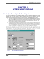
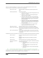
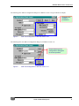
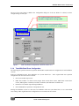
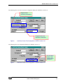
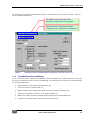
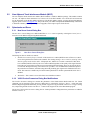
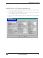
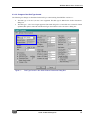
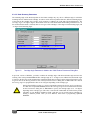
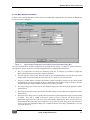
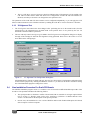
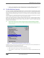
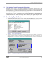
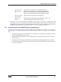
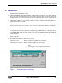
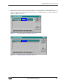
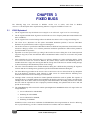
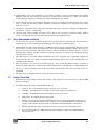
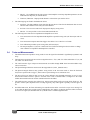
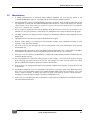
Release Notes WITE32 Version 3.11 6/28/2004 Copyright 2004 Guzik Technical Enterprises. All rights reserved WITE32 Release Notes Version 3.11 Table of Contents Chapter 1 New Hardware Supported in WITE32 .................................................................................................... 3 1.1 Support of Servo Revision 3 for RWA-2000 Series ....................................................................................................................................3 1.2 Comb Loader for Guzik V2002 Spinstands ................................................................................................................................................3 1.3 Ping Pong Cartridge Design for Guzik 1701A+ Spinstands .......................................................................................................................3 1.4 Micro Actuator Support for Guzik V2002 Spinstands .................................................................................................................................4 1.4.1 Hardware Compatibility.................................................................................................................................................................4 1.4.2 Micro Actuator Tests .....................................................................................................................................................................4 1.5 Head Amplifiers ..........................................................................................................................................................................................5 1.6 Head Stacks ...............................................................................................................................................................................................5 1.7 Support of Head Amplifier Multiplexer ........................................................................................................................................................5 Chapter 2 WITE32 Modifications ............................................................................................................................. 6 2.1 2.2 2.3 New System Erase and System Band Erase Configuration .......................................................................................................................6 2.1.1 Using System Erase In WITE32 Tests..........................................................................................................................................8 2.1.2 Tests Without Erase Configuration ...............................................................................................................................................8 2.1.3 Tests With Erase Configuration ....................................................................................................................................................8 2.1.4 Tests With Band Erase Configuration.........................................................................................................................................10 2.1.5 Tests With Erase Preconditioning...............................................................................................................................................12 New Adjacent Track Interference Module (WATI) ....................................................................................................................................13 Spinstands and Servo...............................................................................................................................................................................13 2.3.1 New Servo Control Dialog Box ...................................................................................................................................................13 2.3.2 V2002 Product Parameters Dialog Box Modifications ................................................................................................................13 2.3.3 XY Alignment Test ......................................................................................................................................................................18 2.4 New Installation Procedure For Guzik PCI Boards...................................................................................................................................18 2.5 The Write With Retries Operation.............................................................................................................................................................19 2.6 TAA Calibration Through Programmable Differentiator ............................................................................................................................20 2.7 Error / Warning Report Modification .........................................................................................................................................................20 2.8 Head Selection in the WITE32 Engineering Dashboard...........................................................................................................................21 2.9 Miscellaneous ...........................................................................................................................................................................................22 Chapter 3 Fixed Bugs ............................................................................................................................................. 24 3.1 V2002 Spinstand ......................................................................................................................................................................................24 3.2 Other Spinstands and Servo.....................................................................................................................................................................25 3.3 Analog Front End......................................................................................................................................................................................25 3.4 Tests and Measurements .........................................................................................................................................................................26 3.5 Miscellaneous ...........................................................................................................................................................................................27 Chapter 4 Support of Microsoft Windows XP Operating System ...................................................................... 28 Chapter 5 Known Issues ........................................................................................................................................ 29 Guzik Technical Enterprises 2 WITE32 Release Notes Version 3.11 CHAPTER 1 NEW HARDWARE SUPPORTED IN WITE32 1.1 Support of Servo Revision 3 for RWA-2000 Series WITE32 software version 3.11 supports the RWA-2000 series of testers equipped with Servo Revision 3. Please refer to the Guzik Servo Revision 3 For RWA-2000 Series document P/N 02-107283-03 for more details on the new features of Servo Revision 3. From the operation and WITE32 user interface point of view, Servo Revision 3 is the same as Servo Revision 2. Please refer to the WITE32 Servo User's Guide document P/N 02-106596-01 for more details on how to use Guzik Servo. Servo Revision 3 is not supported by previous versions of WITE32 software. You may get various error messages related to servo misconfiguration if you run previous versions of WITE32 on the RWA equipped with Servo Revision 3, for example, "Spinstand Error. Incorrect parameter value. Only 3 burst gates servo mode is supported: 5 ". Note: In WITE32 version 3.11, an RWA-2000 series equipped with Servo Revision 3 is compatible with Guzik V2002 and Canon spinstands only. The servo will not be available if you connect Servo-3 RWA to Servo-2 or Servo-1 Guzik 1701 or 312 spinstand. 1.2 Comb Loader for Guzik V2002 Spinstands Starting from WITE32 version 3.11 the new head loading mechanism is supported for V2002 spinstand (Comb Loader). Please refer to the Comb Loader Installation document P/N 02-107281-01 or 02-107281-02 for more details on the Comb Loader installation and configuring your V2002 spinstand for operation with the new loading mechanism. 1.3 Ping Pong Cartridge Design for Guzik 1701A+ Spinstands The WITE32 software version 3.11 supports a Ping Pong cartridge designed for HLM-2F Head Loading Mechanism of Guzik 1701A+ Guzik Spinstands. The Ping Pong cartridge was initially designed for the Head Loading Mechanism HLM-3F on 1701B Guzik Spinstands. The Ping Pong cartridges have a special design, which allows to use the head mounted on the top cartridge with the bottom amplifier, or the head mounted on the bottom cartridge with the top amplifier. Guzik Technical Enterprises 3 WITE32 Release Notes Version 3.11 1.4 Micro Actuator Support for Guzik V2002 Spinstands A Micro Actuator is a device located on the suspension of a magnetic head that can transform applied voltage to the radial displacement of the head. Micro Actuator testing is supported on Guzik V2002 Spinstands starting from WITE32 version 3.11. The Micro Actuator configuration and operation is described in the Micro Actuator Tests User's Guide P/N 02107264-02. Please also refer to section 2.3.2.4 on page 17 of this document for additional details on Micro Actuator configuration. 1.4.1 Hardware Compatibility Your test system hardware must be compatible with Micro Actuator in order to run Micro Actuator tests. A new Micro Actuator item is added to the Info | Hardware Features dialog box. If the Micro Actuator item is marked with the green check box, it means that all the required hardware and cables are installed and compatible with Micro Actuator. The list in the round brackets shows whether CW, CCW, or both Head Amplifiers are compatible with Micro Actuator. Figure 1 Hardware Features Dialog Box For upgrade pricing, please contact [email protected] and provide them your RWA and Spinstand EEPROM Dump information if your test system requires an upgrade. 1.4.2 Micro Actuator Tests There are two Micro Actuator tests available in WITE32 version 3.11: • Micro Actuator Stroke test • Micro Actuator Frequency Response test Please refer to the Micro Actuator Tests User's Guide P/N 02-107264-02 for the description of the tests. These tests are included into the Spinstand 2002 Tests module. The module is provided on the WITE32 Installation CD, however the Micro Actuator tests require a license. Please contact [email protected] to obtain a quotation for Micro Actuator tests license. Guzik Technical Enterprises 4 WITE32 Release Notes Version 3.11 1.5 Head Amplifiers The following head amplifiers are initially supported in WITE32 version 3.11: 1.6 • 81G214M • 81G5114D • 81G5114P • GTEMR4PP • MINI • MR5M_M • MUX_SR1795BAA • PA7500 • PA7501 • PA7515 • SR1671 • SR1850B • SR1852 • SR1880 • TLS26A954AA • TLS26D714 • WABASH3x2 Head Stacks The following head stacks are initially supported in WITE32 version 3.11: 1.7 • 81G214M – MAGELLAN_81G214M • PA7540B – NOVA_PA7540B • SR1641 – SCORPIO_1641 • SR1784 – NOVA_SR1784 • WABASH3 – WABASH3 Support of Head Amplifier Multiplexer WITE32 software version 3.11 supports the Head Amplifier Multiplexer P/N S23-318690-01. Guzik Technical Enterprises 5 WITE32 Release Notes Version 3.11 CHAPTER 2 WITE32 MODIFICATIONS 2.1 New System Erase and System Band Erase Configuration Two new system configuration sets are introduced in WITE32: System Erase and System Band Erase. All tests and operations, which invoke erase operation or band erase operation, use the System Erase and System Band Erase settings or allow you to specify custom parameters for erase or band erase. This modification has two purposes: 1. The AC erase operation must be invoked in all tests and operations for perpendicular magnetic recording. In earlier versions of WITE32, except for some special requirement of a test, an erase operation or a band erase operation means that a positive direction DC erase operation is done with the existing write current. The new system options make the erase operation configurable. 2. You can configure erase parameters in one dialog box and use this one common set of parameters in all tests and operations, rather than configuring many tests separately. This simplifies WITE32 product maintenance when you need to change one of the erase parameters, for example, the erase current. Starting from WITE32 version 3.11 it can be done in a common place – System Erase and System Band Erase dialog box. The System Erase configuration is for erase operation performed on a single track, while System Band Erase is for erase operation performed on a band of tracks. A new Control | Band Erase menu item is added to WITE32, which includes both System Erase and System Band Erase configurations. When you click the Band Erase item on the Control pull-down menu of WITE32 Engineering Dashboard, the following dialog box is displayed: Figure 2 New System Band Erase Dialog Box Guzik Technical Enterprises 6 WITE32 Release Notes Version 3.11 There are two frames in the dialog box – the Erase Parameters frame and the Band Erase Parameters frame. The Erase Parameters frame allows you to define the erase configuration. The Iterations text box Defines the number of repetitions for each erase operation at each offset The Mode option buttons Defines the erase modes: • Positive DC – the DC erase operation using the positive write current for one revolution. • Negative DC – the DC erase operation using the negative write current for one revolution. • Positive DC / Negative DC – the DC erase operation using the positive write current for the first revolution, followed by the DC erase operation using the negative write current for the second revolution. • Negative DC / Positive DC – the DC erase operation using the negative write current for the first revolution, followed by the DC erase operation using the positive write current for the second revolution. • AC – the AC erase operation for one revolution with the frequency defined in the Frequency text box. The Frequency text box Defines the frequency for the AC erase operation, in MFlux/s. The Write Current text boxes Define the write current values (in mA) used in the erase operation. You can configure individual write current for the first and the second revolution. The Use System check boxes If the check box is checked, the Write Current text box value for the corresponding revolution is ignored. The current system write current is used instead. The Band Erase Parameters frame allows you to define the area around the current track for the band erase operation. Note: The From text box Defines the starting offset position for the band erase operation, in µInch. The To text box Defines the ending offset position for the band erase operation, in µInch. The Step text box Defines the offset step size for each erase operation, in µInch. The Interleave Band Erase check box If it is checked, the Mode option is ignored. The band erase operation is done in the following way: 1. Erase using the positive write current at the first offset position. 2. Erase using the negative write current at the second offset position. 3. Erase using the positive write current at the third offset position, etc. The band erase area is specified in terms of the head writer offset (in µInch) in respect to the center of the track. All System Erase and System Band Erase parameters are zone/setup dependent, you can double-click on the parameter label to specify the value of the parameter for each zone and setup. Guzik Technical Enterprises 7 WITE32 Release Notes Version 3.11 CAUTION: When you upgrade tos WITE32 version 3.11 from the previous versions of WITE32, the product update procedure performs the conversion of the old band erase configuration (specified in terms of number of tracks to erase) to the new band erase configuration (specified in terms of From, To, and Step values). This conversion uses the track size value specified in the Product Parameters dialog box for the selected spinstand driver. Please make sure that you use proper spinstand driver and correct track size before you update your product to WITE32 version 3.11. ! 2.1.1 Using System Erase In WITE32 Tests All Guzik tests have been modified to use the system erase or system band erase configuration. An erase (or band erase) operation by a test is done in one of the following ways: 1. If a test does not have its own erase (or band erase) operation configuration, the system erase (or band erase) configuration settings will be used to erase the media. 2. If a test has its own configuration, it can be configured to either use system erase (or band erase) operation setup, or to override the system erase (or band erase) operation setup with the custom settings. 2.1.2 Tests Without Erase Configuration The following tests perform erase operation and were hard coded to erase the media using a Positive DC mode in earlier WITE32 versions: • MR Tests module: Write-Impedance and Head Polarity tests. • Parametric Tests module: Parametric, PWN Stability, Overwrite, and Amplitude Stability tests. • PRML Tests module: Guzik Channel Optimization test. • Composite Tests module: Frequency, Triple-Track, and Saturation tests. • WITE Control module: Servo Calibration operation. Starting from WITE32 version 3.11 these tests use System Erase configuration. 2.1.3 Tests With Erase Configuration The following tests perform an erase operation and had their custom erase configurations in earlier WITE32 versions: • 747 Tests module: 747 Comparator test. • Digital Parametric Tests module: Digital Parametric test. • Parametric Tests module: SNR and Spectral SNR tests. Starting from WITE32 version 3.11 these tests are modified to either use System Erase configuration, or use custom erase settings. Their original erase operation configurations are converted to the new format of the custom erase settings. Guzik Technical Enterprises 8 WITE32 Release Notes Version 3.11 The following is the SNR test configuration dialog box in WITE32 version 3.10 (provided as an example): Original erase operation parameters Figure 3 SNR Test Configuration in WITE32 version 3.10 The following is the new SNR test configuration dialog box in WITE32 version 3.11: A new button opens a configuration dialog box for erase operation Figure 4 SNR Test Configuration in WITE32 version 3.11 Guzik Technical Enterprises 9 WITE32 Release Notes Version 3.11 The new Erase Setup button is added to the configuration dialog box of the test. When it is clicked, an Erase configure dialog box will open: The caption shows which test erase operation configuration is being edited Selects between using a System Erase configuration or Custom Erase configuration Figure 5 2.1.4 SNR Test Erase Configuration in WITE32 version 3.11 Tests With Band Erase Configuration The following tests perform a band erase operation and had their custom band erase configurations in earlier WITE32 versions: Some test configurations have been modified to use System Band Erase. Their original band erase operation configurations are converted to the new format: • Error Tests module: Popcorn test. • GMA Tests module: Low Erase Current, Single Track Critical Erase Current, Multi-Track Critical Erase Current, Missing Pulse Avalanche, Extra Pulse Avalanche, and Undershoot Avalanche tests. • Parametric Tests module: Spectral Integral SNR test. • Erase and Band Erase operations of the production test. Starting from WITE32 version 3.11 these tests are modified to either use System Band Erase, or use custom band erase settings. Their original band erase configurations are converted to the new format. Guzik Technical Enterprises 10 WITE32 Release Notes Version 3.11 The following is the Low Erase Current test configuration dialog box in WITE32 version 3.10: Original erase operation parameters Original band erase operation parameters Figure 6 Low Erase Current Test Configuration in WITE32 version 3.10 The following is the new configuration dialog box in WITE32 version 3.11: A new button opens erase configuration dialog box Figure 7 Low Erase Current Test Configuration in WITE32 version 3.11 Guzik Technical Enterprises 11 WITE32 Release Notes Version 3.11 The following is an example of the Band Erase dialog box, which opens after you press the Erase Setup… button in the test configuration dialog box: The caption shows which test erase operation configuration is being edited Selects between using a System Erase configuration or Custom Erase configuration Figure 8 2.1.5 Low Erase Current Test Band Erase Configuration in WITE32 version 3.11 Tests With Erase Preconditioning A new System Erase option is added to preconditioning selection of WITE32 tests. When this option is selected, the System Erase configuration will be used for preconditioning. The following is the list of the tests, which include this new preconditioning option: • Digital Parametric Tests module: Digital Parametric test. • Error Tests module: Comparator Error test. • MR Tests module: Pulse Stability, Pulse Width Asymmetry, and TAA Asymmetry tests. • Parametric Tests module: Asymmetry, TAA, and Pulse Width tests. • PRML Tests module: Sequenced Amplitude Margin and Sampled Value Distribution tests. • Composite Tests module: Triple Track Profile and Pulse Profile tests. Guzik Technical Enterprises 12 WITE32 Release Notes Version 3.11 2.2 New Adjacent Track Interference Module (WATI) The new Adjacent Track Interference module (WATI module) is added to WITE32 package. This module contains one test – the Adjacent Track Interference test. Please refer to the WATI Module Users Guide (P/N 02-107268-02) for the description of the WATI module and the test. The WATI module requires a license and possible hardware upgrade; please contact [email protected] and provide them your RWA and Spinstand EEPROM Dump information to determine whether your test system requires an upgrade, and to request a quote for the license. 2.3 Spinstands and Servo 2.3.1 New Servo Control Dialog Box The new Servo Control dialog box is added in WITE32 rev 3.11. It can be opened by selecting the Control | Servo… menu item in the WITE32 Engineering Mode Dashboard. Figure 9 New Servo Control Dialog Box This dialog box has two check box controls: 1. Disable Servo Control if Loop is Unstable. If this check box is enabled, WITE32 turns off the servo control in case the signal from the head becomes unstable. The warning message “Servo control is turned off. Check that the signal from the head is stable” is displayed once, and the servo control is turned off. If this check box is disabled, WITE32 will keep the servo control enabled regardless of the quality of the signal from the head. This may result in the recurring error messages during head positioning, however, the system will try to control the head position using servo whenever it is possible. It is recommended to enable this option in the production environment, such that testing the heads producing poor signal can be finished in non-servo mode. This control is available only for Guzik V2002 spinstands. For all other spinstands this check box is disabled. 2. MA Enable – This control is reserved for future use with Micro Actuator. 2.3.2 V2002 Product Parameters Dialog Box Modifications The Product Parameters dialog box contains the parameters of the Head and the Media under test. For V2002 spinstand, you can open the Product Parameters dialog box by selecting the Configure | Device… menu item in the WITE32 Engineering Mode Dashboard, pressing the Run Alignment Program button in the Device Configure dialog box, and pressing the Edit Product Parameters… button on the Equipment tab of the WDCP2002 program. The layout of the Product Parameters dialog box for V2002 spinstand is changed and new parameters are added in WITE32 version 3.11. Guzik Technical Enterprises 13 WITE32 Release Notes Version 3.11 2.3.2.1 Dialog Box Layout and Tab Pages The parameters in the Product Parameters dialog box are grouped into three tab pages: • The Disk tab page. This page contains controls and parameters related to disk geometry such as disk type, minimum radius, maximum radius, direction of rotation and speed (RPM), device options, disk working area, skew angle parameters, start and stop options. • The Heads tab page. The page contains a number of parameters related to head geometry such as head base offsets, cartridge angle, and head length of CCW and CW heads. • The Micro Actuators tab page. This page has information about configuration of Micro Actuators installed in the system. Figure 10 Three Tabs in the V2002 Product Parameters Dialog Box Guzik Technical Enterprises 14 WITE32 Release Notes Version 3.11 2.3.2.2 Changes of the Disk Type Control The following two changes are introduced in the Disk Type control starting from WITE32 version 3.11: • The Disk type 2.756 Inch (70 mm) is now supported. This disk type is added to the Product Parameters dialog box. • The Disk type 1.3 Inch is no longer supported. The chuck design for 1.3 Inch disk never existed for V2002 spinstand, this option is removed from the Disk Type control in the Product Parameters dialog box. Figure 11 Disk Type Control in the V2002 Product Parameters Dialog Box Guzik Technical Enterprises 15 WITE32 Release Notes Version 3.11 2.3.2.3 Head Geometry Parameters The mounting angle of the head suspension on the V2002 cartridge may vary due to a different angle, in which the mounting block is installed on the cartridge. In order to switch between products that have different mounting angles of the head on the cartridge the Cartridge Angle parameter is added to the CCW and CW Head Parameters. The Cartridge Angle is an angle in degrees between the center line of the head and the head loading mechanism axis. At the moment this document is released, there are two types of the cartridges: with 0 degrees head mounting angle, and –10 degrees head mounting angle. Figure 12 Cartridge Angle Parameter is Added to the V2002 Product Parameters Dialog Box In previous versions of WITE32, you had to combine the cartridge angle with the head loader angle and store the resulting value in the spinstand EEPROM. The cartridge angle (0 or –10 degrees) was added to the head loader angle in respect to the XY stage of the spinstand (the V2002 head loader has a 45 degree angle) and specified in the Tooling Angle text box on the Tooling Parameters tab of the Spinstand Parameters dialog box of WDCP2002. The value in the Tooling Angle was programmed to either 45 or 35 degrees depending on the cartridge type. ! Starting from WITE32 version 3.11, Guzik recommends to change the Tooling Angle to 45 degrees, save this value to spinstand EEPROM, and use the Cartridge Angle text box on the Heads tab of the Product Parameters dialog box of WDCP2002 to specify the cartridge angle (0 or –10 degrees depending on the cartridge type). This value is stored in the V2002.DDT file located in the product sub-folder of your WITE32 installation folder, such that you can switch between cartridges by loading a different product when you start WITE32, rather than re-programming spinstand EEPROM. Guzik Technical Enterprises 16 WITE32 Release Notes Version 3.11 2.3.2.4 Micro Actuator Parameters In order to start working with Micro Actuator it has to be enabled and configured. The new controls are added to the Product Parameters dialog box. Figure 13 Micro Actuator Parameters in the V2002 Product Parameters Dialog Box The controls for the Micro Actuator configuration are grouped into two frames – CCW Micro Actuator Parameters and CW Micro Actuator Parameters. The following parameters are configured for each actuator: • The Use Configuration File check box. Enable this check box to configure your product to support the Micro Actuator and to specify the Micro Actuator parameters. • The read-only File Name text box shows the name of the corresponding Micro Actuator file in the current product folder. You can not modify the name of the file, it is shown for your reference only. • The Device control enables or disables the hardware control of the Micro Actuator for the current product configuration. If you choose to disable the device, the hardware will not apply voltage to the Micro Actuator when the spinstand is started, and Micro Actuator tests will not be available. • The Voltage Range Min text box specifies the minimum voltage (in Volts) allowed to be applied to a Micro Actuator device. • The Voltage Range Max text box specifies the maximum voltage (in Volts) allowed to be applied to a Micro Actuator device. • The Displacement Range text box specifies the expected peak-to-peak displacement range of micro actuator (in µInch). This value is needed in the Micro Actuator Frequency Response test. Please specify an approximate range in this entry. This entry can be automatically updated by the Micro Actuator Stroke test, which measures the actual range. Please enable the Program Micro Actuator Range check box in the Micro Actuator Stroke test configuration dialog box to update the Displacement Range automatically every time you run the Stroke test. Guzik Technical Enterprises 17 WITE32 Release Notes Version 3.11 • The Use CCW Micro Actuator Parameters check box indicates that CCW parameters will be applied to the CW Micro Actuator. Please enable this check box if configurations of both CW and CCW actuators are identical, such that you do not have to configure the same parameter twice. The parameters of the CCW and CW micro actuators can be configured independently, or you can apply the CCW Micro Actuator Parameters to the CW Micro Actuator by enabling the CCW Micro Actuator Parameters check box. 2.3.3 XY Alignment Test 1. The XY Alignment test behavior has been changed. After performing the test in the manual mode (from the stopped device), the spinstand leaves the head loader in the position where it was placed by the user. No movement to the home radius is performed. 2. The new read-only control Cartridge Angle is added to the XY Alignment test configuration dialog box to display the angle of the cartridge for which the XY alignment is being performed. Please refer to the section 2.3.2.3 for more details on the cartridge angle. Figure 14 XY Alignment Test Configuration Dialog Box All Head Parameters controls are made read-only, since they are shown on the XY Alignment configuration form for the reference purpose only. Starting from WITE32 version 3.11 you must use the Product Parameters dialog box of the WDCP2002 program to change these values. 2.4 New Installation Procedure For Guzik PCI Boards The WITE32 installation program version 3.11 contains a new revision and a modified installation procedure of the PCI driver. The procedure introduces the following features: • The special procedure to eliminate a conflict with on-board USB 2.0 controller is no longer required. Please refer to section 7.1 "Windows 2000 Crashes After Installation of WITE32" of WITE32 Release Notes Version 3.10 document for the description of the special procedure. • In most cases, the installation of a new version of WITE32 and/or Guzik Technical Enterprises PCI boards does not require to reboot a computer. Guzik Technical Enterprises 18 WITE32 Release Notes Version 3.11 • 2.5 Changes in the configuration of Guzik Technical Enterprises PCI boards (adding/removing/changing PCI slot) on the host computer do not require to reinstall the driver from the WITE32 installation disk. The Write With Retries Operation A new type of operation is implemented in WITE32 revision 3.11: the Write With Retries operation. This is a special case of the write operation when the RWA shuts down the write gate in the sectors, in which the spinstand detects that the Position Error Signal (PES) exceeds the specified tolerance. The software can repeat attempts to write the failed sectors until the specified percentage of the sectors is successfully written or the maximum number of attempts is reached. The spinstand generates a signal indicating that the Position Error Signal is within the specified tolerance. The PES in Tolerance signal is provided to the Scope Point 7 output of the spinstand control box. In order to use the Write With Retries operation you must connect the Scope Point 7 output to the Index In input of RWA using a BNC-to-BNC cable, and check the Enable “Write With Retries” Operation check box in the Measurement Options dialog box (click the Configure | Measurement Options…menu item of WITE32 Engineering Dashboard to open the dialog box). Note: Never connect the Scope Point 7 of the spinstand control box to the Index In connector of RWA before you enable the Write With Retries Operation check box. If you do not enable the check box, the spinstand Control Box will provide the Position In Tolerance signal to the Index In connector of RWA, and WITE32 will not perform RWA initialization properly due to incorrect index signal. Figure 15 Measurement Options Dialog Box in WITE32 version 3.11 In WITE32 version 3.11 only ATI test uses the Write With Retries operation, please refer to the WATI Module Users Guide (P/N 02-107268-02) for more details on the ATI test. The following hardware is required for the Write With Retries operation: • RWA Control board revision R or later installed in the Read Write Analyzer. • Servo Controller 3+ revision G or later, or any revision of Servo Controller 4 board installed in the SCB2002 box. Guzik Technical Enterprises 19 WITE32 Release Notes Version 3.11 2.6 TAA Calibration Through Programmable Differentiator Starting from WITE32 version 3.11, the calibration of amplification of programmable differentiator filters is not performed during TAA calibration. All programmable differentiators are assumed to have the same amplification at their cutoff frequencies as the Open filter. This means that if the spectral content of the signal is located below the cutoff frequency of a programmable differentiator, then the amplitude measured through this differentiator will decrease (approximately linearly) with the increase of the cutoff frequency. In previous releases of WITE32, the amplification of the programmable differentiator was calibrated during TAA calibration regardless of the current cutoff frequency and the calibration signal spectral content. This led to unpredictable measurement results in the case of changes of the cutoff frequency or the signal frequency. 2.7 Error / Warning Report Modification 1. The information about WITE32 software version is added to the standard WITE32 error message box, when shown in the More Info mode. The WITE32 software version is printed on the first line of the error report. Figure 16 2. Error / Warning Dialog Box The existing Errors at The Test End option is extended. In previous versions of WITE32, if this option is enabled, the buffered messages are only shown in a separate dialog box at the end of the production test. In WITE32 version 3.11 you can specify a log file name, such that the buffered error messages are also appended to the log file. Figure 17 Test Options Dialog Box with Error Log File Name Control Guzik Technical Enterprises 20 WITE32 Release Notes Version 3.11 3. 2.8 The Errors at The Test End check box If the check box is checked, no error messages during the production test will be shown. The buffered messages will be shown in a separate dialog box at the end of the production test. Moreover, the buffered messages will be appended to a log file. The Error Log File Name text box The text box shows the log file name with a path. The file open button “…” When the button is clicked, a File Open dialog box is shown. You can specify the path and file name for the log file. If the Errors at The Test End check box is enabled in the Configure | Test Options… dialog box, the full information on every error is included to the detailed error output, which is shown in the More Info mode of the standard WITE32 error message box (see Figure 16 above). In previous versions of WITE32, only the basic error information is shown in the More Info mode when the Errors at The Test End option is enabled. Head Selection in the WITE32 Engineering Dashboard The behavior of the Head selection frame of the WITE engineering dashboard is changed. If you change the maximum number of heads in the Head No field of the Maximum Limit frame of the Configure | Device dialog box, then: 1. All heads selected in the Head Selection table of the Configure | System dialog box, with numbers more than the maximum head number, are deselected. 2. If all heads become deselected as a result of changing the value of the maximum number of heads, then the Head 0 is selected. 3. If the number of the current head in Head frame of the WITE32 Engineering Dashboard is more than the new value of the maximum number of heads, a head from the list of selected heads with a maximum number is set as the current head. Guzik Technical Enterprises 21 WITE32 Release Notes Version 3.11 2.9 Miscellaneous 1. The maximum number of result records in the WITE32 result processor is doubled so that more test results (up to 200,000) can be accommodated at run-time. 2. The new signal WOPEN (Write Operation Enable) is added to the list of available sources for RWA output scope points. This signal can be selected in the Control | Scope Point… dialog box. It can be assigned to Scope Point 3 and Scope Point 4 BNC connectors of RWA-2000 series, or Scope Point 3 BNC connector of RWA-2550 and RWA-2585 series. This signal is available if your RWA has an RWA Control Board Revision “R” or later. 3. The limitation of the number of test iterations in the Sector Amplitude Stability test configuration dialog box is increased from 32767 to 2147483647. 4. The obsolete Micro Actuator operations Turn Micro Actuator On (MAct ON) and Turn Micro Actuator Off (MAct OFF) are removed. Please refer to the Micro Actuator Tests User's Guide P/N 02-107264-02 for the details on the Micro Actuator operations. 5. If an external module registration fails, an error message is displayed to explain the reason. 6. A backup file is always created when a database file in the product folder is updated. The updated database file is compacted to reduce the file size afterward. In previous versions of WITE32, the size of the database files (for example, RWA.MDB) might have been increasing several times after the database update when upgrading the version of WITE32. 7. The PRML chip adapter driver list on product selection menu is sorted in ascending order based on the chip adapter driver name. 8. New parameters are added to the Write Pattern operation: The # of Rev text box Defines the number of revolutions to write the pattern. The Keep Pattern combo box Defines the action to be done after pattern writing: Figure 18 • Keep Test Pattern – leave the write pattern as the current pattern. • Restore Original – restore the pattern to the one before writing. Write Pattern Operation Configuration Guzik Technical Enterprises 22 WITE32 Release Notes Version 3.11 9. More descriptive names are used to show the parameters in an operation test configuration dialog box. In WITE32 version 3.10 and earlier, generic internal names are used in the dialog box. For example, “WrtFlux” is used for the flux reversal value in the WriteFlux operation test of WITE32 version 3.10, which is renamed to “Mflux/s” in WITE32 version 3.11: Figure 19 Parameter Caption In WITE32 version 3.10 Figure 20 Parameter Caption In WITE32 version 3.11 Guzik Technical Enterprises 23 WITE32 Release Notes Version 3.11 CHAPTER 3 FIXED BUGS The following bugs were discovered in WITE32 version 3.10 or earlier, and fixed in WITE32 version 3.11. The description below explains the bug behavior as it appears in WITE32 version 3.10. 3.1 V2002 Spinstand 1. The XY Alignment test may fail with the "Servo amplifier is not calibrated - signal is too low" error message. 2. The XY Alignment and the Head Alignment tests fail in the case of low frequency heads (the heads with data rates below 160 Mbit/s). 3. The XY Alignment test resets the loading radius to the default value in the Product Configuration dialog box. 4. The Y-limit Screw Adjustment test fails (shows unreachable destination position) if non-zero Head Base Parameters are specified in the Product Configuration dialog box. 5. The Product Parameters specified in V2002.DDT in Inches are different from parameters shown in Edit Product Parameters dialog by 0.002%. As a result the parameters loaded into spinstand are different from parameters specified in DDT file by 0.002%. 6. Impossible to use the Special Disk Type setting in the Product Parameters dialog box of the V2002 Spinstand Alignment Program, because the Minimum Radius and Maximum Radius values are not stored in the product database. 7. After performing the Y-limit Adjustment there is no software validation of Y-stage positioning and the Y-limit screw can be hit. In the new version of WITE32, the software always checks if the destination position is reachable before the Y-stage starts moving such that the Y-stage does not hit the screw and the warning message is shown when the specified destination position is out of range. 8. The value of the Reset Radius in the Product Parameters dialog box is different after performing XY Alignment with zero and non-zero head geometry parameters specified in the Product Parameters dialog box. 9. The V2002 Balancing procedure for the Custom 6 Screws and Custom 3 Screws choices from the Type dropdown list of the Balancing Parameters frame instructs to adjust screws for counter-clockwise balancing screw numeration instead of clockwise balancing screw numeration. 10. Cartridge, which is incorrectly installed on V2002 spinstand could hit the media or spindle. The sequence of starting the device is modified such that the spinstand checks that the required level of vacuum is provided to the cartridge before the X and Y motors start moving the V2002 head loader to the loading location. If the vacuum does not reach the required level due to improperly installed cartridge, the spinstand will not move and will provide an error message. 11. The V2002 Balancing while executed for rotation speeds higher then 10000 RPM consists of 4 stages in the case of high imbalance: • Screw Calibration for reduced RPM, • Balancing for reduced RPM, • Screw Calibration for full RPM, • Balancing for full RPM. In WITE32 version 3.10 the Screw Calibration for full RPM shows the wrong instruction to "Switch to Balancing Tab to perform Balancing procedure" instead of instruction to continue with screw calibration. Guzik Technical Enterprises 24 WITE32 Release Notes Version 3.11 12. In WDCP2002, when some spinstand tests are running, an attempt to load or unload Add-Ins from Add-Ins Manager dialog may cause several error messages. To avoid this the menu item File | Addin... that opens the Add-Ins Manager dialog box is disabled if one of the WDCP2002 tests is running. 13. The Head Alignment test fails with unclear diagnostics if the service track for the Head Alignment test is written using a voltage read bias mode amplifier, and then you change the amplifier or the bias mode to the current mode, or vice versa. 14. The range of valid values for the Y Base Offset parameter in the Product Parameters dialog box of WDCP2002 is increased to –10 Inch ... +10 Inch range. 15. The time stamp of the spinstand errors shown in the WITE32 error messages is calculated wrongly. WITE32 version 3.10 shows the time since the spinstand reset instead of the astronomical time. 3.2 3.3 Other Spinstands and Servo 1. For all Guzik 1701 and 312 spinstands, the Balancing procedure option N (balancing cap: 2.5) and option O (balancing cap: 1.8) shows instructions for 6 balancing screws instead of 3 balancing screws. 2. The Head Stack acoustic sensor emergency is handled wrongly on Guzik 1701B spinstands. When the acoustic sensor detects a scratch on the disk during Start Device, the spinstand immediately displays the Emergency Recovery Procedure dialog box and requires operator to unload a Head Stack manually. The new version of WITE32 stops operation, unloads a Head Stack normally, and then provides the proper diagnostic message "Acoustic Sensor detected". 3. The PES Acquisition from Data method of the PES Analysis test is available only for spinstands equipped with Guzik Servo Revision 2 (i.e. Guzik S1701B and V2002 spinstands). In the new version of WITE32 this test is available for all spinstands. 4. The error message “No response from spinstand after IPL” occurs in the IPL Mode when Servo Controller or Motion Controller DSP code is corrupted in the spinstand flash memory. This bug affects 1701B spinstands only. 5. The Servo Calibration dialog box shows the Track Width value instead of the Track Pitch value for Servo-1 spinstands. 6. The erase step size validation in the Servo Erase operation test always fails. Analog Front End 1. WITE32 does not report MR5 overheat error message “Head Amplifier Overheating Detected” when the MR5 board is overheated. 2. The following bugs are fixed in the head amplifier drivers: • 81G5114 – Bit 3 in the undershoot register (USC[3]) is set to 1 on start. • GTEMR5 – The amplifier P/N 23-321300-01 does not turn off power on Stop Device. • GTEMR5 – the WDK function OvershootStepGet() always returns zero. • MR51796M – No readback from the chip registers. • MR5M – Any test (except for the Production test) started by pressing the Soft Button in the Operator Panel does not reload head amplifier zone parameters. As a result the MR5M head amplifier does not properly set the read bias and write current on start and fails the MR-Impedance measurement. • MR5M – Intermittently fails to set read bias on start device (sets bias to unpredictable value). • PA7515, SR1774, SR1796 – WDK functions OvershootStepGet () and OvershootWidthStepGet() always return zero. Guzik Technical Enterprises 25 WITE32 Release Notes Version 3.11 3. 4. 3.4 • SR1715 – No readback from the chip registers. Head Amplifier zone/setup dependent parameters are not loaded into the chip after you start the device. • TDA5160, TDA5360 – Improper head channel is selected after you start the device. The following bugs are fixed in the head stack drivers: • 81G5108 – The fault condition is not cleared on the start device. Therefore the head stack does not work after the fault condition occurs until you restart WITE32. • PA7540 – The Overshoot and Vendor ID properties display wrong values. • SR1796 – It is not possible to select a head other than head zero. The following issues related to low impedance head amplifiers are fixed: • TAA measurement for low impedance head amplifiers reported in wrong units (mV instead µA and vise versa). • TAA measurement reports 1000 times bigger value in the Convert Results to mV mode. • TAA calibration procedure reports wrong units (mV instead µA) . • The Output Impedance of Injector control in the TAA Calibration dialog box does not allow to change value when the low impedance head amplifier is installed. Tests and Measurements 1. The PW50 measurement produces wrong results in case the signal from the head is significantly asymmetric and noisy. 2. The band erase operation in the Overwrite test algorithm erases –T/4, 0, and +T/4 offsets rather than –T/2, 0, and T/2 (where T is the track size). 3. The COV Detection Type in Popcorn measurements (accessible through WDK based external modules only) causes an assertion. 4. The Spectral Integral SNR test cannot run on the stopped device (in the _ZOutside zone). 5. The Spectral Integral SNR test may produce wrong results in the non-sector mode or when the Enhanced Performance option in the Configure | Measurement Options dialog box is switched to None. 6. The Spectral Integral SNR test does not use the values defined in the spinstand parameters in case Use Spin Stand Load/Unload Parameters option is selected. If the Load or Unload radius is configured to the radius smaller than OD radius the test loads or unloads head at the OD radius. 7. The artificial spikes, caused by the software bug, appear on the OTRC profile plot in the Triple Track test. The presence of these spikes depends on the test setup. Typically, they either appear repeatedly or do not appear at all. 8. For RWA-2000 series, the TAA calibration gives unstable results and/or "Overload on input" error message if it is run when the Main Gain provides positive amplification. For instance, it happens when the SNR is measured on a noise-free signal (sets the Main Gain to 0), and the TAA is calibrated right after that. Guzik Technical Enterprises 26 WITE32 Release Notes Version 3.11 3.5 Miscellaneous 1. If V2002 spinstand driver is unchecked during WITE32 installation, the error message “Failed to run ‘C:\WITE32\DIME.EXE /regserver’ command” pops up at the end of the installation process. 2. The Head Amplifiers Connect and Head Amplifiers Disconnect operations do not do anything and do not provide any diagnostics if called from the WITE32 dashboard when the device is started. The proper error message "Head Amplifier can be disconnected only if a device is stopped. This operation should be used in a production sequence in ‘_ZOutside’ zone." is added. 3. No test results are reported and stored in the database during the Alternative Overwrite test execution in case when the Low Frequency parameter is selected as Fixed, although the correct values are displayed on the graph. 4. The PWN Asymmetry test displays overflow message box intermittently when the signal amplitude from the head is small. 5. The Position Error Test result values PosErrL and PosErrR are swapped. 6. WITE32 crashes during TAA calibration in the production sequence if the calibration procedure is being repeated in a loop more than 100 times. 7. The Track Profile test does not report any results (even the special –9999 values indicating the error) when the measurements fail. 8. Allocated sectored result memory in the read channel board for RWA-2000 series is smaller than on the RWA2585 and RWA-2550 families of testers. The allocated sectored result memory size is increased. 9. If the type or size of a field in a product database is changed, the product update procedure of WITE32 does not update the database correctly. 10. For some WITE32 tests, combo box control selection is done wrongly. If two items in the list have the same prefix sub-string, only the first item can be selected. For example, in a pattern selection combo box, if HFX pattern is added before HF pattern, HF pattern cannot be selected at all. 11. In the Frequency test configuration dialog box, the boundary validation of the frequency is wrong (the From and To parameters). 12. An attempt to change the From or To parameters in the Relative Track Range frame of the Multitrack Critical Erase Current test in the Media Analysis Tests module (WGMA module) fails. The error message "Not a valid number" appears repeatedly, no matter what values are typed in and what the operator is doing after that – attempting to restore the original settings or closing the configuration form. 13. In the Control | System dialog box the bit cell and flux reversal fields may be displayed in red and green if the bit cell field contain decimal places. Guzik Technical Enterprises 27 WITE32 Release Notes Version 3.11 CHAPTER 4 SUPPORT OF MICROSOFT WINDOWS XP OPERATING SYSTEM Microsoft Windows XP Service Pack 1a (SP1a) is supported in the WITE32 software. You must have the patch 822603 for Windows XP installed before you run WITE32. The table below lists the operating systems approved to work with WITE32 version 3.11: Supported in WITE32 version 3.11 Operating system Windows XP Service Pack 1a with Patch 822603 YES Windows 2000 Service Pack 4 YES Windows 2000 Service Pack 3 YES Windows 2000 Service Pack 2 YES Windows 2000 Service Pack 1 YES Windows 2000 w/o Service Packs YES Windows ME NO Windows CE NO Windows 98 NO Windows 95 NO Guzik Technical Enterprises 28 WITE32 Release Notes Version 3.11 CHAPTER 5 KNOWN ISSUES For Guzik V2002 spinstand, after upgrading from WITE32 version 3.10 to WITE32 version 3.11 it is necessary to rewrite service track for the Head Alignment test, otherwise execution of the test will fail with error message "Service track was not written". Guzik Technical Enterprises 29