1
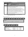
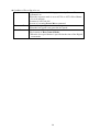
VC-C50i
COMMUNICATION CAMERA
PROGRAMMER'S MANUAL
Ver1.1
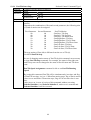
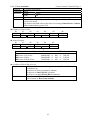
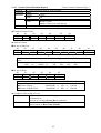
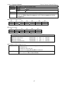
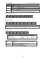
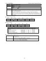
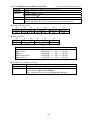
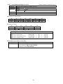
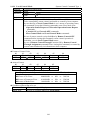
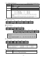
History of revisions
Version
Issue date
Ver1.0
Dec. 25, 2003
Ver1.1
Jan. 05, 2005
Description of revision
First version issued.
1. Maximum values for zoom position 2
assignment, zoom position 2 request and
zoom position maximum request changed to
"07A6."
2. Exposure mode AUTO Slow Shutter added.
3. Dome mode setting and verification
parameter changed to "00, 01" only.
1
Applicable to Ver.6-08
Contents
1. Getting Started...................................................................................................................................... 7
2. Connection with your Computer .......................................................................................................... 7
2.1 Connection .................................................................................................................................. 7
2.2 Connector & Pin Assignment...................................................................................................... 8
3. Communication Format........................................................................................................................ 8
3. Communication Format........................................................................................................................ 9
3.1 Signal Format .............................................................................................................................. 9
3.2 Understanding ............................................................................................................................. 9
3.3 Communication Timing Diagram ............................................................................................. 10
4. Control Command Format ................................................................................................................. 12
5. Answer Format................................................................................................................................... 12
5.1 Answer Format.......................................................................................................................... 12
5.2 Error Code ................................................................................................................................. 12
5.3 Status ......................................................................................................................................... 13
6. Function of Command Termination Notification............................................................................... 14
6.1 Function In General................................................................................................................... 14
6.2 Format of Command Termination Notification ........................................................................ 14
7. Cascade Global Notification .............................................................................................................. 14
7.1 In General.................................................................................................................................. 14
7.2 Format of Cascade Global Notification Data............................................................................ 15
7.3 Notification Code ...................................................................................................................... 15
8. Event Generation Notification Function ............................................................................................ 16
8.1 Overview of Event Generation Notification Function .............................................................. 16
8.2 Event Generation Notification Data Format ............................................................................. 16
8.3 Event Generation Factor Codes................................................................................................. 16
9. Function of Remote Control............................................................................................................... 17
9.1 In General.................................................................................................................................. 17
9.2 Data Format of Remote Control Through ................................................................................. 17
9.3 Table of Remote Control Code ................................................................................................. 18
10. Classification of Command.............................................................................................................. 19
10.1 Classification by Operation..................................................................................................... 19
10.2 Classification by Executive Format ........................................................................................ 19
11. Control Command Table.................................................................................................................. 21
11.1 Pedestal Control Command Table........................................................................................... 21
11.2 Camera Control Command Table ........................................................................................... 22
11.3 System Control Command Table ............................................................................................ 24
12. Details of Pedestal Control Commands ........................................................................................... 26
12.1 Pan Speed Assignment
Pedestal Control Command Type 1........................................... 26
12.2 Tilt Speed Assignment
Pedestal Control Command Type 1........................................... 27
12.3 Pan Speed Request
Pedestal Control Command Type 1................................................. 28
12.4 Tilt Speed Request
Pedestal Control Command Type 1 ................................................. 29
12.5 Pan Tilt Stop
Pedestal control Command Type 1 ......................................................... 30
12.6 Pan Right Start
Pedestal Control Command Type 2 ..................................................... 31
12.7 Pan Left Start
Pedestal Control Command Type 2 ....................................................... 32
2
Pedestal Control Command Type 2 ......................................................... 33
12.8 Tilt Up Start
12.9 Tilt Down Start
Pedestal Control Command Type 2 .................................................... 34
12.10 Home Position
Pedestal Control Command Type 2.................................................... 35
12.11 Pedestal Initialize 1
Pedestal Control Command Type 2.............................................. 36
12.12 Pedestal Initialize 2
Pedestal Control Command Type 2.............................................. 37
12.13 Pan Slowest Speed Request
Pedestal Control Command Type 1 ................................... 38
12.14 Pan Fastest Speed Request
Pedestal Control Command Type 1..................................... 39
12.15 Tilt Slowest Speed Request
Pedestal Control Command Type 1 ................................... 40
12.16 Tilt Fastest Speed Request
Pedestal Control Command Type 1..................................... 41
12.17 Pan Angle Pulse Ratio Request
Pedestal Control Command Type 1 ............................. 42
12.18 Tilt Angle Pulse Ratio Request
Pedestal Control Command Type 1.............................. 43
12.19 Pan Minimum Angle Request
Pedestal Control Command Type 1................................ 44
12.20 Pan Maximum Angle Request
Pedestal Control Command Type 1 ............................... 45
12.21 Tilt Minimum Angle Request
Pedestal Control Command Type 1 ................................ 46
12.22 Tilt Maximum Angle Request
Pedestal Control Command Type 1 ............................... 47
12.23 Pan/Tilt Stop
Pedestal Control Command Type 1 ...................................................... 48
12.24 Pan/Tilt Start Stop
Pedestal Control Command Type 2................................................ 49
12.25 Pan/Tilt Angle Assignment
Pedestal Control Command Type 2.................................... 51
12.26 Pan/Tilt Angle Request
Pedestal Control Command Type 1........................................ 53
12.27 Pan Movable Range Assignment
Pedestal Control Command Type 1........................... 55
12.28 Tilt Movable Range Assignment
Pedestal Control Command Type 1 ........................... 57
12.29 Pan Movable Range Request
Pedestal Control Command Type 1 ................................. 59
12.30 Tilt Movable Range Request
Pedestal Control Command Type 1 ................................. 60
13. Details of Camera Control Commands ............................................................................................ 61
13.1 Camera OFF
Camera Control Command Type 2.......................................................... 61
13.2 Camera ON
Camera Control Command Type 2 ........................................................... 62
13.3 Focus Automatic
Camera Control Command Type 1................................................... 63
13.4 Focus Manual
Camera Control Command Type 1........................................................ 64
13.5 Focus Near
Camera Control Command Type 2 ............................................................ 65
13.6 Focus Far
Camera Control Command Type 2 ............................................................ 66
13.7 Focus Position Assignment
Camera Control Command Type 2....................................... 67
13.8 Focus Position Request
Camera Control Command Type 1........................................... 68
13.9 One Push AF
Camera Control Command Type 2......................................................... 69
13.10 Focus Range Request
Camera Control Command Type 1............................................ 70
13.11 Zoom Stop
Camera Control Command Type 1 ........................................................ 71
13.12 Zoom Wide
Camera Control Command Type 2 ......................................................... 72
13.13 Zoom Tele
Camera Control Command Type 2........................................................... 73
13.14 Zoom Hi Wide
Camera Control Command Type 2 .................................................... 74
13.15 Zoom Hi Tele
Camera Control Command Type 2...................................................... 75
13.16 Zoom Position 1 Assignment
Camera Control Command Type 2.................................. 76
13.17 Zoom Position 1 Request
Camera Control Command Type 1...................................... 77
13.18 Zoom Position 2 Assignment
Camera Control Command Type 2.......................... 78
13.19 Zoom Position 2 Request
Camera Control Command Type 1...................................... 79
13.20 Zoom Speed Assignment
Camera Control Command Type 1...................................... 80
13.21 Zoom Speed Request
Camera Control Command Type 1 ............................................ 81
13.22 Zoom Position Maximum Request Camera Control Command Type 1 ........................... 82
3
Camera Control Command Type 2 ................................ 83
13.23 Backlight Compensation OFF
13.24 Backlight Compensation ON
Camera Control Command Type 2.................................. 84
13-25-1 Exposure Automatic
Camera Control Command Type 1.......................................... 85
13-25-2 Exposure Mode AUTO Slow Shutter Camera Control Command Type 1 ................... 86
13.26 Exposure Manual
Camera Control Command Type 1 .................................................. 87
13.27 AE Lock OFF
Camera Control Command Type 1 ..................................................... 88
13.28 AE Lock ON
Camera Control Command Type 1 ....................................................... 89
13.29 Shutter Speed Program
Camera Control Command Type 1 ....................................... 90
13.30 Shutter Speed 1/60 (PAL:1/50)
Camera Control Command Type 2 .............................. 91
13.31 Shutter Speed 1/100 (PAL:1/120)
Camera Control Command Type 2 .......................... 92
13.32 Shutter Speed Assignment
Camera Control Command Type 2...................................... 93
13.33 Shutter Speed Request
Camera Control Command Type 1 .......................................... 95
13.34 AGC Gain Assignment
Camera Control Command Type 1 ......................................... 97
13.35 AGC Gain Request
Camera Control Command Type 1 ............................................... 98
13.36 Iris Assignment
Camera Control Command Type 2................................................... 99
13.37 Iris Request
Camera Control Command Type 1 ....................................................... 100
13.38 AE Target Value Assignment
Camera Control Command Type 2............................... 102
13.39 AE Target Value Request
Camera Control Command Type 1 ..................................... 103
13.40 Auto White Balance Normal
Camera Control Command Type 1 ................................ 104
13.41 Auto White Balance Lock
Camera Control Command Type 1 .................................... 105
13.42 White Balance Manual Mode
Camera Control Command Type 2 ............................... 106
13.43 White Balance Value Assignment
Camera Control Command Type 1 ........................ 107
13.44 White Balance Value Request
Camera Control Command Type 1 .............................. 108
13.45 Fade Normal
Camera Control Command Type 2 ..................................................... 109
13.46 Fade White
Camera Control Command Type 2........................................................ 110
13.47 Fade Hi Speed White
Camera Control Command Type 2 .......................................... 111
13.48 Fade Hi Speed Black
Camera Control Command Type 2 .......................................... 112
13.49 Camera Reset
Camera Control Command Type 2 .................................................... 113
13.50 Zoom Ratio Request
Camera Control Command Type 1 ........................................... 114
13.51 Pixel Size Request
Camera Control Command Type 1 .............................................. 115
13.52 Setting Insertion of Infrared Cut Filter Camera Control Command Type 2 ................... 116
13.53 Settings when Infrared Cut Filter Not Inserted Camera Control Command Type 2......... 117
13.54 Infrared Cut Filter Status Request Camera Control Command Type 1 .......................... 118
13.55 Electronic Zoom Setting
Camera Control Command Type 2 ..................................... 119
13.56 Electronic Zoom Setting Verification Camera Control Command Type 2..................... 120
13.57 Noise Reduction OFF
Camera Control Command Type 2 ......................................... 121
13.58 Noise Reduction Low Level ON
Camera Control Command Type 2 .......................... 122
13.59 Noise Reduction High Level ON
Camera Control Command Type 2.......................... 123
13.60 Noise Reduction Setting Verification Camera Control Command Type 1..................... 124
13.61 Dome Mode Setting
Camera Control Command Type 2............................................ 125
13.62 Dome Mode Setting Verification
Camera Control Command Type 1.......................... 126
13.63 Product Version Request
Camera Control Command Type 1 .................................... 128
13.64 EEPROM Version Request
Camera Control Command Type 1................................... 129
14. Details of System Control Commands ........................................................................................... 130
14.1 Alarm Output OFF
System Control Command Type 1 ................................................ 130
14.2 Alarm Output ON
System Control Command Type 1.............. 131
4
System Control Command Type 1 .......... 132
14.3 Alarm Output Status Request
14.4 External Sensor Input Detection Setting
System Control Command Type 1 ....... 133
14.5 External Sensor Input Detection Status Request System Control Command Type 1......... 134
14.6 External Sensor Input Detection Setting Information Request System Control Command Type 1... 135
14.7 Internal Infrared Light ON/OFF Control
System Control Command Type1.................. 136
14.8 Internal Infrared Light Status Request
System Control Command Type 1 ........ 137
14.9 External Light Output OFF
System Control Command Type 1 ............. 138
14.10 External Light Output ON
System Control Command Type 1......................... 139
14.11 External Light Output Status Request System Control Command Type 1 ..................... 140
14.12 Remote Control ON
System Control Command Type 1............................................. 141
14.13 Remote Control OFF
System Control Command Type 1 ........................................... 142
14.14 Operation Status Request
System Control Command Type 1 ...................................... 143
14.15 Extended Operation Status Request System Control Command Type 1 ........................ 144
14.16 Operation Status 3 Request
System Control Command Type 1 ..................... 146
14.17 Operation Status 4 Request
System Control Command Type 1 ................................. 148
14.18 Product Name Request
System Control Command Type 1 ...................................... 150
14.19 ROM Version Request
System Control Command Type 1 ........................................ 151
14.20 Preset Set
System Control Command Type 1 ........................................................... 152
14.21 Preset Move
System Control Command Type 2..................................................... 153
14.22 Preset Status Request
System Control Command Type 1........................................... 155
14.23 Extended Preset Status Request
System Control Command Type 1 ............................ 156
14.24 Remote Controller Through Setting System Control Command Type 1 ........................ 158
14.25 LED Normal Display
System Control Command Type 1........................................... 159
14.26 LED Forced Control
System Control Command Type 1............................................ 160
14.27 Cascade OFF
System Control Command Type 1 ..................................................... 161
14.28 Cascade ON
System Control Command Type 2....................................................... 162
14.29 Host Control Mode
System Control Command Type 1.............................................. 163
14.30 Local Control Mode
System Control Command Type 1 ............................................ 164
14.31 Screen Control
System Control Command Type 1................................................... 165
14.32 Display Character Data Assignment System Control Command Type 1 ....................... 167
14.33 Display Character Data Request
System Control Command Type 1.......................... 169
14.34 Display Date Assignment
System Control Command Type 1.................................... 171
14.35 Display Date Request
System Control Command Type 1 .......................................... 172
14.36 Display Time Setting
System Control Command Type 1........................................... 173
14.37 Display Time Request
System Control Command Type 1 ......................................... 174
14.38 Turning ON Time Request
System Control Command Type 1 .................................. 175
14.39 Default Setting
System Control Command Type 1................................................. 176
14.40 Command Termination Notification Setting System Control Command Type 1............. 177
14.41 Global Notification Setting
System Control Command Type 1 ................................... 178
14.42 Pedestal Model Request
System Control Command Type 1 ...................................... 179
14.43 Camera Model Request
System Control Command Type 1 ....................................... 180
15. Connection Cable ........................................................................................................................... 181
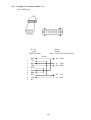
15.1 Example 1 Connection with PC-AT...................................................................................... 181
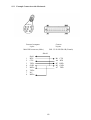
15.2 Example 2 Connection with PC-AT...................................................................................... 182
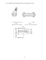
15.3 Example Connection with Macintosh ................................................................................... 183
15.4 Example of Connection Cables for Computer Side of VC-C50i .......................................... 184
5
15.5 Example of Connection Cables for Next Camera Side of VC-C50i ..................................... 185
15.6 Example of Connection Cables from VC-C50i to VC-C50i................................................. 186
16. Example of Host Control Sequence ............................................................................................... 187
16.1 Assignment of Host Control Mode ....................................................................................... 187
16.2 Initial Setting ......................................................................................................................... 188
16.3 Command Termination Notification ..................................................................................... 189
16.4 Remote Controller Through .................................................................................................. 190
16.5 Cascade ON Assignment....................................................................................................... 191
16.6 Cascade Individual Assignment ............................................................................................ 192
16.7 Cascade Global Assignment.................................................................................................. 193
6
1. Getting Started
This manual describes commands which control communication camera VC-C50i through
RS-232C interface from host computer.
Before reading this manual, it is recommended to read operation manual of VC-C50i.
CAUTION:
VC-C50i/VC-C50iR Pan/Tilt operational durability is guaranteed for 100K cycles.
In case of the continuous operation by the program such as Auto Pan Tilt system, & etc.,
it is important not to overdrive the said value (100K).
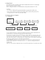
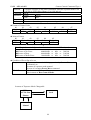
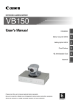
2. Connection with your Computer
2.1 Connection
HOST PC
COM Port
RS-232C cable (dedicated)
RS-232C cable (dedicated)
1st Unit
Host Computer
RS-232C cable (dedicated)
2nd Unit
VC-C50i
VC-C50i
3rd Unit
VC-C50i
Use the supplied connector to connect the COM port on the host computer with the RS-232C
terminal on the VC-C50i host side using a RS-232C dedicated cable.
For operation of multiple connected VC-C50i units, connect a RS-232C dedicated cable to the
OUT side (next camera side) of the first VC-C50i unit's RS-232C terminal and to the IN side
(host side) of the second VC-C50i unit's RS-232C terminal. Three or more units are connected in
the same way, and up to nine VC-C50i units can be connected.
If a Cascade ON command is issued when multiple VC-C50i units are connected, the device
numbers of the connected VC-C50i units are set as 1, 2, 3, and so on, starting from the host
computer side.
If the VC-C50i is used as a single unit, there is no need for connections of a second or more units.
7
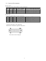
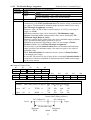
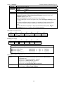
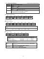
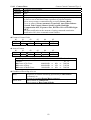
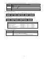
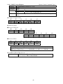
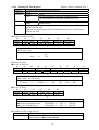
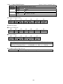
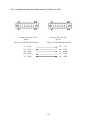
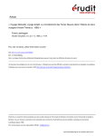
2.2
Connector & Pin Assignment
RS-232C OUT
(Connection to Next Camera Side in Cascade Connection)
A3
RTS
Output → NEXT CAMERA RS-232C cascade output send request
B3
CTS
Input NEXT CAMERA → RS-232C cascade output send permit
A4
TXD Output → NEXT CAMERA RS-232C cascade output send data
B4
RXD
Input NEXT CAMERA → RS-232C cascade output receive data
A5
GND
RS-232C cascade output GND
RS-232C IN
(Connection to Host Side in Cascade Connection)
B5
GND
A6
RTS
Output
→ Host PC
B6
CTS
Input
Host PC →
A7
TXD Output
→ Host PC
B7
RXD
Input
Host PC →
Connector model: B2L 3.5/20 LH SN OR
Manufacturer: Weidmuller (supplied with product)
Camera side connector diagram
8
RS-232C input GND
RS-232C input send request
RS-232C input send permit
RS-232C input send data
RS-232C input receive data
3. Communication Format
3.1 Signal Format
RS-232C Conformity
Connector & Pin assignment of connector are referred to 2.2
Transmission Mode
: Half Duplex (Full duplex for notification)
Transfer Speed
: 4800, 9600, 14400, 19200bps. (selected through menu window)
Data Bit
: 8 bit
Parity
: None
Stop Bit
: 1 bit or 2 bit (selected through menu window)
Handshake
: RTS/CTS Control
Synchronous Type
: Asynchronous Communication
RS-232C level Definitions
ON
: +5V to +15V
OFF
: –5V to –15V
3.2 Understanding
The followings are described based on the signal from the computer terminal (RS-232C).
• The flow is controlled by RTS/CTS terminal control.
• When the VC-C50i is ready to receive control commands, the CTS line of the computer is ON.
And as long as VC-C50i is turned on, the CTS line is always ON because VC-C50i is ready to
receive the control commands.
• In case of starting the communication from the computer, the RTS line of computer must be
ON.
• After receiving the answer corresponding to the control command, the next control commands
will be ready to transmit.
Before transmitting the answer corresponding to the control command, VC-C50i cancels the
received code, in case of receiving the next control commands.
• In case of not receiving the answer to the computer, the RTS line of the computer must be OFF.
In this case, VC-C50i will suspend to issue the answer. If VC-C50i, however, suspends more than
one second, the issue of the answer will be forced to stop and VC-C50i returns to the receiving
status.
• In case of using the notification functions, the communication format must correspond to full
duplex. There are some cases for VC-C50i to issue the notification data, while the computer
issues the commands.
• The standard waiting time of the answer is 300ms. If VC-C50i does not return the answer more
than 300ms, there must be some errors.
• Note that VC-C50i is unable to execute remote control and communication control at a one time.
After turn on, VC-C50i is under the condition of remote control. If the communication control is
required, Host Control Mode command or Cascade ON command must be issued. Note that
the VC-C50i can not shift the remote control status to the host communication control mode
during menu processing.
9
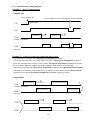
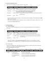
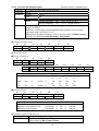
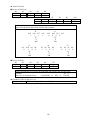
3.3 Communication Timing Diagram
Example 1: Basic communication
Computer Side
Power turned on
In case unable to receive the answer to the computer
Always ON
CTS
RTS
Command 1
execute
Command 2
execute
TXD
(Control Command)
Answer 1
Answer 2
RXD
(Answer)
Answer 2
Suspend
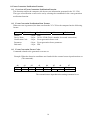
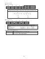
Example 2: Unable to execute the commands due to error
The details are referring to 12.1 Pan Speed Assignment command.
The followings shows the case which causes the error by Pan Speed Assignment command,
when the communication mode isn’t host mode. Pan Speed Assignment commands will cause
the error mode under the condition that the communication mode is not host mode.
After the error generated by Pan Speed Assignment command, the Operation Status Request
command is issued and confirms that the error source isn’t host mode, then the Host Control
command is issued and Pan Speed Assignment command is again executed.
Computer Side
Pan Speed Setting
Fail to execute
Operation Status Request
TXD
(Control Command)
Busy + Mode Error
Operation Status
RXD
(Answer)
Host Control Mode
Execute
Pan Speed Setting
Execute
TXD
No error (ACK)
RXD
10
No error (ACK)
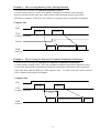
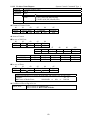
Example 3: The case using Remote Control Through Function
The details are referring to 9. Function of Remote Control.
As shown below, there are some cases that the commands and remote control through
data are generated at the same time, while remote control through function turns on the
RTS line of computer. In this case, the software of computer must correspond to full duplex.
Computer Side
RTS
Command 1
Command 2
TXD
(Control Command)
ON
Remote
Answer 1
Remote Control ON Data
Answer 2
RXD
(Answer)
Example 4: The case using the Function of Command Termination Notification
The details are referring to 6. Function of Command Termination Notification.
As shown in the example below, when the command termination notification function is used,
it is possible that both the command and command termination notification will be generated
at the same time while the RTS line of the computer is on. For this reason, the control software
of the computer must support full duplex.
Computer Side
RTS
Command 1
Command 2
TXD
(Control Command)
Execute
Answer 1
RXD
(Answer)
11
Command Termination Notification
Answer 2
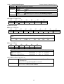
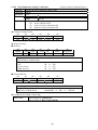
4. Control Command Format
This format is to transmit from the computer to VC-C50i.
Header
Device Num
Command
Parameter
End mark
Header
: 1 byte FFh
Device Num : 2 byte 3030h~3039h (Device number in cascade connection)
Command : 2 byte (refer to 12. Details of Pedestal Control Commands
~ 14. Details of System Control Commands)
Parameter
: Variable length If not specified, parameter manifests hexadecimal, transmits
its ASCII code.
End mark
: 1 byte EFh
Just after power on, device number is 3030 and each device number is determined by Cascade
ON control command.
The control command (Global Command) of device number 3030 became valid to all VC-C50i
connected in Cascade ON status.
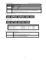
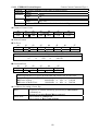
5. Answer Format
5.1 Answer Format
This answer format corresponds to the control command transmitted from the computer to
VC-C50i.
Header
Header
Device Num
Error Code
Status
End mark
Device Num
Error Code
Status
End mark
: 1 byte FEh
: 2 byte 3030h~3039h (Device number in cascade connection)
: 2 byte manifested error flag In hexadecimal and return it's ASCII code.
: Variable length If not specified, status manifests hexadecimal, transmits
its ASCII code.
: 1 byte EFh
Under the condition in Cascade Connection ON, the answer corresponding to control
command of device number 3030, is returned only to the last device connected in cascade.
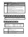
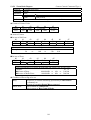
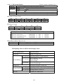
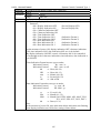
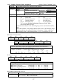
5.2 Error Code
Error code manifests error flag in hexadecimal and returns it’s ASCII code. If not exists error,
all bits of error flags are cleared and becomes zero.
• The bit assignment of error flag.
b7(MSB)
Mode error
1st byte
b6
Parameter error
b5
Command error
b7: Mode Error
b6: Parameter Error
b5: Command Error
b4: Busy
b4
b3
b2
b1
b0(LSB)
Busy
System
reservation
System
reservation
System
reservation
System error
In case of wrong mode
In case of receiving wrong parameter
In case of receiving wrong command
In case of unable to execute by error
12
2nd byte
b3: System Reservation
b2: System Reservation
b1: System Reservation
b0: System Error
Always zero
Always zero
Always zero
In case of the fatal error to the system
The details of error flags are described as below.
Busy
: VC-C50i is unable to execute the commands in process to execute the former
command.
: In case of generating Command Error, Parameter Error, Mode Error or
System Error.
Command Error
: In case of receiving the wrong commands (not prepared commands).
Parameter Error
: In case of over value of parameter or wrong parameter length.
Mode Error
: In case of receiving the command unable to execute under VC-C50i during
the receiving status.
System Error
: In case that the fatal accidents occur for some reason.
CAUTION
• If the device number is wrong, its control command code will be ignored.
• By Operation Status Request, the cause of error can be found.
• The error check will be executed by the following priority order.
(1) Mode Error
(2) Command Error
(3) Parameter Error, Busy
VC-C50i sets the error flag corresponding to any, after the detection of error, and returns
the answer, then multiple error flags can’t be set. Busy, however, is exceptional and set,
whenever any of Command Error, Parameter Error, Mode Error or System Error occurs.
Example: Wrong command to be transmitted.
b7 = 0,
1st byte
2nd byte
b6 = 0, b5 = 1, b4 = 1
b3 = 0, b2 = 0, b1 = 0,
3h → 33h
0h → 30h
(Hexadecimal indication → ASCII code conversion)
b0 = 0
Note: When the command errors occur and unable to execute, busy flag and command error flag
will be set at the 1.
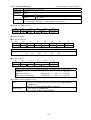
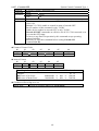
5.3 Status
In case of having received status request command, this status adds status value to the
answer. The details of Operation Status Request command and status value are described
later. (Refer to 14. Details of System Control Commands)
The Operation Status Request will accept the command, if not host control mode.
13
6. Function of Command Termination Notification
6.1 Function In General
Among the control commands of VC-C50i, the executive format type 2 has the function of
the termination notification at the time terminated to executed. (the details of executive format
refers to 10. Classification of Command) The termination notification to be admitted or
forbidden will be executed by the ON/OFF command of the termination notification.
Note 1 : After just turn on, the function of command termination notification is set under
the condition of forbidden status.
Note 2 : In case of using this function, the software of computer must correspond to full duplex,
in order to be able to receive the termination notification data, even if the computer
issues the commands.
Note 3 : The RTS line must be always ON, in order not to forbid the transmission of notification
data during the flow control.
Note 4 : The details of the communication timing are referring to 3.3 Communication Timing
Diagram.
6.2 Format of Command Termination Notification
Before the time to terminate the execution, the data format from VC-C50i to the computer is
configured as shown below.
Header
Device Num
Command Parameter
End mark
Header
: 1 byte FAh
Device Num : 2 byte 3030h~3039h (Device number in cascade connection.)
Command
: 2 byte Command at the time of the operation terminated.
Parameter
: Variable length
Parameter at the time of the operation terminated.
End mark
: 1 byte EFh
Under the status of Cascade ON, the command termination notification will be returned
from each device, corresponding to the control command of Device Num. 3030. (device number
3031~3039)
7. Cascade Global Notification
7.1 In General
In case of using VC-C50i connected in cascade, the global commands (Device number 3030h)
can execute the identical operation to all VC-C50i connected in cascade. But the only last device
will return the answer to the computer. In case of the cascade global notification function
admitted and global command issued, the only error information integrated among the answer
information of VC-C50i is notified to the computer.
Note 1 : After just turn on, the function of command termination notification is of setting the
forbidden status.
Note 2 : In case of using this function, the software of computer must correspond to full duplex,
in order to be able to receive the termination notification data, even if the computer
issues the commands.
Note 3 : The RTS line must be always ON, in order not to forbid the transmission of notification
data during the flow control.
14
Note 4 : The details of the communication timing are referring to 3.3 Communication Timing
Diagram.
7.2 Format of Cascade Global Notification Data
Before the time to terminate the execution, the data format from VC-C50i to the computer is
configured as shown below.
Header
Device Num
Notification Code
End mark
Header
: 1 byte F8h
Device Num
: 2 byte 3031h~3039h (Last device number connected in cascade.)
Notification Code : 4 byte Present information of VC-C50i connected.
End mark
: 1 byte EFh
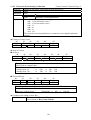
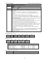
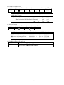
7.3 Notification Code
The error information of VC-C50i connected in cascade indicates in hexadecimal, returns its
ASCII code. If the error does not exists, all bits of notification flags will be cleared and become
zero.
• Bit Assignment of Error Flags.
b15(MSB)
b14
b13
b12
b11
b10
b9
System Resv.(0)
System Resv.(0)
System Resv.(0)
System Resv.(0)
System Resv.(0)
System Resv.(0)
b7
b6
b5
b4
b3
b2
Cascade 8
th
Cascade 7
th
Cascade 6
th
Cascade 5
th
Cascade 4
th
Cascade 3
b8
System Resv.(0)
b1
rd
Cascade 9th
b0(LSB)
Cascade 2
nd
Cascade 1st
Example: 6 units are connected in cascade, and the errors occur in 1st unit and 5th unit.
b15 = 0,
b7 = 0,
1st byte
2nd byte
b14 = 0, b13 = 0, b12 = 0
b11 = 0, b10 = 0, b9 = 0,
0h → 30h
0h → 30h
(Hexadecimal indication → ASCII code conversion)
3rd byte
4th byte
b6 = 0, b5 = 0, b4 = 1
b3 = 0, b2 = 0, b1 = 0,
1h → 31h
1h → 31h
(Hexadecimal indication → ASCII code conversion)
Example of Notification data
d0
d1
d2
Header
Device Num
F8h
30h
36h
d3
30h
d4
d5
Notification Code
30h
31h
15
d6
31h
b8 = 0
b0 = 1
d7
End mark
EFh
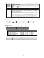
8. Event Generation Notification Function
8.1 Overview of Event Generation Notification Function
This function notifies the computer side about event information generated in the VC-C50i.
The types of notification events can be set by selecting the commands for the event generation
notification function.
8.2 Event Generation Notification Data Format
When an event is generated, the data sent from the VC-C50i to the computer has the following
format.
Header
Device Num
Header
: 1 byte
Device Num
: 2 byte
Notification Code : 2 byte
Parameter
: 2 byte
End mark
: 1 byte
End mark
Notification Code
Parameter
FBh
3031h~3039h (Device number in cascade connection.)
Event generation factor code.
Event generation factor parameter.
EFh
8.3 Event Generation Factor Codes
Commands related to the generated event are set.
Example: When the detection conditions are found with the external sensor input detection set
(74h command) .
d0
Header
FBh
d1
d2
Device Num
30h
3Xh
d3
d4
d5
d6
d7
Notification Code
Parameter
End mark
00h
74h
30h
30h
EFh
⇑
The external sensor input detection setting command is set.
16
9. Function of Remote Control
9.1 In General
The ON/OFF status of remote control can be monitored by the computer.
By Remote Control Through command ON, VC-C50i is in the status of through mode and
notify the status of ON/OFF to the computer.
If the control mode is set to remote through ON by host control, the VC-C50i sends the status
corresponding to the pressed key directly to the computer side without performing any operation
for any received remote control code. If the control mode is set to remote through ON by
remote control, the VC-C50i performs the operation corresponding to the received remote control
code, and then sends the status to the computer side.
Note 1 : After just turn on, the function of remote control is of setting the status OFF.
Note 2 : In case of using this function, the software of computer must correspond to full duplex,
in order to be able to receive the remote control through data, even if the computer issues
the commands.
Note 3 : The RTS line must be always ON, in order not to forbid the remote control through data
during the flow control.
Note 4 : The details of the communication timing are referring to 3.3 Communication Timing
Diagram.
9.2 Data Format of Remote Control Through
At the time to receive remote control data, the data format from VC-C50i to the computer is
configured as shown below.
Header
Header
Device Num
Status
End mark
: 1 byte FDh Remote Button ON (Pushed)
FCh Remote Button OFF (Released)
Device Num : 2 byte 3030h~3039h (Device number in cascade connection.)
Status
: 2 byte Remote control code indicates hexadecimal, returns its ASCII code.
(refer to 9.3. Table of Remote Control Code)
End mark
: 1 byte EFh
Each device return the data of remote control in the status of cascade connection (3031~3039).
Example: Remote Control Button [1] ON
d0
d1
d2
Header
Device Num
FDh
30h
3Xh
d3
d4
d7
Remote control Code End mark
30h
31h
EFh
Example: Remote Control Button [1] OFF
d0
d1
d2
Header
Device Num
FCh
30h
3Xh
d3
d4
d7
Remote control Code End mark
30h
31h
EFh
17
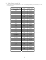
9.3 Table of Remote Control Code
At the remote control through mode, the code corresponding to the key transmitted by VC-C50i,
is described below.
Command of remote control
(Remote Key)
MF
1
2
3
4
5
6
AF
NEAR
FAR
WIDE
TELE
UP
DOWN
LEFT
RIGHT
HOME
ID
BRIGHTON SCREEN
CAMERA
SET/OK
CANCEL
*
#
BRIGHT+
Fn
MENU
7
8
9
0
Code
Status Value
00h
01h
02h
03h
04h
05h
06h
07h
08h
09h
0Ah
0Bh
0Ch
0Dh
0Eh
0Fh
10h
11h
12h
13h
14h
15h
16h
17h
18h
19h
1Ah
1Bh
1Ch
1Dh
1Eh
1Fh
30 30h
30 31h
30 32h
30 33h
30 34h
30 35h
30 36h
30 37h
30 38h
30 39h
30 41h
30 42h
30 43h
30 44h
30 45h
30 46h
31 30h
31 31h
31 32h
31 33h
31 34h
31 35h
31 36h
31 37h
31 38h
31 39h
31 41h
31 42h
31 43h
31 44h
31 45h
31 46h
18
10. Classification of Command
10.1 Classification by Operation
VC-C50i consists of pedestal and camera sections, and command consists of Pedestal Control,
Camera Control and System Control. This manual describes according to this classification.
(1) Pedestal Control
This control is to set each parameter, to inquire and to indicate operation for pedestal.
Pan Speed Assignment, Pan Speed Request, Pan Angle Request, etc. are counted
among this classification. See the table 11.1 Pedestal Control Command Table,
and 12. Details of Pedestal Control Commands.
(2) Camera Control
This control is to set each parameter, to inquire and to indicate operation for camera.
Zoom Position Request, Parameter Setting, etc.. are counted among this classification.
See the Table 11.2 Camera Control Command Table, and 13. Details of Camera
Control Commands.
(3) System Control
This control is to control the operation by remote control, to control LED display, operation
of both camera and pedestal, to inquire the inside status and etc.
Remote ON/OFF, LED Forced Control, Preset Setting, Status Request of Operation are
counted among this classification.
See the table 11.3 System Control Command Table, and 14. Details of System Control
Commands.
10.2 Classification by Executive Format
Each command classify as one of Synchronous Execution (type 1) and other of Non-Synchronous
Execution A (type 2).
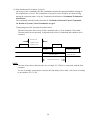
(1) Synchronous Execution (type 1)
This command executes immediately at the time of command receipt, and complete the
execution at the time of the answer completed.
The command among this classification enable to accept the next command at the moment of
answer transmission. This classified commands describe as type 1 in 12. Detail of Pedestal
Control Commands ~ 14. Details of System Control Commands.
Timing diagram describes below.
The answering time after receipt of the command code is 10 ms in standard, and 30 ms Max.
And the execution completes at the beginning of transmission.
Execution completed
T1(TYPE): 10ms
Command 1
T1(MAX): 30ms
Command 2
Answer 1
19
(2) Non-Synchronous Execution A (type 2)
On receipt of the command code, this command transmits the command without waiting of
the completion to execute. The completion of operation can be found by the status of flag
among the operation status, or by the Termination Notification of Command Termination
Notification.
The commands classified in this, describe in 12. Details of Pedestal Control Command ~
14. Details of System Control Commands as type 2.
Timing diagram of the operation describes below.
The answering time after receipt of the command code, is 10 ms standard, 30 ms Max.
The time between start and stop, is depend on the class of commands and condition to be
executed.
Operation start
T1(TYPE): 10ms
Command 1
T1(MAX): 30ms
Command 2
Answer 1
Command completed
Operation status
(Command Termination
Notification ON)
Completion of Execution
NOTE
The time shown above indicates the case of single VC-C50i to be connected with the host
computer.
In case of multiple connection in cascade, the time delay (30 ms Max.) will occur according
to the number of VC-C50i.
20
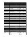
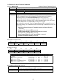
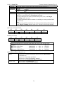
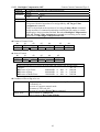
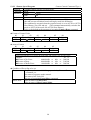
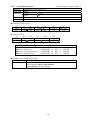
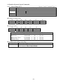
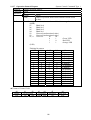
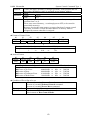
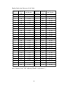
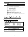
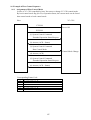
11. Control Command Table
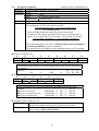
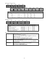
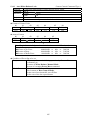
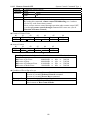
11.1
Pedestal Control Command Table
Function
Meaning
Command
Parameter
Status
Ref
Pan Speed Assignment
To set running speed for Pan
0050h
008h~320h
None
P 26
Tilt Speed Assignment
To set running speed for Tilt
0051h
008h~26Eh
None
P 27
Pan Speed Request
To return present running speed for Pan
0052h
0h
008h~320h
P 28
Tilt Speed Request
To return present running speed for Tilt
0052h
1h
008h~26Eh
P 29
Pan Tilt Stop
To stop running of Pan/Tilt
0053h
0h
None
P 30
Pan Right Start
To start Pan running to right
0053h
1h
None
P 31
Pan Left Start
To start Pan running to left
0053h
2h
None
P 32
Tilt Up Start
To start Tilt running to up
0053h
3h
None
P 33
Tilt Down Start
To start Tilt running to down
0053h
4h
None
P 34
Home Position
To move Home position
0057h
None
None
P 35
Pedestal Initialize 1
After Initialization, to move home position
0058h
0h
None
P 36
Pedestal Initialize 2
After Initialized, to move the origin position
0058h
1h
None
P 37
Pan Slowest Speed Request
To return the slowest speed of Pan
0059h
0h
008h
P 38
Pan Fastest Speed Request
To return the fastest speed of Pan
0059h
1h
320h
P 39
Tilt Slowest Speed request
To return the slowest speed for Tilt
0059h
2h
008h
P 40
Tilt Fastest Speed request
To return the fastest speed for Tilt
0059h
3h
26Eh
P 41
Pan Angle Pulse Ratio Request
To return coefficient of Pan angle conversion
005Bh
0h
2BF2h
P 42
Tilt Angle Pulse Ratio Request
To return coefficient of Tilt angle conversion
005Bh
1h
2BF2h
P 43
Pan Minimum Angle Request
To return minimum angle of Pan
005Ch
0h
7C87h (7A19h) P 44
Pan Maximum Angle Request
To return maximum angle of Pan
005Ch
1h
8379h (85E7h)
Tilt Minimum Angle Request
To return minimum angle of Tilt
005Ch
2h
7EF5h (7CE0h) P 46
Tilt Maximum Angle Request
To return maximum angle of Tilt
005Ch
3h
8320h (8059h)
P 47
Pan/Tilt Stop
To stop Pan/tilt running
0060h
00h
None
P 48
Pan/Tilt Start Stop
To start and stop Pan/tilt running
0060h
01h~22h
None
P 49
Pan/Tilt Angle Assignment
To move assign position of Pan/Tilt
0062h
XXXX, YYYYh
None
P 51
Pan/Tilt Angle Request
To return present position of Pan/Tilt
0063h
None
Pan Movable Range Assignment
To assign movable limit for Pan
0064h
0h, PMIN, PMAX
None
P 55
Tilt Movable Range Assignment
To assign movable limit for Tilt
0064h
1h, TMIN, TMAX
None
P 57
Pan Movable Range Request
To return present position of Pan
0065h
0h
PMIN, PMAX
P 59
Tilt Movable Range Request
To return present position of Tilt
0065h
1h
TMIN, TMAX
P 60
XXXX, YYYYh P 53
Note: XXXX, YYYY means Pan angel, Tilt angle in hexadecimal.
PMIN, PMAX means Pan min. movable range, max. movable range in hexadecimal.
TMIN, TMAX means Tilt mini. movable range, max. movable range in hexadecimal.
The value inside ( ) means status value in the inverse mount type.
21
P 45
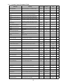
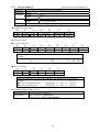
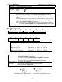
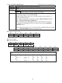
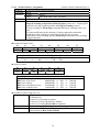
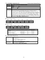
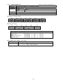
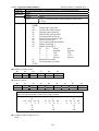
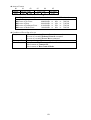
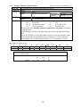
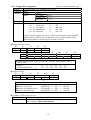
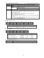
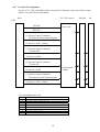
11.2
Camera Control Command Table
Function
Command
Parameter
Status
00A0h
00A0h
00A1h
00A1h
00A1h
00A1h
00B0h
00B1h
00B1h
00B1h
00A2h
00A2h
00A2h
00A2h
00A2h
00A3h
00A4h
00B3h
00B4h
00B4h
00B4h
00B4h
00A5h
00A5h
00A5h
0h
1h
0h
1h
2h
3h
XXXXh *1
0h
1h
2h
0h
1h
2h
3h
4h
00h~80h
None
0000h~07A6h
0h
“31h”, 0h~7h
2h
3h
0h
1h
2h
None
None
None
None
None
None
None
XXXXh *1
None
XXXXXXXXh *2
None
None
None
None
None
None
00h~80h
None
0000h~07A6h
None
30h~37h
07A6h
None
None
None
P 61
P 62
P 63
P 64
P 65
P 66
P 67
P 68
P 69
P 70
P 71
P 72
P 73
P 74
P 75
P 76
P 77
P 78
P 79
P 80
P 81
P 82
P 83
P 84
P 85
00A5h
“40h”
None
P 86
Exposure Manual
AE Lock OFF
AE Lock ON
Shutter Speed Program
Shutter Speed 1/60 (PAL: 1/50)
To turn OFF power for Camera section
To turn ON power for Camera section
To change mode of focus to AF
To stop and change of focus to Manual
To move to near focus
To move to far focus
To move to focus position assigned
To return present focus position
After adjustment of focus, change to MF
To return movable range of focus
To stop zoom operation
To zooming to wide
To zooming to tele
To zooming to wide high speed
To zooming to tele high speed
To move to zoom position assigned
To return present zoom position
To move to zoom position assigned
To return present zoom position
To assign running speed of zoom
To return present running speed
To return maximum movable position
To eliminate compensation of backlight
To compensate backlight
To control exposure automatically
To reduce the shutter speed to low
automatically
To control exposure manually
To cancel AE lock ON
To lock the exposure of AE mode
To change shutter speed to program mode
To change shutter speed to 1/60 (PAL: 1/50)
00A5h
00A5h
00A5h
00A8h
00A8h
3h
40h
41h
0h
1h
None
None
None
None
None
P 87
P 88
P 89
P 90
P 91
Shutter Speed1/100 (PAL: 1/120)
To change shutter speed to 1/100 (0PAL: 1/120)
00A8h
2h
None
P 92
None
P 93
Camera OFF
Camera ON
Focus Auto
Focus Manual
Focus Near
Focus Far
Focus Position Assignment
Focus Position Request
One Push AF
Focus Range Request
Zoom Stop
Zoom Wide
Zoom Tele
Zoom Hi Wide
Zoom Hi Tele
Zoom Position 1 Assignment
Zoom Position 1 Request
Zoom Position 2 Assignment
Zoom Position 2 Request
Zoom Speed Assignment
Zoom Speed Request
Zoom Maximum Request
Backlight Compensation OFF
Backlight Compensation ON
Exposure Auto
Exposure Mode Auto Slow Shutter
Meaning
Shutter Speed Assignment
To assign shutter speed
00A5h
“35h”, 00h~1Bh
80h~83h
Shutter Speed Request
To return present shutter speed
00A5h
6h
AGC Gain Assignment
AGC Gain Request
Iris Assignment
Iris Request
AE Target Value Assignment
AE Target Value Request
Auto White Balance Normal
Auto White Balance Lock
White Balance Manual Mode
White Balance Value Assignment
White Balance Value Request
Fade Normal
Fade White
Fade Hi Speed White
Fade Hi Speed Black
Camera Reset
Zoom Ratio request
Pixel Size Request
To assign AGC Gain
To return present AGC gain
To assign iris
To return iris value
To assign target value of AE brightness
To return target value of AE brightness
To adjust white balance automatically
To stop white balance control
To set white balance manually
To assign white balance manually
To return present white balance manually
To fade out normal image slowly
To fade in white image slowly
To change to white image high speed
To change to black image high speed
To reset Camera section
To return zoom ratio of camera
To return CCD pixel size
Sets the status when infrared cut filter is
inserted
Sets the status when infrared cut filter is not
inserted.
Returns the setting status of the infrared cut
filter.
Sets the electronic zoom to the designated
magnification.
00A5h
00A5h
00A5h
00A5h
00A5h
00A5h
00A7h
00A7h
00A7h
00A7h
00A7h
00A9h
00A9h
00A9h
00A9h
00AAh
00ABh
00ACh
Insertion of Infrared Cut Filter
Settings when Infrared Cut Filter
Not Inserted
Infrared Cut Filter Status Request
Electronic Zoom Setting
22
Ref
“37h”, 00h~FFh
8h
“39h”, 02h~11h
“3Ah”
“3Bh”, 10h~FFh
“3Ch”
0h
1h
2h
“34h”, 00h~FFh
5h
0h
1h
2h
3h
None
None
None
00h~1Bh
80h~83h
None
00h~FFh
None
00h~12h
None
10h~FFh
None
None
None
None
00h~FFh
None
None
None
None
None
1Ah
14h
P 97
P 98
P 99
P 100
P 102
P 103
P 104
P 105
P 106
P 107
P 108
P 109
P 110
P 111
P 112
P 113
P 114
P 115
00B5h
1h
None
P 116
00B5h
0h
None
P 117
00B6h
None
0h or 2h
P 118
00B7h
2 byte
(magnification)
None
P 119
P 95
Electronic Zoom Setting
Verification
Noise Reduction OFF
Noise Reduction Low Level ON
Noise Reduction High Level ON
Noise Reduction Setting
Verification
Dome Mode Setting
Dome Mode Setting Verification
Product Version Request
EEPROM Version Request
Returns the electronic zoom magnification that
was set.
Sets the noise reduction to OFF.
Sets the noise reduction to low level ON.
Sets the noise reduction to high level ON.
00B8h
None
00b9h
00B9h
00B9h
0h
1h
2h
2 byte
(magnification)
None
None
None
Returns the noise reduction setting value.
00BAh
None
0h~2h
P 124
Sets the Dome mode to the designated value.
Returns the Dome mode setting value.
To return version value of camera section
to return version of camera EEPROM
00BDh
00BDh
00BEh
00BEh
0000h or 0001h
01h
0h
1h
None
00h~01h
00h~FFh
00h~FFh
P 125
P 126
P 128
P 129
*1 4 figures hexadecimal value within the request of focus limit.
*2 The focus range changes according to the zoom position. The value indicates Max/Min 4 figures in hexadecimal.
23
P 120
P 121
P 122
P 123
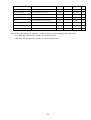
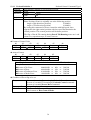
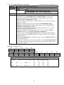
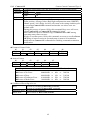
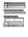
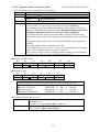
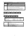
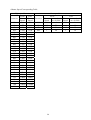
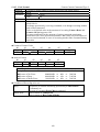
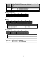
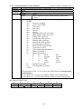
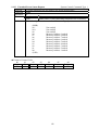
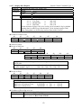
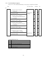
11.3
System Control Command Table
Function
Meaning
Command
Parameter
Status
Ref
Alarm Output OFF
Sets the alarm output (+/- terminal) to Open.
0072h
0h
None
P 130
Alarm Output ON
Sets the alarm output (+/- terminal) to Closed.
0072h
1h
None
P 131
Alarm Output Status Request
Returns the alarm output setting status.
0073h
None
0h or 1h
P 132
External sensor input detection disabled
0074h
00h
None
P 133
0074h
01h
None
0074h
10h
None
0074h
11h
None
Returns external sensor input detection status.
0075h
None
0h or 1h
P 134
Returns the external sensor input detection
setting status.
0075h
0h
00h or 01h or
10h or 11h
P 135
Sets the internal infrared light ON/OFF control.
0076h
0h~6h
None
P 136
0077h
None
1 byte
P 137
0078h
0h
None
P 138
0078h
1h
None
P 139
0079h
None
1 byte
P 140
External Sensor Input Detection
Setting
External Sensor Input Detection
Setting
External Sensor Input Detection
Setting
External Sensor Input Detection
Setting
External Sensor Input Detection
Status Request
External Sensor Input Detection
Setting Information Request
Internal Infrared Light ON/OFF
Control
Internal Infrared Light Status
Request
External sensor input detection enabled with
notification of changes from Closed to Open
External sensor input detection enabled with
notification of changes from Open to Closed
External sensor input detection enabled with
notification of changes from Closed to Open and
notification of changes from Open to Closed
P 133
P 133
P 133
External Light Output Status
Request
Returns the internal infrared light ON/OFF
setting status.
Sets the external light output (+/- terminal) to
Open.
Sets the external light output (+/- terminal) to
Closed.
Returns the setting status of the external light
output terminal.
Remote Control ON
To available remote controller
0080h
0h
None
P 141
Remote Control OFF
To inhibited remote controller
0080h
1h
None
P 142
Operation Status Request
To return information of operate status
0086h
None
3 byte
P 143
Extended Operation Status Request To return extended information of operate status
0086h
0h
5 byte
P 144
Operation Status 3 Request
To return information of operate status 3
0086h
1h
4 byte
P 146
Operation Status 4 Request
To return information of operate status 4
0086h
2h
2 byte
P 148
P 150
External Light Output OFF
External Light Output ON
Product Name Request
To return product name
0087h
None
"C50i" or
"C50iR"
ROM Version Request
To return ROM version of VC-C4
0088h
None
"Vx-xx"
P 151
Preset Set
To memory preset position
0089h
1h~9h
None
P 152
Preset Move
To move preset position
008Ah
1h~9h
None
P 153
Preset Status Request
To request preset status
008Bh
None
2 byte
P 155
Extended Preset Status Request
To request extended preset status
008Bh
0h
3 byte
P 156
Remote Controller Through Setting To set ON/OFF of remote controller through
008Dh
0h~1h
None
P 158
LED Normal Display
To set normal display of LED
008Eh
0h
None
P 159
LED Forced Control
To set forced ON/OFF of LED
008Eh
1h~4h
None
P 160
Cascade OFF
To release cascade connection OFF
008Fh
0h
None
P 161
Cascade ON
To connect cascade connection ON
008Fh
1h
None
P 162
Host Control Mode
To control by host computer
0090h
0h
None
P 163
Local Control Mode
To control by remote controller
0090h
1h
None
P 164
Screen Control
To set screen display of date, time, characters
0091h
00h~09h
None
P 165
Display Character Data Assignment To assign character data of display
0091h
1h XX,Y,DD
None
P 167
Display Character Data Request
To request character data of display
0091h
2h XX,Y
2 byte
P 169
Display Date Setting
To set display date (yy/mm/dd)
0091h
3h YY,MM,DD
None
P 171
24
Display Date Request
To request display date (yy/mm/dd)
0091h
4h
YY,MM,DD
P 172
Display Time Setting
To set display time (hh/mm/ss)
0091h
5h,HH,MM,SS
None
P 173
Display Time Request
To request display time (hh/mm/ss)
0091h
6h
HH,MM,SS
P 174
Turning On Time Request
To request total accumulated turn on time
0092h
0h~1h
0000h~FFFFh
P 175
Default Setting
To initialize in status of factory setting
0093h
None
None
P 176
Command Termination Notification
To set termination notification ON/OFF
Setting
0094h
0h~1h
None
P 177
Global Notification Setting
To set global notification ON/OFF
0095h
0h~1h
None
P 178
Pedestal Model Request
To return pedestal model (normal/inverse)
009Ah
0h
0h or 1h
P 179
Camera Model Request
To return camera model (NTSC/PAL)
009Ah
1h
0h or 1h
P 180
Note: XX, Y, DD indicate X address, Y address, character data of display in hexadecimal
YY, MM, DD indicate year, month, day in hexadecimal.
HH, MM, SS indicate hour, minute, second in hexadecimal.
25
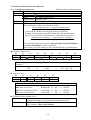
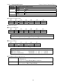
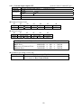
12. Details of Pedestal Control Commands
12.1 Pan Speed Assignment
Pedestal Control Command Type 1
Function
To set running speed of Pan direction.
Command 0050h
Parameter Length
3 byte
Range
8~800PPS (008h~320h)
Default Value 800PPS (320h)
Status
None
Reference •1LSB of parameter value is equal to 0.1125 degree/s
•The running time of Pan can calculate as under
(Pan position after run) – (Pan position before run)
(Pan running speed)
(refer to 12.27, 12.29 concerning Pan position of pedestal)
Example set Pan running speed 800. In this case, the running time is
approx. 2 seconds from +800 position to –800 position of pedestal.
800{position +90 degree} – (–800){position –90 degree}
800{Pan running speed}
•The command unable to set speed, is Home Position, Pedestal Initialize 1
and Pedestal Initialize 2, total 3 commands.
•Pan running speed can modify by this command during even running Pan.
Format of Control Code
d0
d1
d2
Header
Device Num
FFh
30h
3Xh
d3
d4
d5
d6
d7
d8
Command
Parameter
End mark
00h
50h
p0
p1
p2
EFh
⇓
The running speed indicates in 3 figures hexadecimal, and its ASCII code treats as
parameter.
Example:
p0
p1
p2
150
⇒
096h
⇒
30h 39h 36h
Answer Format
d0
d1
d2
Header
Device Num
FFh
30h
3Xh
d3
d4
d5
Error Code
End mark
e0
e1
EFh
⇓
Error Flag indicates in 2 figures hexadecimal and returns ASCII code value.
Example:
e0 e1
In case of No Error :
00000000B ⇒ 00h ⇒ 30h 30h
In case of Parameter Error :
01010000B ⇒ 50h ⇒ 35h 30h
In case of Mode Error :
10010000B ⇒ 90h ⇒ 39h 30h
Condition of Error flag to be set
Parameter Error •Assigned parameter comes out less than minimum value.
•Assigned parameter comes out more than maximum value.
Mode Error
•Not in status of Camera ON.
•Not in status of Host Control Mode.
26
12.2 Tilt Speed Assignment
Pedestal Control Command Type 1
Function
To set the running speed of Tilt direction.
Command 0051h
Parameter Length
3 byte
Range
8~6222PPS (008h~26Eh)
Default Value 622PPS (26Eh)
Status
None
Reference •1LSB of parameter value is equal to 0.1125 degree/s
•The running time of Tile can calculate as under
(Tilt position after run) – (Tilt position before run)
(Tilt running speed)
(refer to 12.28, 12.30 concerning Tilt position of pedestal)
Example set Tilt running speed 600. In this case, the running time is
approx. 0.9 seconds from +267 position to –267 position of pedestal.
267{position +30 degree} – (–267){position –30 degree}
600{Tilt running speed}
•The command unable to set speed, is Home Position, Pedestal Initialize 1
and Pedestal Initialize 2, total 3 commands.
•Tilt running speed can modify by this command during even Tilt running.
Format of Control Code
d0
d1
d2
Header
Device Num
FFh
30h
3Xh
d3
d4
d5
d6
d7
d8
Command
Parameter
End mark
00h
51h
p0
p1
p2
EFh
⇓
The running speed indicates in 3 figures hexadecimal, and its ASCII code treats
as parameter.
Example:
p0
p1
p2
350
⇒
15Eh
⇒
31h 35h 45h
Answer Format
d0
d1
d2
d3
d4
d5
Header
Device Num
Error Code
End mark
FFh
30h
3Xh
e0
e1
EFh
⇓
Error Flag indicates in 2 figures hexadecimal and returns ASCII code value.
Example:
e0 e1
In case of No Error :
00000000B ⇒ 00h ⇒ 30h 30h
In case of Parameter Error :
01010000B ⇒ 50h ⇒ 35h 30h
In case of Mode Error :
10010000B ⇒ 90h ⇒ 39h 30h
Condition of Error flag to be set
Parameter Error •Assigned parameter comes out less than minimum value.
•Assigned parameter comes out more than maximum value.
Mode Error
•Not in status of Camera ON.
•Not in status of Host Control Mode.
27
12.3 Pan Speed Request
Pedestal Control Command Type 1
Function
To request the running speed of Pan direction.
Command 0052h
Parameter Length
1 byte
Value
0h
Status
Length
3 byte
Range
8~800 (008h~320h)
Reference •1 LSB of status value is equal to 0.1125 degree/s.
Format of Control Code
d0
d1
d2
Header
Device Num
FFh
30h
3Xh
d3
d4
Command
00h
52h
d5
Parameter
30h
d6
End mark
EFh
Answer Format
In case of No Error
d0
d1
d2
Header
Device Num
FEh
30h
3Xh
d3
d4
d5
d6
d7
d8
Error Code
Status
End mark
30h
30h
s0
s1
s2
EFh
⇓
The running speed indicates in 3 figures hexadecimal, and its ASCII code treats
as status.
Example:
s0
s1
s2
150
⇒
096h
⇒
30h 39h 36h
In case of Error
d0
d1
d2
Header
Device Num
FEh
30h
3Xh
d3
d4
d5
Error Code
End mark
e0
e1
EFh
⇓
Error Flag indicates in 2 figures hexadecimal and returns ASCII code value.
Example:
e0 e1
In case of Parameter Error :
01010000B ⇒ 50h ⇒ 35h 30h
In case of Mode Error :
10010000B ⇒ 90h ⇒ 39h 30h
Condition of Error flag to be set
Parameter Error •Assign illegal parameters.
Mode Error
•Not in status of Camera ON.
•Not in status of Host Control Mode.
28
12.4 Tilt Speed Request
Pedestal Control Command Type 1
Function
To request the running speed of Tilt direction.
Command 0052h
Parameter Length
1 byte
Value
1h
Status
Length
3 byte
Range
8~622 (008h~26Eh)
Reference •1 LSB of status value is equal to 0.1125 degree/s.
Format of Control Code
d0
d1
d2
Header
Device Num
FFh
30h
3Xh
d3
d4
Command
00h
52h
d5
Parameter
31h
d6
End mark
EFh
Answer Format
In case of No Error
d0
d1
d2
Header
Device Num
FEh
30h
3Xh
d3
d4
d5
d6
d7
d8
Error Code
Status
End mark
30h
30h
s0
s1
s2
EFh
⇓
The running speed indicates in 3 figures hexadecimal, and its ASCII code treats
as status.
Example:
s0
s1
s2
350
⇒
15Eh
⇒
31h 35h 45h
In case of Error
d0
d1
d2
Header
Device Num
FEh
30h
3Xh
d3
d4
d5
Error Code
End mark
e0
e1
EFh
⇓
Error Flag indicates in 2 figures hexadecimal and returns ASCII code value.
Example:
e0 e1
In case of Parameter Error :
01010000B ⇒ 50h ⇒ 35h 30h
In case of Mode Error :
10010000B ⇒ 90h ⇒ 39h 30h
Condition of Error flag to be set
Parameter Error •Assign illegal parameters.
Mode Error
•Not in status of Camera ON.
•Not in status of Host Control Mode.
29
12.5 Pan Tilt Stop
Pedestal control Command Type 1
Function
To stop the running of Pan/Tilt.
Command 0053h
Parameter Length
1 byte
Value
0h
Status
None
Reference •To stop the running of Pan/Tilt except the running by Pedestal Initialize 1
and Pedestal Initialize 2 commands.
•By issuing this command, the Panning flag and Tilting flag to clear.
•By issuing this command, the Command Termination Notification flag to
clear.
Format of Control Code
d0
d1
d2
Header
Device Num
FFh
30h
3Xh
d3
d4
Command
00h
53h
d5
Parameter
30h
d6
End mark
EFh
Answer Format
d0
d1
d2
Header
Device Num
EFh
30h
3Xh
d3
d4
d5
Error Code
End mark
e0
e1
EFh
⇓
Error Flag indicates in 2 figures hexadecimal and returns ASCII code value.
Example:
e0 e1
In case of No Error :
00000000B ⇒ 00h ⇒ 30h 30h
In case of Busy :
00010000B ⇒ 10h ⇒ 31h 30h
In case of Parameter Error :
01010000B ⇒ 50h ⇒ 35h 30h
In case of Mode Error :
10010000B ⇒ 90h ⇒ 39h 30h
Condition of Error flag to be set
Busy
•In case of executing Pedestal Initialize 1 and Pedestal Initialize
2 commands.
Parameter Error •Assign illegal parameters.
Mode Error
•Not in status of Camera ON.
•Not in status of Host Control Mode.
30
12.6 Pan Right Start
Pedestal Control Command Type 2
Function
To start Pan running to the right.
Command 0053h
Parameter Length
1 byte
Value
1h
Status
None
Reference •Until Pan Tilt Stop command issues, or right limit position, continue to run.
•The running speed is able to set by Pan Speed Assignment command.
•By issuing this command, 1 is set in Panning flag among the operating
status.
The setting flag will be done, just before running pedestal. When pedestal
reaches to the right limit, Pan running will stop and clear Panning flag
and 1 of Pan Limit Position flag will be set.
Note: After power ON, at the moment of receipt of this command without
executing Pedestal Initialize 1 or Pedestal Initialize 2, returns mode
error and executes Pedestal Initialize 2.
Format of Control Code
d0
d1
d2
Header
Device Num
FFh
30h
3Xh
d3
d4
Command
00h
53h
d5
Parameter
31h
d6
End mark
EFh
Answer Format
d0
d1
d2
Header
Device Num
EFh
30h
3Xh
d3
d4
d5
Error Code
End mark
e0
e1
EFh
⇓
Error Flag indicates in 2 figures hexadecimal and returns ASCII code value.
Example:
e0 e1
In case of No Error :
00000000B ⇒ 00h ⇒ 30h 30h
In case of Busy :
00010000B ⇒ 10h ⇒ 31h 30h
In case of Parameter Error :
01010000B ⇒ 50h ⇒ 35h 30h
In case of Mode Error :
10010000B ⇒ 90h ⇒ 39h 30h
Condition of Error flag to be set
Busy
•In case of executing Home Position, Pedestal Initialize 1 and
Pedestal Initialize 2 commands.
•In case of executing Pan/Tilt Angle Assignment and Preset
Move commands.
•Executing Pan running by Pedestal Control command.
Parameter Error •Assign illegal parameters.
Mode Error
•After power ON, not executed pedestal initialize.
•Not in status of Camera ON.
•Not in status of Host Control Mode.
Normal Mounting: Right direction
Inverse Mounting: Right direction
31
12.7 Pan Left Start
Pedestal Control Command Type 2
Function
To start Pan running to the left.
Command 0053h
Parameter Length
1 byte
Value
2h
Status
None
Reference •Until Pan/Tilt Stop command issues, or reaches to the left limit, continue to
run.
•The running speed is able to set by Pan Speed Assignment command.
•By issuing this command, 1 is set in Pan running flag among the running
status.
The setting flag will be done, just before running pedestal. When pedestal
reaches to the left limit, Pan running will stop and clear Pan running flag
and 1 of Pan Limit Position will be set.
Note: After power ON, at the moment of receipt of this command without
executing Pedestal Initialize 1 or Pedestal Initialize 2, returns mode
error and executes Pedestal Initialize 2.
Format of Control Code
d0
d1
d2
Header
Device Num
FFh
30h
3Xh
d3
d4
Command
00h
53h
d5
Parameter
32h
d6
End mark
EFh
Answer Format
d0
d1
d2
Header
Device Num
EFh
30h
3Xh
d3
d4
d5
Error Code
End mark
e0
e1
EFh
⇓
Error Flag indicates in 2 figures hexadecimal and returns ASCII code value.
Example:
e0 e1
In case of No Error :
00000000B ⇒ 00h ⇒ 30h 30h
In case of Busy :
00010000B ⇒ 10h ⇒ 31h 30h
In case of Parameter Error :
01010000B ⇒ 50h ⇒ 35h 30h
In case of Mode Error :
10010000B ⇒ 90h ⇒ 39h 30h
Condition of Error flag to be set
Busy
•In case of executing Home Position, Pedestal Initialize 1 and
Pedestal Initialize 2 commands.
•In case of executing Pan/Tilt Angle Assignment and Preset
Move commands.
•Executing Pan running by Pedestal Control command.
Parameter Error •Assign illegal parameters.
Mode Error
•After turn ON, pedestal initialize has never been done.
•Not in status of Camera ON.
•Not in status of Host Control Mode.
Normal Mounting: Left direction
Inverse Mounting: Left direction
32
12.8 Tilt Up Start
Pedestal Control Command Type 2
Function
To start Tilt running to the up.
Command 0053h
Parameter Length
1 byte
Value
3h
Status
None
Reference •Until Pan/Tilt Stop command issues, or reaches to the upper limit, continue
to run.
•The running speed is able to set by Tilt Speed Assignment command.
•By issuing this command, 1 is set in Tilt running flag among the running
status.
The setting flag will be done, just before running pedestal. When pedestal
reaches to the upper limit, Tilt running will stop and clear Tilt Running flag
and 1 of Tilt Limit Position will be set.
Note: After power ON, at the moment of receipt of this command without
executing Pedestal Initialize 1 or Pedestal Initialize 2, returns mode
error and executes Pedestal Initialize 2.
Format of Control Code
d0
d1
d2
Header
Device Num
FFh
30h
3Xh
d3
d4
Command
00h
53h
d5
Parameter
33h
d6
End mark
EFh
Answer Format
d0
d1
d2
Header
Device Num
EFh
30h
3Xh
d3
d4
d5
Error Code
End mark
e0
e1
EFh
⇓
Error Flag indicates in 2 figures hexadecimal and returns ASCII code value.
Example:
e0 e1
In case of No Error :
00000000B ⇒ 00h ⇒ 30h 30h
In case of Busy :
00010000B ⇒ 10h ⇒ 31h 30h
In case of Parameter Error :
01010000B ⇒ 50h ⇒ 35h 30h
In case of Mode Error :
10010000B ⇒ 90h ⇒ 39h 30h
Condition of Error flag to be set
Busy
•In case of executing Home Position, Pedestal Initialize 1 and
Pedestal Initialize 2 commands.
•In case of executing Pan/Tilt Angle Assignment and Preset
Move commands.
•Executing Tilt running by Pedestal Control command.
Parameter Error •Assign illegal parameters.
Mode Error
•After turn ON, Pedestal Initialize has never been done.
•Not in status of Camera ON.
•Not in status of Host Control Mode.
Normal Mounting: Up direction
Inverse Mounting: Up direction
33
12.9 Tilt Down Start
Pedestal Control Command Type 2
Function
To start Tilt running to the down.
Command 0053h
Parameter Length
1 byte
Value
4h
Status
None
Reference •Until Pan/Tilt Stop command issues, or reaches to the lower limit, continue
to run.
•The running speed is able to set by Tilt Speed Assignment command.
•By issuing this command, 1 is set in Tilt Running flag among the running
status.
The setting flag will be done, just before running pedestal. When pedestal
reaches to the low limit, Tilt running will stop and clear Tilt Running flag
and 1 of Tilt Limit Position will be set.
Note: After power ON, at the moment of receipt of this command without
executing Pedestal Initialize 1 or Pedestal Initialize 2, returns mode
error and executes Pedestal Initialize 2.
Format of Control Code
d0
d1
d2
Header
Device Num
FFh
30h
3Xh
d3
d4
Command
00h
53h
d5
Parameter
33h
d6
End mark
EFh
Answer Format
d0
d1
d2
Header
Device Num
EFh
30h
3Xh
d3
d4
d5
Error Code
End mark
e0
e1
EFh
⇓
Error Flag indicates in 2 figures hexadecimal and returns ASCII code value.
Example:
e0 e1
In case of No Error :
00000000B ⇒ 00h ⇒ 30h 30h
In case of Busy :
00010000B ⇒ 10h ⇒ 31h 30h
In case of Parameter Error :
01010000B ⇒ 50h ⇒ 35h 30h
In case of Mode Error :
10010000B ⇒ 90h ⇒ 39h 30h
Condition of Error flag to be set
Busy
•In case of executing Home Position, Pedestal Initialize 1 and
Pedestal Initialize 2 commands.
•In case of executing Pan/Tilt Angle Assignment and Preset
Move commands.
•Executing Tilt running by Pedestal Control command.
Parameter Error •Assign illegal parameters.
Mode Error
•After turn ON, pedestal initialize has never been done.
•Not in status of Camera ON.
•Not in status of Host Control Mode.
Normal Mounting: Down direction
34
Inverse mounting: Down direction
12.10 Home Position
Pedestal Control Command Type 2
Function
To move home position (front).
Command 0057h
Parameter None
Status
None
Reference •Home position (front) is originally set at the following position.
Angle of Pan direction (position)
0 (8000h)
Angle of Tilt direction (position)
0 (8000h)
•Regardless of the running speed setting of Pan/Tilt direction, Pan/Tilt will
return to home position with the fastest speed.
•After power ON, at the moment of receipt of this command without
executing Pedestal Initialize 1 or Pedestal Initialize 2, execute Pedestal
Initialize 1.
•In process of home position running, Pan/Tilt Stop command is effective.
•By issuing this command, Pan & Tilt run simultaneously and flags of Pan &
Tilt Running among of running status, come out 1. When Pan running stops
flag of Pan running comes out 0, then Tilt will stop and the flag of Tilt comes
out zero.
Note:
In case that Pan & Tilt are in home position, Pan & Tilt do not run.
Format of Control Code
d0
d1
d2
Header
Device Num
FFh
30h
3Xh
d3
d4
Command
00h
57h
d5
End mark
EFh
Answer Format
d0
d1
d2
Header
Device Num
FEh
30h
3Xh
d3
d4
d5
Error Code
End mark
e0
e1
EFh
⇓d
Error Flag indicates in 2 figures hexadecimal and returns ASCII code value.
Example:
e0 e1
In case of No Error :
00000000B ⇒ 00h ⇒ 30h 30h
In case of Busy :
00010000B ⇒ 10h ⇒ 31h 30h
In case of Mode Error :
10010000B ⇒ 90h ⇒ 39h 30h
Condition of Error flag to be set
Busy
•In case of executing Pedestal Initialize 1 and Pedestal
Initialize 2 commands.
•In case of executing Pan/Tilt Angle Assignment and Preset
Move commands.
•Executing Pan/Tilt running by Pedestal Control command.
Mode Error
•Not in status of Camera ON.
•Not in status of Host Control Mode.
35
12.11 Pedestal Initialize 1
Pedestal Control Command Type 2
Function
After initialize pedestal, to run to home position.
Command 0058h
Parameter Length
1 byte
Value
0h
Status
None
Reference •After initialization, run to home position.
•Home Position (Front) is originally set at the following position.
Angle of Pan direction (position)
0 (8000h)
Angle of Tilt direction (position)
0 (8000h)
•By issuing this command, at first to centralize with high speed, then
approach to the right central position with low speed and determine the
central position. This central position will be home position.
The flag of Pan & Tilt running during Pan & Tilt Running come out 1 and
when every operation stops, it comes out zero.
Format of Control Code
d0
d1
d2
Header
Device Num
FFh
30h
3Xh
d3
d4
Command
00h
58h
d5
Parameter
30h
d6
End mark
EFh
Answer Format
d0
d1
d2
Header
Device Num
FEh
30h
3Xh
d3
d4
d5
Error Code
End mark
e0
e1
EFh
⇓
Error Flag indicates in 2 figures hexadecimal and returns ASCII code value.
Example:
e0 e1
In case of No Error :
00000000B ⇒ 00h ⇒ 30h 30h
In case of Busy :
00010000B ⇒ 10h ⇒ 31h 30h
In case of Parameter Error :
01010000B ⇒ 50h ⇒ 35h 30h
In case of Mode Error :
10010000B ⇒ 90h ⇒ 39h 30h
Condition of Error flag to be set
Busy
•In case of executing Pan running by Pedestal Control command.
•In case of executing Tilt running by Pedestal Control command.
•In case of executing Preset Move command.
Parameter Error •Assign illegal parameters.
Mode Error
•Not in status of Camera ON.
•Not in status of Host Control Mode.
36
12.12 Pedestal Initialize 2
Pedestal Control Command Type 2
Function
After initialize pedestal, to run to original position.
Command 0058h
Parameter Length
1 byte
Value
1h
Status
None
Reference •After initialization, runs to former position.
•By issuing this command, at first to centralize in Pan with high speed, then
approaches to Pan central position with low speed and determine Pan central
position and secondly to try to centralize in Tilt with high speed, then
approach to Tilt central position with low speed and determines Pan & Tilt
central position. This Pan & Tilt central position will be home position and
returns to the position, when this command issued.
The flag of Pan & Tilt Running during Pan & Tilt Running comes out 1
and when every operation stops, it comes out zero.
Format of Control Code
d0
d1
d2
Header
Device Num
FFh
30h
3Xh
d3
d4
Command
00h
58h
d5
Parameter
31h
d6
End mark
EFh
Answer Format
d0
d1
d2
Header
Device Num
FEh
30h
3Xh
d3
d4
d5
Error Code
End mark
e0
e1
EFh
⇓
Error Flag indicates in 2 figures hexadecimal and returns ASCII code value.
Example:
e0 e1
In case of No Error :
00000000B ⇒ 00h ⇒ 30h 30h
In case of Busy :
00010000B ⇒ 10h ⇒ 31h 30h
In case of Parameter Error :
01010000B ⇒ 50h ⇒ 35h 30h
In case of Mode Error :
10010000B ⇒ 90h ⇒ 39h 30h
Condition of Error flag to be set
Busy
•In case of executing Pan running by Pedestal Control command.
•In case of executing Tilt running by Pedestal Control command.
•In case of executing Preset Move command.
Parameter Error •Assign illegal parameters.
Mode Error
•Not in status of Camera ON.
•Not in status of Host Control Mode.
37
12.13 Pan Slowest Speed Request
Pedestal Control Command Type 1
Function
To return the slowest running speed in Pan direction.
Command 0059h
Parameter Length
1 byte
Value
0h
Status
Length
3 byte
Value
8 (008h)
Reference •To return the slowest speed enable to set the running speed of Pan direction.
•The status value 8 is equal to approx. 0.9 degree/s.
Format of Control Code
d0
d1
d2
Header
Device Num
FFh
30h
3Xh
d3
d4
Command
00h
59h
Answer Format
In case of No Error
d0
d1
d2
Header
Device Num
FEh
30h
3Xh
d3
d4
Error Code
30h
30h
d5
Parameter
30h
d5
30h
In case of Error
d0
d1
d2
Header
Device Num
FEh
30h
3Xh
d6
End mark
EFh
d6
Status
30h
d7
38h
d3
d4
d5
Error Code
End mark
e0
e1
EFh
⇓
Error Flag indicates in 2 figures hexadecimal and returns ASCII code value.
Example:
e0 e1
In case of Parameter Error :
01010000B ⇒ 50h ⇒ 35h 30h
In case of Mode Error :
10010000B ⇒ 90h ⇒ 39h 30h
Condition of Error flag to be set
Parameter Error •Assign illegal parameters.
Mode Error
•Not in status of Camera ON..
•Not in status of Host Control Mode.
38
d8
End mark
EFh
12.14 Pan Fastest Speed Request
Pedestal Control Command Type 1
Function
To return the fastest running speed in Pan direction.
Command 0059h
Parameter Length
1 byte
Value
1h
Status
Length
3 byte
Value
800 (320h)
Reference •To return the fastest speed enable to set the running speed of Pan direction.
•The status value 800 is equal to approx. 90 degrees/s.
Format of Control Code
d0
d1
d2
Header
Device Num
FFh
30h
3Xh
d3
d4
Command
00h
59h
Answer Format
In case of No Error
d0
d1
d2
Header
Device Num
FEh
30h
3Xh
d3
d4
Error Code
30h
30h
d5
Parameter
31h
d5
33h
In case of Error
d0
d1
d2
Header
Device Num
FEh
30h
3Xh
d6
End mark
EFh
d6
Status
32h
d7
30h
d3
d4
d5
Error Code
End mark
e0
e1
EFh
⇓
Error Flag indicates in 2 figures hexadecimal and returns ASCII code value.
Example:
e0 e1
In case of Parameter Error :
01010000B ⇒ 50h ⇒ 35h 30h
In case of Mode Error :
10010000B ⇒ 90h ⇒ 39h 30h
Condition of Error flag to be set
Parameter Error •Assign illegal parameters.
Mode Error
•Not in status of Camera ON.
•Not in status of Host Control Mode.
39
d8
End mark
EFh
12.15 Tilt Slowest Speed Request
Pedestal Control Command Type 1
Function
To return the slowest running speed in Tilt direction.
Command 0059h
Parameter Length
1 byte
Value
2h
Status
Length
3 byte
Value
8 (008h)
Reference •To return the slowest speed enable to set the running speed of Tilt direction.
•The status value 8 is equal to approx. 0.9 degree/s.
Format of Control Code
d0
d1
d2
Header
Device Num
FFh
30h
3Xh
d3
d4
Command
00h
59h
Answer Format
In case of No Error
d0
d1
d2
Header
Device Num
FEh
30h
3Xh
d3
d4
Error Code
30h
30h
d5
Parameter
32h
d5
30h
In case of Error
d0
d1
d2
Header
Device Num
FEh
30h
3Xh
d6
End mark
EFh
d6
Status
30h
d7
38h
d3
d4
d5
Error Code
End mark
e0
e1
EFh
⇓
Error Flag indicates in 2 figures hexadecimal and returns ASCII code value.
Example:
e0 e1
In case of Parameter Error :
01010000B ⇒ 50h ⇒ 35h 30h
In case of Mode Error :
10010000B ⇒ 90h ⇒ 39h 30h
Condition of Error flag to be set
Parameter Error •Assign illegal parameters.
Mode Error
•Not in status of Camera ON.
•Not in status of Host Control Mode.
40
d8
End mark
EFh
12.16 Tilt Fastest Speed Request
Pedestal Control Command Type 1
Function
To return the fastest running speed in Tilt direction.
Command 0059h
Parameter Length
1 byte
Value
3h
Status
Length
3 byte
Value
622 (26Eh)
Reference •To return the fastest speed enable to set the running speed of Tilt direction.
•The status value 622 is equal to approx. 70 degrees/s.
Format of Control Code
d0
d1
d2
Header
Device Num
FFh
30h
3Xh
d3
d4
Command
00h
59h
Answer Format
In case of No Error
d0
d1
d2
Header
Device Num
FEh
30h
3Xh
d3
d4
Error Code
30h
30h
d5
Parameter
33h
d5
32h
In case of Error
d0
d1
d2
Header
Device Num
FEh
30h
3Xh
d6
End mark
EFh
d6
Status
36h
d7
45h
d3
d4
d5
Error Code
End mark
e0
e1
EFh
⇓
Error Flag indicates in 2 figures hexadecimal and returns ASCII code value.
Example:
e0 e1
In case of Parameter Error :
01010000B ⇒ 50h ⇒ 35h 30h
In case of Mode Error :
10010000B ⇒ 90h ⇒ 39h 30h
Condition of Error flag to be set
Parameter Error •Assign illegal parameters.
Mode Error
•Not in status of Camera ON.
•Not in status of Host Control Mode.
41
d8
End mark
EFh
12.17 Pan Angle Pulse Ratio Request
Pedestal Control Command Type 1
Function
To return the coefficient to convert parameter value using Pan angle (position)
and Pan speed commands to angle unit.
Command 005Bh
Parameter Length
1 byte
Value
0h
Status
Length
4 byte
Value
11250 (2BF2h)
Reference •To return integral value multiplied 100000 to the conversion coefficient of
true Pan angle. In case of angle conversion, divide it by 100000.
Example below,
Status value /100000 = 11250 /100000 = 0.1125
Note: The parameter of 12.1 Pan Speed Assignment command can be
converted as under.
Pan speed = 800PPS = 800 × 0.1125 = 90 degrees/s
Format of Control Code
d0
d1
d2
Header
Device Num
FFh
30h
3Xh
Answer Format
In case of No Error
d0
d1
d2
Header
Device Num
FEh
30h
3Xh
d3
d4
Command
00h
5Bh
d3
d4
Error Code
30h
30h
d5
Parameter
30h
d5
32h
In case of Error
d0
d1
d2
Header
Device Num
FEh
30h
3Xh
d6
d6
End mark
EFh
d7
Status
42h
46h
d8
32h
d3
d4
d5
Error Code
End mark
e0
e1
EFh
⇓
Error Flag indicates in 2 figures hexadecimal and returns ASCII code value.
Example:
e0 e1
In case of Parameter Error :
01010000B ⇒ 50h ⇒ 35h 30h
In case of Mode Error :
10010000B ⇒ 90h ⇒ 39h 30h
Condition of Error flag to be set
Parameter Error •Assign illegal parameters.
Mode Error
•Not in status of Camera ON.
•Not in status of Host Control Mode.
42
d9
End mark
EFh
12.18 Tilt Angle Pulse Ratio Request
Pedestal Control Command Type 1
Function
To return the coefficient to convert parameter value using Tilt angle (position)
and Tilt speed commands to angle unit.
Command 005Bh
Parameter Length
1 byte
Value
1h
Status
Length
4 byte
Value
11250 (2BF2h)
Reference •To return integral value multiplied 100000 to the conversion coefficient of
true Tilt angle. In case of angle conversion, divide it by 100000.
Example below,
Status value /100000 = 11250 /100000 = 0.1125
Note: The parameter of 12.2 Tilt Speed Assignment command can be
converted as under.
Tilt speed = 622 PPS = 622 × 0.1125 ≠ 70 degrees/s
Format of Control Code
d0
d1
d2
Header
Device Num
FFh
30h
3Xh
Answer Format
In case of No Error
d0
d1
d2
Header
Device Num
FEh
30h
3Xh
d3
d4
Command
00h
5Bh
d3
d4
Error Code
30h
30h
d5
Parameter
31h
d5
32h
In case of Error
d0
d1
d2
Header
Device Num
FEh
30h
3Xh
d6
d6
End mark
EFh
d7
Status
42h
46h
d8
32h
d3
d4
d5
Error Code
End mark
e0
e1
EFh
⇓
Error Flag indicates in 2 figures hexadecimal and returns ASCII code value.
Example:
e0 e1
In case of Parameter Error :
01010000B ⇒ 50h ⇒ 35h 30h
In case of Mode Error :
10010000B ⇒ 90h ⇒ 39h 30h
Condition of Error flag to be set
Parameter Error •Assign illegal parameters.
Mode Error
•Not in status of Camera ON.
•Not in status of Host Control Mode.
43
d9
End mark
EFh
12.19 Pan Minimum Angle Request
Pedestal Control Command Type 1
Function
To return the minimum value (left) in Pan direction.
Command 005Ch
Parameter Length
1 byte
Value
0h
Status
Length
4 byte
Value
Normal Mounting: –889 (7C87h)
Inverse Mounting: –1511 (7A19h)
Reference •Status Value (–889) in normal mounting is the position rotated approx.
100 degree to left as zero degree for front.
•Status Value (–1511) in inverse mounting is the position rotated approx.
170 degrees to left as zero degree for front.
Format of Control Code
d0
d1
d2
Header
Device Num
FFh
30h
3Xh
Answer Format
In case of No Error
d0
d1
d2
Header
Device Num
FEh
30h
3Xh
d3
d4
Command
00h
5Ch
d5
Parameter
30h
d3
d4
Error Code
30h
30h
d5
d6
End mark
EFh
d6
37h
d7
Status
43h
38h
d8
37h
d5
d6
d7
d8
37h
Status
41h
31h
39h
d9
End mark
EFh
or
d0
Header
FEh
d1
d2
Device Num
30h
3Xh
d3
d4
Error Code
30h
30h
In case of Error
d0
d1
d2
Header
Device Num
FEh
30h
3Xh
d3
d4
d5
Error Code
End mark
e0
e1
EFh
⇓
Error Flag indicates in 2 figures hexadecimal and returns ASCII code value.
Example:
e0 e1
In case of Parameter Error :
01010000B ⇒ 50h ⇒ 35h 30h
In case of Mode Error :
10010000B ⇒ 90h ⇒ 39h 30h
Condition of Error flag to be set
Parameter Error •Assign illegal parameters.
Mode Error
•Not in status of Camera ON.
•Not in status of Host Control Mode.
44
d9
End mark
EFh
12.20 Pan Maximum Angle Request
Pedestal Control Command Type 1
Function
To return the maximum value (right) in Pan direction.
Command 005Ch
Parameter Length
1 byte
Value
1h
Status
Length
4 byte
Value
Normal Mounting: +889 (8379h)
Inverse Mounting: +1511 (85E7h)
Reference •Status Value (+889) in normal mounting is the position rotated approx.
100 degree to right as zero degree for front.
•Status Value (+1511) in inverse mounting is the position rotated approx.
170 degrees to right as zero degree for front.
Format of Control Code
d0
d1
d2
Header
Device Num
FFh
30h
3Xh
Answer Format
In case of No Error
d0
d1
d2
Header
Device Num
FEh
30h
3Xh
d3
d4
Command
00h
5Ch
d5
Parameter
31h
d3
d4
Error Code
30h
30h
d6
End mark
EFh
d5
d6
d7
d8
38h
Status
33h
37h
39h
d5
d6
d7
d8
38h
Status
35h
46h
37h
d9
End mark
EFh
or
d0
Header
FEh
d1
d2
Device Num
30h
3Xh
d3
d4
Error Code
30h
30h
In case of Error
d0
d1
d2
Header
Device Num
FEh
30h
3Xh
d3
d4
d5
Error Code
End mark
e0
e1
EFh
⇓
Error Flag indicates in 2 figures hexadecimal and returns ASCII code value.
Example:
e0 e1
In case of Parameter Error :
01010000B ⇒ 50h ⇒ 35h 30h
In case of Mode Error :
10010000B ⇒ 90h ⇒ 39h 30h
Condition of Error flag to be set
Parameter Error •Assign illegal parameters.
Mode Error
•Not in status of Camera ON.
•Not in status of Host Control Mode.
45
d9
End mark
EFh
12.21 Tilt Minimum Angle Request
Pedestal Control Command Type 1
Function
To return the minimum value (down) in Tilt direction.
Command 005Ch
Parameter Length
1 byte
Value
2h
Status
Length
4 byte
Value
Normal Mounting: –267 (7EF5h)
Inverse Mounting: –800 (7CE0h)
Reference •Status Value (-267) in normal mounting is the position rotated approx.
30 degree to down as zero degree for horizontal.
•Status Value (-800) in inverse mounting is the position rotated approx.
90 degrees to down as zero degree for horizontal.
Format of Control Code
d0
d1
d2
Header
Device Num
FFh
30h
3Xh
Answer Format
In case of No Error
d0
d1
d2
Header
Device Num
FEh
30h
3Xh
d3
d4
Command
00h
5Ch
d5
Parameter
32h
d3
d4
Error Code
30h
30h
d6
End mark
EFh
d5
d6
d7
d8
37h
Status
45h
46h
35h
d5
d6
d7
d8
37h
Status
43h
45h
30h
d9
End mark
EFh
or
d0
Header
FEh
d1
d2
Device Num
30h
3Xh
d3
d4
Error Code
30h
30h
In case of Error
d0
d1
d2
Header
Device Num
FEh
30h
3Xh
d3
d4
d5
Error Code
End mark
e0
e1
EFh
⇓
Error Flag indicates in 2 figures hexadecimal and returns ASCII code value.
Example:
e0 e1
In case of Parameter Error :
01010000B ⇒ 50h ⇒ 35h 30h
In case of Mode Error :
10010000B ⇒ 90h ⇒ 39h 30h
Condition of Error flag to be set
Parameter Error •Assign illegal parameters.
Mode Error
•Not in status of Camera ON.
•Not in status of Host Control Mode.
46
d9
End mark
EFh
12.22 Tilt Maximum Angle Request
Pedestal Control Command Type 1
Function
To return the maximum value (up) in Tilt direction.
Command 005Ch
Parameter Length
1 byte
Value
3h
Status
Length
4 byte
Value
Normal Mounting: +800 (8320h)
Inverse Mounting: +89 (8059h)
Reference •Status Value (+800) in normal mounting is the position rotated approx.
90 degrees to upper as zero degree for horizontal.
•Status Value (+89) in inverse mounting is the position rotated approx.
10 degrees to upper as zero degree for horizontal.
Format of Control Code
d0
d1
d2
Header
Device Num
FFh
30h
3Xh
Answer Format
In case of No Error
d0
d1
d2
Header
Device Num
FEh
30h
3Xh
d3
d4
Command
00h
5Ch
d5
Parameter
33h
d3
d4
Error Code
30h
30h
d5
d6
End mark
EFh
d6
38h
d7
Status
33h
32h
d8
30h
d5
d6
d7
d8
38h
Status
30h
35h
39h
d9
End mark
EFh
or
d0
Header
FEh
d1
d2
Device Num
30h
3Xh
d3
d4
Error Code
30h
30h
In case of Error
d0
d1
d2
Header
Device Num
FEh
30h
3Xh
d3
d4
d5
Error Code
End mark
e0
e1
EFh
⇓
Error Flag indicates in 2 figures hexadecimal and returns ASCII code value.
Example:
e0 e1
In case of Parameter Error :
01010000B ⇒ 50h ⇒ 35h 30h
In case of Mode Error :
10010000B ⇒ 90h ⇒ 39h 30h
Condition of Error flag to be set
Parameter Error •Assign illegal parameters.
Mode Error
•Not in status of Camera ON.
•Not in status of Host Control Mode.
47
d9
End mark
EFh
12.23 Pan/Tilt Stop
Pedestal Control Command Type 1
Function
To stop motion of Pan & Tilt.
Command 0060h
Parameter Length
2 byte
Value
00h
Status
None
Reference •To stop the motion of Pan/Tilt excluding the motion by Pedestal Initialize 1
& Pedestal Initialize 2.
•By issuing this command, flag in Pan/Tilt motion among of the executing
status comes out zero.
•By issuing this command, the requested flag of Command Termination
Notification to Pan/Tilt motion comes out zero.
The format of Control Code
d0
d1
d2
Header
Device Num
FFh
30h
3Xh
d3
d4
Command
00h
60h
d5
d6
Parameter
30h
30h
d7
End mark
EFh
Answer Format
d0
d1
d2
Header
Device Num
FEh
30h
3Xh
d3
d4
d5
Error Code
End mark
e0
e1
EFh
⇓
Error Flag indicates in 2 figures hexadecimal and returns ASCII code value.
Example:
e0 e1
In case of No Error :
00000000B ⇒ 00h ⇒ 30h 30h
In case of Busy :
00010000B ⇒ 10h ⇒ 31h 30h
In case of Parameter Error :
01010000B ⇒ 50h ⇒ 35h 30h
In case of Mode Error :
10010000B ⇒ 90h ⇒ 39h 30h
Condition of Error flag to be set
Busy
•In case of executing Pedestal Initialize 1 and Pedestal
Initialize 2 commands.
Parameter Error •Assign illegal parameters.
Mode Error
•Not in status of Camera ON.
•Not in status of Host Control Mode.
48
12.24 Pan/Tilt Start Stop
Pedestal Control Command Type 2
Function
To start or stop the motion of Pan/Tilt.
Command 0060h
Parameter Length
2 byte
First Value
0h~2h
Second Value
0h~2h
Status
None
Reference •First parameter assigns Pan motion, and second parameter assigns Tilt
motion.
Depend on the combination of first and second parameter, the following nine
(9) kind of motion can be assigned.
First Parameter
0h
0h
0h
1h
1h
1h
2h
2h
2h
Second Parameter
0h
1h
2h
0h
1h
2h
0h
1h
2h
Pan/Tilt Motion
: Pan Stop, Tilt Stop
: Pan Stop, Tilt Up Start
: Pan Stop, Tilt Down Start
: Pan Right Start, Tilt Stop
: Pan Right Start, Tilt Up Start
: Pan Right Start, Tilt Down Start
: Pan Left Start, Tilt Stop
: Pan Left Start, Tilt Up Start
: Pan Left Start, Tilt Down Start
•The stop motion of Pan (0h) is different from the one of Tilt (0).
See 12.23 Pan/Tilt Stop.
•In case of changing motion status of Pan/Tilt by this command, not necessary
to issue Pan/Tilt Stop command. For example, the status in Pan right start
and Tilt up start can be changed to the status in Pan left start and Tilt down
start.
•Pan/Tilt Speed Assignment command is able to set Pan/Tilt Running
Speed.
•By issuing this command, Pan/Tilt will be simultaneously in action, and flag
of Pan/Tilt in action, is to set 1. When Pan motion stops, flag of Pan in action
clears it zero and When Tilt motion stops, flag of Tilt in action clear it zero.
Note:
After power on, in case of receipt of this command without executing
Pedestal Initialize 1 and Pedestal Initialize 2, mode error is returned and
Pedestal Initialize 2 will be executed.
49
Format of Control Code (Example: Pan Right Start, Tilt Down Start)
d0
d1
d2
d3
d4
d5
d6
Header
Device Num
Command
Parameter
FFh
30h
3Xh
00h
60h
31h
32h
d7
End mark
EFh
Answer Format
d0
d1
d2
Header
Device Num
FEh
30h
3Xh
d3
d4
d5
Error Code
End mark
e0
e1
EFh
⇓
Error Flag indicates in 2 figures hexadecimal and returns ASCII code value.
Example:
e0 e1
In case of No Error :
00000000B ⇒ 00h ⇒ 30h 30h
In case of Busy :
00010000B ⇒ 10h ⇒ 31h 30h
In case of Parameter Error :
01010000B ⇒ 50h ⇒ 35h 30h
In case of Mode Error :
10010000B ⇒ 90h ⇒ 39h 30h
Condition of Error flag to be set
Busy
•In case of executing Home Position, Pedestal Initialize 1 and
Pedestal Initialize 2 commands.
•In case of executing Pan/Tilt Angle Assignment and Preset
Move commands.
•Executing Pan/Tilt running by Pedestal Control command.
Parameter Error •Assign illegal parameters.
Mode Error
•After Power ON, Not executed Pedestal Initialize.
•Not in status of Camera ON.
•Not in status of Host Control Mode.
50
12.25 Pan/Tilt Angle Assignment
Pedestal Control Command Type 2
Function
To assign angle (position) in Pan/Tilt direction
Command 0062h
Parameter Length
8 byte
Range
Within range of Pan and Tilt movable range
Default Range
Pan : –889~ +889 (7C87h~8379h)
(normal mounting) Tilt : –267~ +267 (7EF5h~810Bh)
Default Range
Pan : –1511~ +1511 (7A19h~85E7h)
(inverse mounting) Tilt : –800~ +89 (7CE0h~8059h)
Status
None
Reference •Parameter value (1LSB) of both Pan/Tilt is equal to approx. 0.1125 by
converting to angle. (see 12.17 and 12.18)
•Parameter section (8 byte) splits p0~p3 as Pan (position) section, and p4~p7
as Tilt (position) section.
•The range of each parameter is effective within the range set by Pan
Movable Range Assignment (12.27) and Tilt Movable Range Assignment
(12.28).
•The right direction of Pan angle (position) is positive at the home position
and the left one is passive. The upper direction of Tilt angle (position) is
positive at the home position and the lower one is passive.
•Assign each parameter with the angle (position) at home position. (home
position is 8000h)
Assigned sample of Pan/tilt angle(position) as below
Pan right 90 degrees ⇒ +90/0.1125 ⇒ +800 ⇒ +320h
⇒ 8000h+320h = 8320h
Tilt lower 30 degrees ⇒ –30/0.1125 ⇒ –267
⇒ –10Bh
⇒ 8000h–10Bh = 7EF5h
•Pan/Tilt Stop command can stop motion by force.
The running speed can be set by Pan/Tilt Speed Assignment command.
•By issuing this command, Pan/tilt will be in action simultaneously and Pan
and Tilt flag in action among the running status, set 1 and when Pan/Tilt
motion stop, Pan/Tilt flags in action clear to zero.
Note: After power ON, in case of receipt of this command without executing
Pedestal Initialize 1 & 2, return mode error and execute Pedestal
Initialize2.
Upper
(8320h)
Home position
Left
(800h, 800h)
Pan Right 90 degrees,
Tilt Low 30 degrees
(7EF5h)
(+800, –267)
Lower
51
Right
Format of Control Code
d0
d1
d2
d3
d4
Header
Device Num
Command
FFh
30h
3Xh
00h
62h
d5
d6
d7
d8
d9
d10
d11
d12
d13
Pan Angle Parameter
Tilt Angle Parameter
End mark
p0
p1
p2
p3
p4
p5
p6
p7
EFh
⇓
Running speed indicates hexadecimal 8 figures and returns ASCII as parameter value.
Example:
Pan right 90 degrees
Tilt lower 30 degrees
Pan
p0
p1
p2
p3
+800 ⇒
8320h ⇒
38h
33h
32h
30h
Tilt
p4
p5
p6
p7
–267 ⇒
7EF5h ⇒
37h
45h
46h
35h
Answer Format
d0
d1
d2
Header
Device Num
FEh
30h
3Xh
d3
d4
d5
Error Code
End mark
e0
e1
EFh
⇓
Error Flag indicates in 2 figures hexadecimal and returns ASCII code value.
Example:
e0 e1
In case of No Error :
00000000B ⇒ 00h ⇒ 30h 30h
In case of Busy :
00010000B ⇒ 10h ⇒ 31h 30h
In case of Parameter Error :
01010000B ⇒ 50h ⇒ 35h 30h
In case of Mode Error :
10010000B ⇒ 90h ⇒ 39h 30h
Condition of Error flag to be set
Busy
•In case of executing Home Position, Pedestal Initialize 1 and
Pedestal Initialize 2 commands.
•In case of executing Pan/Tilt Angle Assignment and Preset
Move commands.
•In case of Panning by Pedestal Control command.
•In case of Tilting by Pedestal Control command.
Parameter Error •Assign illegal parameters.
•In case that Pan/Tilt angle(position) is out-of-range Pan/Tilt
Movable Range.
Mode Error
•After power ON, not executed pedestal initialize.
•Not in status of Camera ON.
•Not in status of Host Control Mode.
52
12.26 Pan/Tilt Angle Request
Pedestal Control Command Type 1
Function
To request angle (position) in Pan/Tilt direction.
Command 0063h
Parameter None
Status
Length
8 byte (Pan angle: 4 bytes, tilt angle: 4 bytes)
Range
Within range of Pan and Tilt Movable Range
Reference •Parameter value (1LSB) of both Pan/Tilt is equal to approx. 0.1125 by
converting to angle. (see 12.17 and 12.18)
•Status section (8 byte) splits s0~s3 as Pan (position) section, and s4~s7
as Tilt (position) section.
•The value of each status is indicated as angle at Home Position (8000h)
(See 12.25 Pan/Tilt Angle Assignment.)
•This command returns the angle (position), at the moment of receipt of
Command even though Pan/Tilt is in action except executing Pedestal
Initialize 1 & 2.
Note : After power ON, in case of receipt of this command without executing
Pedestal Initialize 1 & 2, return mode error.
Format of Control Code
d0
d1
d2
Header
Device Num
FFh
30h
3Xh
d3
d4
Command
00h
63h
d5
End mark
EFh
Answer Format
In case of No Error
d0
d1
d2
d3
d4
Header
Device Num
Error Code
EFh
30h
3Xh
30h
30h
d5
d6
d7
d8
d9
d10
d11
d12
d13
Pan Angel Status
Tilt Angle Status
End mark
s0
s1
s2
s3
s4
s5
s6
s7
EFh
⇓
The present position indicates in hexadecimal 8 figures and its ASCII is as parameter
value.
Example:
Pan right 90 degrees
Tilt lower 30 degrees
Pan
s0
s1
s2
s3
+800 ⇒
8320h ⇒
38h
33h
32h
30h
Tilt
s4
s5
s6
s7
–267 ⇒
7EF5h ⇒
37h
45h
46h
35h
53
In case of Error
d0
d1
d2
Header
Device Num
FEh
30h
3Xh
d3
d4
d5
Error Code
End mark
e0
e1
EFh
⇓
Error Flag indicates in 2 figures hexadecimal and returns ASCII code value.
Example:
e0 e1
In case of Busy :
00010000B ⇒ 10h ⇒ 31h 30h
In case of Mode Error :
10010000B ⇒ 90h ⇒ 39h 30h
Condition of Error flag to be set
Busy
•In case of executing Pedestal Initialize 1 and Pedestal
Initialize 2 commands.
Mode Error
•After Power ON, not executed pedestal initialize.
•Not in status of Camera ON.
•Not in status of Host Control Mode.
54
12.27 Pan Movable Range Assignment
Pedestal Control Command Type 1
Function
To assign movable range in Pan direction.
Command 0064h
Parameter Length
9 byte
Range
Normal Mounting: –889~+889 (7C87h~8379h)
Inverse Mounting: –1511~+1511 (7A19h~85E7h)
Status
None
Reference •Maximum & minimum (position) movable angle can be set, when Pan motion
command is set by Pan Right Start and Pan Left Start are executed.
•To set Pan maximum & minimum angle (position) which can be set by
Pan/Tilt Angle Assignment command.
•Parameter value (1LSB) of Pan is equal to approx. 0.1125 by converting to
angle. (see 12.17)
•Minimum parameter value can be obtained by Pan Minimum Angle
Request command (12.19) and maximum value can be obtained by Pan
Maximum Angle Request (12.20).
•Parameter section (9byte) splits minimum angle (position) as p1~p4 and
maximum angle (position) as p5~p8.
•Minimum & maximum Pan parameter value is to set at angle of Home
Position (8000h). See 12.25 Pan/Tilt Angle Assignment
•Not necessary to include Home Position between minimum and maximum
angle (position). But minimum angle value must set equal or less value of
maximum value.
•When Pedestal Initialize 1 command executes, move to Home Position, even
though out of range.
•In case that Pan position is out of range before executing Pedestal Initialize 2
command, it return to minimum or maximum position within motion range
by the return motion.
Format of Control Code
d0
d1
d2
d3
d4
Header
Device Num
Command
FFh
30h
3Xh
00h
64h
d5
d6
d7
d8
d9
d10
d11
d12
d13
d14
Fixed
Minimum Angle Parameter
Maximum Angle Parameter
End mark
30h
p1
p2
p3
p4
p5
p6
p7
p8
EFh
⇓
Running speed indicates in hexadecimal 8 figures and returns ASCII as parameter value.
Example:
Min Value (left) 90 degrees, Max Value (right) 45 degrees
p1
p2
p3
p4
Left
–800
⇒
7CE0h ⇒
37h
43h
45h
30h
p5
p6
p7
p8
Right +400 ⇒
8190h ⇒
38h
31h
39h
30h
55
Example:
Minimum (Left) 90 degrees, Maximum (Right) 45 degrees
Central value (Home position)
–800 (90degrees)
+400 (45degrees)
Left
Right
Pan movable range
Minimum
Maximum
7CE0h
8000h 8190h
Answer Format
d0
d1
d2
Header
Device Num
FEh
30h
3Xh
d3
d4
d5
Error Code
End mark
e0
e1
EFh
⇓
Error Flag indicates in 2 figures hexadecimal and returns ASCII code value
Example:
e0 e1
In case of No Error :
00000000B ⇒ 00h ⇒ 30h 30h
In case of Busy :
00010000B ⇒ 10h ⇒ 31h 30h
In case of Parameter Error :
01010000B ⇒ 50h ⇒ 35h 30h
In case of Mode Error :
10010000B ⇒ 90h ⇒ 39h 30h
Condition of Error flag to be set
Busy
•In case of executing Home Position, Pedestal Initialize 1 and
Pedestal Initialize 2 commands.
•In case of executing Preset Move commands.
•Executing Pan/Tilt running by Pedestal Control command.
Parameter Error •In case of assigned parameter over value to the Max. & Min
parameter range.
•In case of assigned minimum value over maximum value.
Mode Error
•Not in status of Camera ON.
•Not in status of Host Control Mode.
56
12.28 Tilt Movable Range Assignment
Pedestal Control Command Type 1
Function
To assign movable range in Tilt direction.
Command 0064h
Parameter Length
9 byte
Range
Normal Mounting: –267~+800 (7EF5h~8320h)
Inverse Mounting: –800~+89 (7CE0h~8059h)
Status
None
Reference •Maximum & minimum (position) movable angle can be set, when Tilt motion
command is set by Tilt Up and Down Start Tilt motion setting command and
etc. and set Tilt maximum & minimum angle (position) which can be set by
Pan/Tilt Angle Assignment command.
•Parameter value (1LSB) of Pan is equal to approx. 0.1125 by converting to
angle (see 12.18).
•Minimum parameter value can be obtained by Tilt Minimum Angle
Request command (12.21) and maximum value can be obtained by Tilt
Maximum Angle Request (12.22).
•Parameter section (9byte) splits fixed value as p0, minimum angle (position)
as p1~p4 and maximum angle (position) as p5~p8.
•Minimum & maximum Tilt parameter value is to set at angle of Home
Position (8000h). See 12.25 Pan/Tilt Angle Assignment.
•Not necessary to include Home Position between minimum and maximum
angle (position). But minimum angle value must set equal or less value of
maximum value.
•When Pedestal Initialize 1 command executes, moves to Home Position,
even though out of range.
•In case that Tilt position is out of range before executing Pedestal Initialize 2
command, it returns to minimum or maximum position within motion range
by the return motion.
Format of Control Code
d0
d1
d2
d3
d4
Header
Device Num
Command
FFh
30h
3Xh
00h
64h
d5
d6
d7
d8
d9
d10
d11
d12
d13
d14
Fixed
Minimum Angle Parameter
Maximum Angle parameter
End mark
31h
p1
p2
p3
p4
p5
p6
p7
p8
EFh
⇓
Running speed indicates in hexadecimal 8 figures and returns ASCII as parameter value.
Example: Min Value (lower) 30 degrees, Max Value (upper) 10 degrees
p1
p2
p3
p4
Lower –267
⇒
7EF5h ⇒
37h
45h
46h
35h
p5
p6
p7
p8
Upper +89
⇒
8059h ⇒
38h
30h
35h
39h
Example: Minimum (Lower) 30 degrees, Maximum (Upper) 10 degrees
Central value (Home position)
–267 (30degrees)
+89 (10degrees)
Lower
Upper
Tilt movable range
Minimum
Maximum
7EF5h
8000h 8059h
57
Answer Format
d0
d1
d2
Header
Device Num
FEh
30h
3Xh
d3
d4
d5
Error Code
End mark
e0
e1
EFh
⇓
Error Flag indicates in 2 figures hexadecimal and returns ASCII code value.
Example:
e0 e1
In case of No Error :
00000000B ⇒ 00h ⇒ 30h 30h
In case of Busy :
00010000B ⇒ 10h ⇒ 31h 30h
In case of Parameter Error :
01010000B ⇒ 50h ⇒ 35h 30h
In case of Mode Error :
10010000B ⇒ 90h ⇒ 39h 30h
Condition of Error flag to be set
Busy
•In case of executing Home Position, Pedestal Initialize 1 and
Pedestal Initialize 2 commands.
•In case of executing Preset Move commands.
•Executing Pan/Tilt running by Pedestal Control command.
Parameter Error •In case of assigned parameter over value to the Max & Min
parameter range.
•In case of assigned minimum value over maximum value.
Mode Error
•Not in status of Camera ON.
•Not in status of Host Control Mode.
58
12.29 Pan Movable Range Request
Pedestal Control Command Type 1
Function
To request movable range in Pan direction.
Command 0065h
Parameter Length
1 byte
Value
0h
Status
Length
8 byte
Range
Normal Mounting: –889 ~ +889 (7C87h~8379h)
Inverse Mounting: –1511 ~ +1511 (7A19h~85E7h)
Reference •Parameter value (1LSB) of Pan is equal to approx. 0.1125 by converting to
angle (see 12.17).
•Parameter section (8byte) splits minimum angle (position) as s0~s3 and
maximum angle (position) as s4~s7.
•Minimum & maximum parameter value is to set at angle of Home Position
(8000h). See 12.27 Pan Movable Range Assignment.
Format of Control Code
d0
d1
d2
Header
Device Num
FFh
30h
3Xh
d3
d4
Command
00h
65h
d5
Parameter
30h
d6
End mark
EFh
Answer Format
In case of No Error
d0
d1
d2
d3
d4
Header
Device Num
Error Code
FEh
30h
3Xh
30h
30h
d5
d6
d7
d8
d9
d10
d11
d12
d13
Minimum Angle Status
Maximum Angle Status
End mark
s0
s1
s2
s3
s4
s5
s6
s7
EFh
⇓
Running speed indicates in hexadecimal 8 figures and returns ASCII as parameter value.
Example: Min Value (lower) 90 degrees, Max Value (upper) 45 degrees
s0
s1
s2
s3
Right –889
⇒
7C87h ⇒
37h
43h
38h
37h
s4
s5
s6
s7
Left
+267 ⇒
810Bh ⇒
38h
31h
30h
42h
In case of Error
d0
d1
d2
Header
Device Num
FEh
30h
3Xh
d3
d4
d5
Error Code
End mark
e0
e1
EFh
⇓
Error Flag indicates in 2 figures hexadecimal and returns ASCII code value.
Example:
e0 e1
In case of Parameter Error :
01010000B ⇒ 50h ⇒ 35h 30h
In case of Mode Error :
10010000B ⇒ 90h ⇒ 39h 30h
Condition of Error flag to be set
Parameter Error •Assign illegal parameters.
Mode Error
•Not in status of Camera ON.
•Not in status of Host Control Mode.
59
12.30 Tilt Movable Range Request
Pedestal Control Command Type 1
Function
To request movable range in Tilt direction.
Command 0065h
Parameter Length
1 byte
Value
1h
Status
Length
8 byte
Range
Normal Mounting: –267 ~ +800 (7EF5h~8320h)
Inverse Mounting: –800 ~ +89 (7CE0h~8059h)
Reference •Parameter value (1LSB) of Tilt is equal to approx. 0.1125 by converting to
angle (see 12.18).
•Parameter section (8byte) splits minimum angle (position) as s0~s3 and
maximum angle (position) as s4~s7.
•Minimum & maximum parameter value is to set at angle of Home Position
(8000h). See 12.28 Tilt Movable Range Assignment.
Format of Control Code
d0
d1
d2
Header
Device Num
FFh
30h
3Xh
d3
d4
Command
00h
65h
d5
Parameter
31h
d6
End mark
EFh
Answer Format
In case of No Error
d0
d1
d2
d3
d4
Header
Device Num
Error Code
FEh
30h
3Xh
30h
30h
d5
d6
d7
d8
d9
d10
d11
d12
d13
Minimum Angle Status
Maximum Angle Status
End mark
s0
s1
s2
s3
s4
s5
s6
s7
EFh
⇓
Running speed indicates in hexadecimal 8 figures and returns ASCII as parameter value.
Example: Min Value (lower) 30 degrees, Max Value (upper) 10 degrees
s0
s1
s2
s3
Lower –267 ⇒
7EF5h ⇒
37h
45h
46h
35h
s4
s5
s6
s7
Upper
+89 ⇒
8059h ⇒
38h
30h
35h
39h
In case of Error
d0
d1
d2
Header
Device Num
FEh
30h
3Xh
d3
d4
d5
Error Code
End mark
e0
e1
EFh
⇓
Error Flag indicates in 2 figures hexadecimal and returns ASCII code value.
Example:
e0 e1
In case of Parameter Error :
01010000B ⇒ 50h ⇒ 35h 30h
In case of Mode Error :
10010000B ⇒ 90h ⇒ 39h 30h
Condition of Error flag to be set
Parameter Error •Assign illegal parameters.
Mode Error
•Not in status of Camera ON.
•Not in status of Host Control Mode.
60
13. Details of Camera Control Commands
13.1 Camera OFF
Camera Control Command Type 2
Function
To stop operation of camera and pedestal, and camera section power OFF.
Command 00A0h
Parameter Length
1 byte
Value
0h
Status
None
Reference •To power camera section OFF (Picture signal of camera comes out OFF).
•If this command issues, this command is waiting status until initialize
operation finish, when Pedestal Initialize 1 & 2 are in process.
(Pan/Tilt motion operation besides the above, will be forced to stop.)
•During this process of camera OFF by this command, Busy error will occur,
when Camera ON or Camera OFF command is issued.
•By issuing this command, flag of Camera Power OFF command is set as 1.
•After this setting, the command except the following command will come out
mode error.
•Operation Status Request, Extended Operation Status Request
command.
•Camera ON, Camera OFF command.
•LED Normal Display, LED Forced Control command.
•Cascade ON, Cascade OFF command.
•Host Control Mode, Local Control Mode command.
•Global Notification Setting command.
Format of Control Code
d0
d1
d2
Header
Device Num
FFh
30h
3Xh
d3
d4
Command
00h
A0h
d5
Parameter
30h
d6
End mark
EFh
Answer Format
d0
d1
d2
Header
Device Num
FEh
30h
3Xh
d3
d4
d5
Error Code
End mark
e0
e1
EFh
⇓
Error Flag indicates in 2 figures hexadecimal and returns ASCII code value.
Example:
e0 e1
In case of No Error :
00000000B ⇒ 00h ⇒ 30h 30h
In case of Busy :
00010000B ⇒ 10h ⇒ 31h 30h
In case of Parameter Error :
01010000B ⇒ 50h ⇒ 35h 30h
In case of Mode Error :
10010000B ⇒ 90h ⇒ 39h 30h
Condition of Error flag to be set
Busy
•In case of executing Camera ON command.
•In case of executing Camera OFF command.
Parameter Error •Assign illegal parameters.
Mode Error
•Not in status of Host Control Mode.
61
13.2 Camera ON
Camera Control Command Type 2
Function
To camera section power ON, and start operation of camera and pedestal.
Command 00A0h
Parameter Length
1 byte
Value
1h
Status
None
Reference •To power camera section power ON (Picture signal of camera turns out).
•Zoom position, AE target value (Back light compensation status, BRIGHT),
Shutter speed 1/100 (flicker less AE) will return to the setting condition prior
to executing Camera OFF command and another set values come out
default value.
•During this process of camera ON by this command, Busy error will occur,
when Camera ON or Camera OFF command is issued.
•After camera ON process finished, flag of Camera Power OFF among
operating status comes out zero.
•In order to confirm power ON by this command, necessary to confirm Power
OFF flag of camera section in operated status or answer of termination
notification at Camera ON command after finishing command termination
notification.
Format of Control Code
d0
d1
d2
Header
Device Num
FFh
30h
3Xh
d3
d4
Command
00h
A0h
d5
Parameter
31h
d6
End mark
EFh
Answer Format
d0
d1
d2
Header
Device Num
FEh
30h
3Xh
d3
d4
d5
Error Code
End mark
e0
e1
EFh
⇓
Error Flag indicates in 2 figures hexadecimal and returns ASCII code value.
Example:
e0 e1
In case of No Error :
00000000B ⇒ 00h ⇒ 30h 30h
In case of Busy :
00010000B ⇒ 10h ⇒ 31h 30h
In case of Parameter Error :
01010000B ⇒ 50h ⇒ 35h 30h
In case of Mode Error :
10010000B ⇒ 90h ⇒ 39h 30h
Condition of Error flag to be set
Busy
•In case of executing Camera ON command.
•In case of executing Camera OFF command.
Parameter Error •Assign illegal parameters.
Mode Error
•Not in status of Host Control Mode.
62
13.3 Focus Automatic
Camera Control Command Type 1
Function
To set auto focus mode.
Command 00A1h
Parameter Length
1 byte
Value
0h
Status
None
Reference •Flags in Focusing of Operation Status Request and Manual Focus come
out 0 at AF mode.
•AF mode sets default value at the time of executing Camera Reset, Camera
ON command during power ON.
Format of Control Code
d0
d1
d2
Header
Device Num
FFh
30h
3Xh
d3
d4
Command
00h
A1h
d5
Parameter
30h
d6
End mark
EFh
Answer Format
d0
d1
d2
Header
Device Num
FEh
30h
3Xh
d3
d4
d5
Error Code
End mark
e0
e1
EFh
⇓
Error Flag indicates in 2 figures hexadecimal and returns ASCII code value.
Example:
e0 e1
In case of No Error :
00000000B ⇒ 00h ⇒ 30h 30h
In case of Busy :
00010000B ⇒ 10h ⇒ 31h 30h
In case of Mode Error :
10010000B ⇒ 90h ⇒ 39h 30h
Condition of Error flag to be set
Busy
•In process of camera initializing operation by Camera Reset
command, etc.
•In process of focus operation by manual.
•In process of One Push AF operation.
•In case of executing Preset Move command.
Mode Error
•Not in status of Camera ON.
•Not in status of Host Control Mode.
63
13.4 Focus Manual
Camera Control Command Type 1
Function
To stop focus operation and set manual mode.
Command 00A1h
Parameter Length
1 byte
Value
1h
Status
None
Reference •In case of auto focus mode, cancels AF mode and set manual mode.
•To stop focus operation under focusing by manual mode.
•Flags in Focusing of Operation Status Request comes out zero and
Manual Focus comes out 1.
Format of Control Code
d0
d1
d2
Header
Device Num
FFh
30h
3Xh
d3
d4
Command
00h
A1h
d5
Parameter
31h
d6
End mark
EFh
Answer Format
d0
d1
d2
Header
Device Num
FEh
30h
3Xh
d3
d4
d5
Error Code
End mark
e0
e1
EFh
⇓
Error Flag indicates in 2 figures hexadecimal and returns ASCII code value.
Example:
e0 e1
In case of No Error :
00000000B ⇒ 00h ⇒ 30h 30h
In case of Busy :
00010000B ⇒ 10h ⇒ 31h 30h
In case of Mode Error :
10010000B ⇒ 90h ⇒ 39h 30h
Condition of Error flag to be set
Busy
•In process of camera initializing operation by Camera Reset
command, etc.
•In process of One Push AF operation.
•In case of executing Preset Move command.
Mode Error
•Not in status of Camera ON.
•Not in status of Host Control Mode.
64
13.5 Focus Near
Camera Control Command Type 2
Function
To move focus point near.
Command 00A1h
Parameter Length
1 byte
Value
2h
Status
None
Reference •In case of auto focus mode, cancels AF mode and set manual mode.
•Flags in Focusing of Operation Status Request comes out zero and
Manual Focus comes out 1.
•By Focus Manual command, possible to stop running.
•To stop running at focus limit point (Near point) and flag in focusing comes
out zero.
•To return notification at the moment of reaching to focus operation limit
(Near point), when command termination notification ON is to be set.
Note:
In case that focus is already in focus operation limit (Near point), flag in
focusing doesn't set 1 because of focus not operating.
Format of Control Code
d0
d1
d2
Header
Device Num
FFh
30h
3Xh
d3
d4
Command
00h
A1h
d5
Parameter
32h
d6
End mark
EFh
Answer Format
d0
d1
d2
Header
Device Num
FEh
30h
3Xh
d3
d4
d5
Error Code
End mark
e0
e1
EFh
⇓
Error Flag indicates in 2 figures hexadecimal and returns ASCII code value.
Example:
e0 e1
In case of No Error :
00000000B ⇒ 00h ⇒ 30h 30h
In case of Busy :
00010000B ⇒ 10h ⇒ 31h 30h
In case of Mode Error :
10010000B ⇒ 90h ⇒ 39h 30h
Condition of Error flag to be set
Busy
•In process of camera initializing operation by Camera Reset
command, etc.
•In process of focus operation by manual.
•In process of One Push AF operation.
•In process of zooming operation.
•In case of executing Preset Move command.
Mode Error
•Not in status of Camera ON.
•Not in status of Host Control Mode.
65
13.6 Focus Far
Camera Control Command Type 2
Function
To move focus point far.
Command 00A1h
Parameter Length
1 byte
Range
3h
Status
None
Reference •In case of Auto Focus mode, cancel AF mode and set manual mode.
•Flags in Focusing of Operation Status Request comes out zero and
Manual Focus comes out 1.
•By Focus Manual command, possible to stop running.
•To stop running at Focus Limit point (Far point) and flag in focusing comes
out zero.
•To return notification at the moment of reaching to focus operation limit
(Far point), when command termination notification ON is to be set.
Note:
In case that focus is already in focus operation limit (Far point), flag in
focusing doesn't set 1 because of focus not operating.
Format of Control Code
d0
d1
d2
Header
Device Num
FFh
30h
3Xh
d3
d4
Command
00h
A1h
d5
Parameter
33h
d6
End mark
EFh
Answer Format
d0
d1
d2
Header
Device Num
FEh
30h
3Xh
d3
d4
d5
Error Code
End mark
e0
e1
EFh
⇓
Error Flag indicates in 2 figures hexadecimal and returns ASCII code value.
Example:
e0 e1
In case of No Error :
00000000B ⇒ 00h ⇒ 30h 30h
In case of Busy :
00010000B ⇒ 10h ⇒ 31h 30h
In case of Mode Error :
10010000B ⇒ 90h ⇒ 39h 30h
Condition of Error flag to be set
Busy
•In process of camera initializing operation by Camera Reset
command, etc.
•In process of focus operation by manual.
•In process of One Push AF operation.
•In process of zooming operation.
•In case of executing Preset Move command.
Mode Error
•Not in status of Camera ON.
•Not in status of Host Control Mode.
66
13.7 Focus Position Assignment
Camera Control Command Type 2
Function
To move focus position assigned.
Command 00B0h
Parameter Length
4 byte
Range
Within the range to be returned by Focus Range Request
Status
None
Reference •In case of Auto Focus mode, cancel AF mode and set manual mode.
•Flags in Focusing of Operation Status Request and Manual Focus come
out 1 and when focus stops after moving assigned point, flag in focusing
comes out zero.
•By Focus Manual command, stop focusing, and flag in focusing comes out
zero.
•Return notification at the moment of reaching to assigned point, when
command termination notification ON is to be set. But not return
notification, in case of stopping Focus by Manual command before
reaching assigned point.
Format of Control Code
d0
d1
d2
Header
Device Num
FFh
30h
3Xh
d3
d4
d5
d6
d7
d8
Command
Parameter
00h
B0h
p0
p1
p2
p3
⇓
Focus position indicates in 4 figures hexadecimal and its ASCII code is
Parameter value.
Example:
p0
p1
p2
p3
256 ⇒ 0100h ⇒ 30h
31h
30h
30h
Answer Format
d0
d1
d2
Header
Device Num
FEh
30h
3Xh
d3
d4
d5
Error Code
End mark
e0
e1
EFh
⇓
Error Flag indicates in 2 figures hexadecimal and returns ASCII code value.
Example:
e0 e1
In case of No Error :
00000000B ⇒ 00h ⇒ 30h 30h
In case of Busy :
00010000B ⇒ 10h ⇒ 31h 30h
In case of Parameter Error :
01010000B ⇒ 50h ⇒ 35h 30h
In case of Mode Error :
10010000B ⇒ 90h ⇒ 39h 30h
Condition of Error flag to be set
Busy
•In process of camera initializing operation by Camera Reset
command, etc.
•In process of focus operation by manual.
•In process of One Push AF operation.
•In process of zooming operation.
•In case of executing Preset Move command.
Parameter Error •In case of assigned parameter over value to upper and lower.
Mode Error
•Not in status of Camera ON.
•Not in status of Host Control Mode.
67
d9
End mark
EFh
13.8 Focus Position Request
Camera Control Command Type 1
Function
To return present focus position.
Command 00B1h
Parameter Length
1 byte
Value
0h
Status
Length
4 byte
Range
Within range to be return by Focus Range Request
Reference
Format of Control Code
d0
d1
d2
Header
Device Num
FFh
30h
3Xh
d3
d4
Command
00h
B1h
d5
Parameter
30h
d6
End mark
EFh
Answer Format
In case of No Error
d0
d1
d2
Header
Device Num
FEh
30h
3Xh
d3
d4
d5
d6
d7
d8
Error Code
Focus Position
30h
30h
s0
s1
s2
s3
⇓
Present position indicates in hexadecimal 4 figures and its ASCII code is Status
value.
Example:
s0
s1
s2
s3
256
⇒
0100h ⇒
30h
31h
30h
30h
In case of Error
d0
d1
d2
Header
Device Num
FEh
30h
3Xh
d3
d4
d5
Error Code
End mark
e0
e1
EFh
⇓
Error Flag indicates in 2 figures hexadecimal and returns ASCII code value.
Example:
e0 e1
In case of Busy :
00010000B ⇒ 10h ⇒ 31h 30h
In case of Mode Error :
10010000B ⇒ 90h ⇒ 39h 30h
Condition of Error flag to be set
Busy
•In process of camera initializing operation by Camera Reset
command, etc.
•In case of executing Preset Move command.
Mode Error
•Not in status of Camera ON.
•Not in status of Host Control Mode.
68
d9
End mark
EFh
13.9 One Push AF
Camera Control Command Type 2
Function
To set manual mode after changing Mode to AF and getting focus.
Command 00B1h
Parameter Length
1 byte
Value
1h
Status
None
Reference •Flags in Focusing of Operation Status Request in AF mode comes out
zero and Manual Focus come out 1 after getting in focus.
•To return notification at the moment of setting command termination
notification ON
Format of Control Code
d0
d1
d2
Header
Device Num
FFh
30h
3Xh
d3
d4
Command
00h
B1h
d5
Parameter
31h
d6
End mark
EFh
Answer Format
d0
d1
d2
Header
Device Num
FEh
30h
3Xh
d3
d4
d5
Error Code
End mark
e0
e1
EFh
⇓
Error Flag indicates in 2 figures hexadecimal and returns ASCII code value.
Example:
e0 e1
In case of No Error :
00000000B ⇒ 00h ⇒ 30h 30h
In case of Busy :
00010000B ⇒ 10h ⇒ 31h 30h
In case of Mode Error :
10010000B ⇒ 90h ⇒ 39h 30h
Condition of Error flag to be set
Busy
•In process of camera initializing operation by Camera Reset
command, etc.
•In process of focus operation by manual.
•In process of One Push AF operation.
•In case of executing Preset Move command.
Mode Error
•Not in status of Camera ON.
•Not in status of Host Control Mode.
69
13.10 Focus Range Request
Camera Control Command Type 1
Function
To return movable range of focus.
Command 00B1h
Parameter Length
1 byte
Value
2h
Status
Length
8 byte
Range
Change according to zoom position.
Reference
Format of Control Code
d0
d1
d2
Header
Device Num
FFh
30h
3Xh
d3
d4
Command
00h
B1h
d5
Parameter
32h
d6
End mark
EFh
Answer Format
In case of No Error
d0
d1
d2
d3
d4
Header
Device Num
Error Code
FEh
30h
3Xh
30h
30h
d5
d6
d7
d8
d9
d10
d11
d12
Minimum Movable value
Maximum Movable value
s0
s1
s2
s3
s4
s5
s6
s7
⇓
Movable Range indicates in hexadecimal 8 figures and its ASCII is status value.
Example:
Movable Min. Value
s0
s1
s2
s3
256
⇒
0100h ⇒
30h
31h
30h
30h
Movable Max. Value
s4
s5
s6
s7
512
⇒
0200h ⇒
30h
32h
30h
30h
In case of Error
d0
d1
d2
Header
Device Num
FEh
30h
3Xh
d3
d4
d5
Error Code
End mark
e0
e1
EFh
⇓
Error Flag indicates in 2 figures hexadecimal and returns ASCII code value.
Example:
e0 e1
In case of Busy :
00010000B ⇒ 10h ⇒ 31h 30h
In case of Mode Error :
10010000B ⇒ 90h ⇒ 39h 30h
Condition of Error flag to be set
Busy
•In process of camera initializing operation by Camera Reset
command, etc.
•In case of executing Preset Move command.
Mode Error
•Not in status of Camera ON.
•Not in status of Host Control Mode.
70
d13
End mark
EFh
13.11 Zoom Stop
Camera Control Command Type 1
Function
To stop zoom operation.
Command 00A2h
Parameter Length
1 byte
Value
0h
Status
None
Reference •Flags in Zooming of Operation Status Request comes out zero.
•To set Zoom Stop by default at the moment of setting Camera Reset,
Camera ON command during power ON.
Format of Control Code
d0
d1
d2
Header
Device Num
FFh
30h
3Xh
d3
d4
Command
00h
A2h
d5
Parameter
30h
d6
End mark
EFh
Answer Format
d0
d1
d2
Header
Device Num
FEh
30h
3Xh
d3
d4
d5
Error Code
End mark
e0
e1
EFh
⇓
Error Flag indicates in 2 figures hexadecimal and returns ASCII code value.
Example:
e0 e1
In case of No Error :
00000000B ⇒ 00h ⇒ 30h 30h
In case of Busy :
00010000B ⇒ 10h ⇒ 31h 30h
In case of Mode Error :
10010000B ⇒ 90h ⇒ 39h 30h
Condition of Error flag to be set
Busy
•In process of camera initializing operation by Camera Reset
command, etc.
•In case of executing Preset Move command.
Mode Error
•Not in status of Camera ON.
•Not in status of Host Control Mode.
71
13.12 Zoom Wide
Camera Control Command Type 2
Function
Move the zoom to WIDE side at the selected zoom speed (0-7).
Command 00A2h
Parameter Length
1 byte
Value
1h
Status
None
Reference •Flags in Zooming of Operation Status Request comes out 1.
•Possible to stop running by Zoom Stop command.
•To stop running at the zoom operation limit point (Wide), and Flag in
Zooming comes out zero.
•To return notification at the moment of reaching to zoom operation limit
point (Wide).
Note:
When zoom position reached to the zoom operation limit position of wide
end, Flag in Zooming doesn't come out 1 because of not zoom running.
Format of Control Code
d0
d1
d2
Header
Device Num
FFh
30h
3Xh
d3
d4
Command
00h
A2h
d5
Parameter
31h
d6
End mark
EFh
Answer Format
d0
d1
d2
Header
Device Num
FEh
30h
3Xh
d3
d4
d5
Error Code
End mark
e0
e1
EFh
⇓
Error Flag indicates in 2 figures hexadecimal and returns ASCII code value.
Example:
e0 e1
In case of No Error :
00000000B ⇒ 00h ⇒ 30h 30h
In case of Busy :
00010000B ⇒ 10h ⇒ 31h 30h
In case of Mode Error :
10010000B ⇒ 90h ⇒ 39h 30h
Condition of Error flag to be set
Busy
•In process of camera initializing operation by Camera Reset
command, etc.
•In process of zooming operation.
•In process of focus operation by manual.
•In case of executing Preset Move command.
Mode Error
•Not in status of Camera ON.
•Not in status of Host Control Mode.
72
13.13 Zoom Tele
Camera Control Command Type 2
Function
Move the zoom to TELE side at the selected zoom speed (0-7).
Command 00A2h
Parameter Length
1 byte
Value
2h
Status
None
Reference •Flags in Zooming of Operation Status Request comes out 1.
•Possible to stop running by Zoom Stop command.
•To stop running at the zoom operation limit point (Tele), and Flag in
Zooming comes out zero.
•To return notification at the moment of reaching to zoom operation limit
point (Tele).
Note:
When zoom position reached to the zoom operation limit position of tele
end, Flag in Zooming doesn't come out 1 because of not zoom running.
Format of Control Code
d0
d1
d2
Header
Device Num
FFh
30h
3Xh
d3
d4
Command
00h
A2h
d5
Parameter
32h
d6
End mark
EFh
Answer Format
d0
d1
d2
Header
Device Num
FEh
30h
3Xh
d3
d4
d5
Error Code
End mark
e0
e1
EFh
⇓
Error Flag indicates in 2 figures hexadecimal and returns ASCII code value.
Example:
e0 e1
In case of No Error :
00000000B ⇒ 00h ⇒ 30h 30h
In case of Busy :
00010000B ⇒ 10h ⇒ 31h 30h
In case of Mode Error :
10010000B ⇒ 90h ⇒ 39h 30h
Condition of Error flag to be set
Busy
•In process of camera initializing operation by Camera Reset
command, etc.
•In process of zooming operation.
•In process of focus operation by manual
•In case of executing Preset Move command.
Mode Error
•Not in status of Camera ON.
•Not in status of Host Control Mode.
73
13.14 Zoom Hi Wide
Camera Control Command Type 2
Function
Move the zoom to WIDE side at the zoom speed 7 (the maximum high speed).
Command 00A2h
Parameter Length
1 byte
Value
3h
Status
None
Reference •Flags in Zooming of Operation Status Request comes out 1.
•Possible to stop running by Zoom Stop command.
•To stop running at the zoom operation limit point (Wide), and Flag in
Zooming comes out zero.
•To return notification at the moment of reaching to zoom operation limit
point (Wide).
Note:
When zoom position reached to the zoom operation limit position of wide
end, Flag in Zooming doesn't come out 1 because of not zoom running.
Format of Control Code
d0
d1
d2
Header
Device Num
FFh
30h
3Xh
d3
d4
Command
00h
A2h
d5
Parameter
33h
d6
End mark
EFh
Answer Format
d0
d1
d2
Header
Device Num
FEh
30h
3Xh
d3
d4
d5
Error Code
End mark
e0
e1
EFh
⇓
Error Flag indicates in 2 figures hexadecimal and returns ASCII code value.
Example:
e0 e1
In case of No Error :
00000000B ⇒ 00h ⇒ 30h 30h
In case of Busy :
00010000B ⇒ 10h ⇒ 31h 30h
In case of Mode Error :
10010000B ⇒ 90h ⇒ 39h 30h
Condition of Error flag to be set
Busy
•In process of camera initializing operation by Camera Reset
command, etc.
•In process of zooming operation.
•In process of focus operation by manual.
•In case of executing Preset Move command.
Mode Error
•Not in status of Camera ON.
•Not in status of Host Control Mode.
74
13.15 Zoom Hi Tele
Camera Control Command Type 2
Function
Move the zoom to TELE side at the zoom speed 7 (the maximum high speed).
Command 00A2h
Parameter Length
1 byte
Value
4h
Status
None
Reference •Flags in Zooming of Operation Status Request comes out 1.
•Possible to stop running by Zoom Stop command
•To stop running at the zoom operation limit point (Tele), and Flag in
Zooming comes out zero.
•To return notification at the moment of reaching to zoom operation limit
point (Tele).
Note:
When zoom position reached to the zoom operation limit position of tele
end, Flag in Zooming doesn't come out 1 because of not zoom running.
Format of Control Code
d0
d1
d2
Header
Device Num
FFh
30h
3Xh
d3
d4
Command
00h
A2h
d5
Parameter
34h
d6
End mark
EFh
Answer Format
d0
d1
d2
Header
Device Num
FEh
30h
3Xh
d3
d4
d5
Error Code
End mark
e0
e1
EFh
⇓
Error Flag indicates in 2 figures hexadecimal and returns ASCII code value.
Example:
e0 e1
In case of No Error :
00000000B ⇒ 00h ⇒ 30h 30h
In case of Busy :
00010000B ⇒ 10h ⇒ 31h 30h
In case of Mode Error :
10010000B ⇒ 90h ⇒ 39h 30h
Condition of Error flag to be set
Busy
•In process of camera initializing operation by Camera Reset
command, etc.
•In process of zooming operation.
•In process of focus operation by manual.
•In case of executing Preset Move command.
Mode Error
•Not in status of Camera ON.
•Not in status of Host Control Mode.
75
13.16 Zoom Position 1 Assignment
Camera Control Command Type 2
Function
To move to zoom position assigned.
Command 00A3h
Parameter Length
2 byte
Range
00h (Wide End)~80h (Tele End)
Status
None
Reference •To assign zoom position by pre-assigned step value, within movable range.
•Flags in Zooming of Operation Status Request comes out 1. Zooming will
stop after moving assigned position and Flag in Zooming comes 0.
•To stop zooming by Zoom Stop command and flag in zooming comes out
zero.
•To return notification at the moment of setting command termination
notification after reaching to assigned position. But not to return
notification, when zooming stops by Zoom Stop command before reaching
assigned position.
Format of Control Code
d0
d1
d2
Header
Device Num
FFh
30h
3Xh
d3
d4
d5
d6
d7
Command
Parameter
End mark
00h
A3h
p0
p1
EFh
⇓
Zoom position indicates in hexadecimal 2 figures and parameter value is its ASCII code.
Example:
p0
p1
64
⇒
40h
⇒
34h
30h
Answer Format
d0
d1
d2
Header
Device Num
FEh
30h
3Xh
d3
d4
d5
Error Code
End mark
e0
e1
EFh
⇓
Error Flag indicates in 2 figures hexadecimal and returns ASCII code value.
Example:
e0 e1
In case of No Error :
00000000B ⇒ 00h ⇒ 30h 30h
In case of Busy :
00010000B ⇒ 10h ⇒ 31h 30h
In case of Parameter Error :
01010000B ⇒ 50h ⇒ 35h 30h
In case of Mode Error :
10010000B ⇒ 90h ⇒ 39h 30h
Condition of Error flag to be set
Busy
•In process of camera initializing operation by Camera Reset
command, etc.
•In process of zooming operation.
•In process of focus operation by manual.
•In case of executing Preset Move command.
Parameter Error •In case of assigned parameter over value to upper and lower.
Mode Error
•Not in status of Camera ON.
•Not in status of Host Control Mode.
76
13.17 Zoom Position 1 Request
Camera Control Command Type 1
Function
To return present zoom position.
Command 00A4h
Parameter None
Status
Length
2 byte
Range
00h (Wide End) ~ 80h (Tele End)
Reference •To assign zoom position by pre-assigned step value, within movable range.
•Possibly error will be within ±1% before executing Camera Reset command
and Camera ON command or after returning camera.
Format of Control Code
d0
d1
d2
Header
Device Num
FFh
30h
3Xh
d3
d4
Command
00h
A4h
d5
End mark
EFh
Answer Format
In case of No Error
d0
d1
d2
Header
Device Num
FEh
30h
3Xh
d3
d4
d5
d6
d7
Error Code
Zoom Position
End mark
30h
30h
s0
s1
EFh
⇓
Present position indicates in hexadecimal 2 figures and its ASCII code is status value.
Example:
s0
s1
64
⇒
40h
⇒
34h
30h
In case of Error
d0
d1
d2
Header
Device Num
FEh
30h
3Xh
d3
d4
d5
Error Code
End mark
e0
e1
EFh
⇓
Error Flag indicates in hexadecimal 2 figures and returns ASCII value.
Example:
e0 e1
In case of Busy :
00010000B ⇒ 10h ⇒ 31h 30h
In case of Mode Error :
10010000B ⇒ 90h ⇒ 39h 30h
Condition of Error flag to be set
Busy
•In process of camera initializing operation by Camera Reset
command, etc.
•In case of executing Preset Move command
Mode Error
•Not in status of Camera ON.
•Not in status of Host Control Mode.
77
13.18 Zoom Position 2 Assignment
Camera Control Command Type 2
Function
To move to zoom position assigned.
Command 00B3h
Parameter Length
4 byte
Range
Min. Value:0000h (Wide End)
Max. Value: 07A8h (Tele End)
07A6h (Tele End) (Ver.6-08 and up)
Status
None
Reference •To assign zoom position in effective value.
•Flags in Zooming of Operation Status Request comes out 1. Zooming
will stop after moving assigned position and Flag in Zooming comes 0.
•To stop zooming by Zoom Stop command and Flag in Zooming comes
out zero.
•To return notification at the moment of setting command termination
notification after reaching to assigned position. But not to return
notification, when zooming stops by Zoom Stop command before
reaching assigned position.
Format of Control Code
d0
d1
d2
Header
Device Num
FFh
30h
3Xh
d3
d4
d5
d6
d7
d8
Command
Parameter
00h
B3h
p0
p1
p2
p3
⇓
Zoom position indicates in hexadecimal 4 figures and its ASCII code is
parameter value.
Example:
p0
p1
p2
p3
256
⇒
0100h ⇒
30h
31h
30h
30h
Answer Format
d0
d1
d2
Header
Device Num
FEh
30h
3Xh
d3
d4
d5
Error Code
End mark
e0
e1
EFh
⇓
Error Flag indicates in 2 figures hexadecimal and returns ASCII code value.
Example:
e0 e1
In case of No Error :
00000000B ⇒ 00h ⇒ 30h 30h
In case of Busy :
00010000B ⇒ 10h ⇒ 31h 30h
In case of Parameter Error :
01010000B ⇒ 50h ⇒ 35h 30h
In case of Mode Error :
10010000B ⇒ 90h ⇒ 39h 30h
Condition of Error flag to be set
Busy
•In process of camera initializing operation by Camera Reset
command, etc.
•In process of zooming operation.
•In process of focus operation by manual.
•In case of executing Preset Move command.
Parameter Error •In case of assigned parameter over value to upper.
Mode Error
•Not in status of Camera ON.
•Not in status of Host Control Mode.
78
d9
End mark
EFh
13.19 Zoom Position 2 Request
Camera Control Command Type 1
Function
To return present zoom position.
Command 00B4h
Parameter Length
1 byte
Value
0h
Status
Length
4 byte
Range
Min. Value: 0000h (Wide End)
Max.Value: 07A8h (Tele End)
07A6h (Tele End) (Ver.6-08 and up)
Reference •To assign zoom position in effective value.
•Possibly error will be within ±5% before executing Camera Reset
command and Camera ON command or after returning camera.
Format of Control Code
d0
d1
d2
Header
Device Num
FFh
30h
3Xh
Answer Format
In case of No Error
d0
d1
d2
Header Device Num
FEh
30h
3Xh
d3
d4
Command
00h
B4h
d3
d4
Error Code
30h
30h
d5
Parameter
30h
d5
s0
d6
End mark
EFh
d6
d7
Zoom Position
s1
s2
d8
s3
d9
End mark
EFh
⇓
Present position indicates in hexadecimal 4 figures and its ASCII code is Status value.
Example:
s0
s1
s2
s3
256
⇒
0100h ⇒
30h
31h
30h
30h
In case of Error
d0
d1
d2
Header
Device Num
FEh
30h
3Xh
d3
d4
d5
Error Code
End mark
e0
e1
EFh
⇓
Error Flag indicates in 2 figures hexadecimal and returns ASCII code value.
Example:
e0 e1
In case of Busy :
00010000B ⇒ 10h ⇒ 31h 30h
In case of Mode Error :
10010000B ⇒ 90h ⇒ 39h 30h
Condition of Error flag to be set
Busy
•In process of camera initializing operation by Camera Reset
command, etc.
•In case of executing Preset Move command.
Mode Error
•Not in status of Camera ON.
•Not in status of Host Control Mode.
79
13.20 Zoom Speed Assignment
Camera Control Command Type 1
Function
To assign zooming speed.
Command 00B4h
Parameter Length
2 byte, including "31h" (fixed value)
Range
0~7
Status
None
Reference •Speed set by this command is reflected in Zoom Wide, Zoom Tele, Zoom
Position Assignment and Preset Move.
•Default value is 7.
Format of Control Code
d0
d1
d2
Header
Device Num
FFh
30h
3Xh
d3
d4
d5
d6
d7
Command
Parameter
End mark
00h
B4h
31h
p1
EFh
⇓
Zoom speed indicates in hexadecimal 1 figure and parameter value is its ASCII code.
Example:
p0
4
⇒
4h
⇒
34h
Answer Format
d0
d1
d2
Header
Device Num
FEh
30h
3Xh
d3
d4
d5
Error Code
End mark
e0
e1
EFh
⇓
Error Flag indicates in 2 figures hexadecimal and returns ASCII code value.
Example:
e0 e1
In case of No Error :
00000000B ⇒ 00h ⇒ 30h 30h
In case of Busy :
00010000B ⇒ 10h ⇒ 31h 30h
In case of Parameter Error :
01010000B ⇒ 50h ⇒ 35h 30h
In case of Mode Error :
10010000B ⇒ 90h ⇒ 39h 30h
Condition of Error flag to be set
Busy
•In process of camera initializing operation by Camera Reset
command, etc.
•In case of executing Preset Move command.
Parameter Error •In case of out of range of assigned parameter.
Mode Error
•Not in status of Camera ON.
•Not in status of Host Control Mode.
80
13.21 Zoom Speed Request
Function
To return present zooming speed.
Command 00B4h
Parameter Length
1 byte
Value
2h
Status
Length
1 byte
Range
0~7
Reference •Default value is 7.
Format of Control Code
d0
d1
d2
Header
Device Num
FFh
30h
3Xh
d3
d4
Command
00h
B4h
Camera Control Command Type 1
d5
Parameter
32h
d6
End mark
EFh
Answer Format
In case of No Error
d0
d1
d2
Header
Device Num
FEh
30h
3Xh
d3
d4
d5
d6
Error Code
Speed
End mark
30h
30h
s0
EFh
⇓
Zoom speed indicates in hexadecimal 1 figure and status value is its ASCII code.
Example:
s0
4
⇒
4h
⇒
34h
In case of Error
d0
d1
d2
Header
Device Num
FEh
30h
3Xh
d3
d4
d5
Error Code
End mark
e0
e1
EFh
⇓
Error Flag indicates in 2 figures hexadecimal and returns ASCII code value.
Example:
e0 e1
In case of Busy :
00010000B ⇒ 10h ⇒ 31h 30h
In case of Mode Error :
10010000B ⇒ 90h ⇒ 39h 30h
Condition of Error flag to be set
Busy
•In process of camera initializing operation by Camera Reset
command, etc.
•In case of executing Preset Move command.
Mode Error
•Not in status of Camera ON.
•Not in status of Host Control Mode.
81
13.22 Zoom Position Maximum Request
Camera Control Command Type 1
Function
To return maximum value of zoom position.
Command 00B4h
Parameter Length
1 byte
Value
3h
Status
Length
4 byte
Value
0000h~07A8h
0000h~07A6h (Ver.6-08 and up)
Reference •To return movable max. value of zoom position.
Format of Control Code
d0
d1
d2
Header
Device Num
FFh
30h
3Xh
d3
d4
Command
00h
B4h
d5
Parameter
33h
d6
End mark
EFh
Answer Format
In case of No Error
d0
d1
d2
Header
Device Num
FEh
30h
3Xh
d3
d4
d5
d6
d7
d8
d9
Error Code
Zoom Movable Max. Value
End mark
30h
30h
s0
s1
s2
s3
EFh
⇓
Zoom maximum value indicates in hexadecimal 4 figures and its ASCII code is status
value.
Example:
s0
s1
s2
s3
2142
⇒
085Eh ⇒
30h
38h
35h
45h
In case of Error
d0
d1
d2
Header
Device Num
FEh
30h
3Xh
d3
d4
d5
Error Code
End mark
e0
e1
EFh
⇓
Error Flag indicates in 2 figures hexadecimal and returns ASCII code value.
Example:
e0 e1
In case of Busy :
00010000B ⇒ 10h ⇒ 31h 30h
In case of Mode Error :
10010000B ⇒ 90h ⇒ 39h 30h
Condition of Error flag to be set
Busy
•In process of camera initializing operation by Camera Reset
command, etc.
•In case of executing Preset Move command.
Mode Error
•Not in status of Camera ON.
•Not in status of Host Control Mode.
82
13.23 Backlight Compensation OFF
Camera Control Command Type 2
Function
To change to backlight non-compensation mode.
Command 00A5h
Parameter Length
1 byte
Value
0h
Status
None
Reference •To receive command at Auto exposure mode.
•To operate identical operation as to assign 48h by AE Target Value
Assignment command.
•To be set by default at the moment of executing Camera Reset command
•At the moment of command termination notification ON setting, to return
notification, when operation finished. But when Backlight Compensation
ON, AE Target Value Assignment command are executing, not to return
notification of Backlight Compensation OFF.
Format of Control Code
d0
d1
d2
Header
Device Num
FFh
30h
3Xh
d3
d4
Command
00h
A5h
d5
Parameter
30h
d6
End mark
EFh
Answer Format
d0
d1
d2
Header
Device Num
FEh
30h
3Xh
d3
d4
d5
Error Code
End mark
e0
e1
EFh
⇓
Error Flag indicates in 2 figures hexadecimal and returns ASCII code value.
Example:
e0 e1
In case of No Error :
00000000B ⇒ 00h ⇒ 30h 30h
In case of Busy :
00010000B ⇒ 10h ⇒ 31h 30h
In case of Mode Error :
10010000B ⇒ 90h ⇒ 39h 30h
Condition of Error flag to be set
Busy
•In process of camera initializing operation by Camera Reset
command, etc.
•In case of exposure manual mode.
•In status of AE Lock ON.
•In case of executing Preset Move command.
Mode Error
•Not in status of Camera ON
•Not in status of Host Control Mode
83
13.24 Backlight Compensation ON
Camera Control Command Type 2
Function
To change to backlight compensation mode.
Command 00A5h
Parameter Length
1 byte
Value
1h
Status
None
Reference •To receive command at auto exposure mode.
•The same operation is performed as when 90h (1.5 aperture open) is
designated by the AE Target Value Assignment command. For the other
correction values, refer to the description of AE Target Value Assignment.
•At the moment of command termination notification ON setting, to return
notification, when operation finished. But when Backlight Compensation
OFF, AE Target Value Assignment command are executing, not to return
notification of Backlight Compensation ON.
Format of Control Code
d0
d1
d2
Header
Device Num
FFh
30h
3Xh
d3
d4
Command
00h
A5h
d5
Parameter
31h
d6
End mark
EFh
Answer Format
d0
d1
d2
Header
Device Num
FEh
30h
3Xh
d3
d4
d5
Error Code
End mark
e0
e1
EFh
⇓
Error Flag indicates in 2 figures hexadecimal and returns ASCII code value.
Example:
e0 e1
In case of No Error :
00000000B ⇒ 00h ⇒ 30h 30h
In case of Busy :
00010000B ⇒ 10h ⇒ 31h 30h
In case of Mode Error :
10010000B ⇒ 90h ⇒ 39h 30h
Condition of Error flag to be set
Busy
•In process of camera initializing operation by Camera Reset
command, etc.
•In case of exposure manual mode.
•In status of AE Lock ON.
•In case of executing Preset Move command.
Mode Error
•Not in status of Camera ON.
•Not in status of Host Control Mode.
84
13.25.1 Exposure Automatic
Camera Control Command Type 1
Function
To change to exposure auto mode.
Command 00A5h
Parameter Length
1 byte
Value
2h
Status
None
Reference •The related exposure commands which enable to set in auto exposure
mode, are Backlight Compensation ON/OFF, Shutter Speed Program,
Shutter Speed 1/60, 1/100 and AE Target Value Assignment.
•Default value is set at the moment of executing Camera Reset and Camera
ON command during power ON.
Format of Control Code
d0
d1
d2
Header
Device Num
FFh
30h
3Xh
d3
d4
Command
00h
A5h
d5
Parameter
32h
d6
End mark
EFh
Answer Format
d0
d1
d2
Header
Device Num
FEh
30h
3Xh
d3
d4
d5
Error Code
End mark
e0
e1
EFh
⇓
Error Flag indicates in 2 figures hexadecimal and returns ASCII code value.
Example:
e0 e1
In case of No Error :
00000000B ⇒ 00h ⇒ 30h 30h
In case of Busy :
00010000B ⇒ 10h ⇒ 31h 30h
In case of Mode Error :
10010000B ⇒ 90h ⇒ 39h 30h
Condition of Error flag to be set
Busy
•In process of camera initializing operation by Camera Reset
command, etc.
•In case of executing Preset Move command.
Mode Error
•Not in status of Camera ON.
•Not in status of Host Control Mode.
85
13.25.2 Exposure Mode AUTO Slow Shutter
Camera Control Command Type 1
(This command can be used with Ver.6-08 and up.)
Function
Mode in which the shutter speed is reduced to low with automatic exposure
Command 00A5h
Parameter Length
1 byte
Value
"40h" (fixed value)
Status
None
Reference • For dark scenes, this mode automatically switches the shutter speed to low
(1/30 for NTSC or 1/25 for PAL) to increase the screen brightness.
• The following exposure-related commands can be set when AUTO Slow
Shutter is established as the exposure mode: Backlight Compensation OFF,
Backlight Compensation ON and AE Target Value Assignment.
• The image may stick on the screen with subjects which are fast-moving.
• If the electronic zoom has been assigned, it will automatically be restored to
x1.
• Noise may appear on the screen for a moment when the exposure mode is
switched.
• The white balance mode is switched to AUTO.
• If the shutter speed (1/60 (1/50) or 1/120 (1/100)) setting has been assigned
in the AUTO exposure mode, the setting is released.
• The exposure AUTO mode is established when a shutter speed assignment
command (1/60 (1/50) or 1/120 (1/100) has been received.
Format of Control Code
d0
d1
d2
Header
Device Num
FFh
30h
3Xh
d3
d4
Command
00h
A5h
d5
Parameter
40h
d6
End mark
EFh
Answer Format
d0
d1
d2
Header
Device Num
FEh
30h
3Xh
d3
d4
d5
Error Code
End mark
e0
e1
EFh
⇓
Error Flag indicates in 2 figures hexadecimal and returns ASCII code value.
Example:
e0 e1
In case of No Error :
00000000B ⇒ 00h ⇒ 30h 30h
In case of Busy :
00010000B ⇒ 10h ⇒ 31h 30h
In case of Mode Error :
10010000B ⇒ 90h ⇒ 39h 30h
Condition of Error flag to be set
Busy
•In process of camera initializing operation by Camera Reset
command, etc.
•In case of executing Preset Move command.
Mode Error
•Not in status of Camera ON.
•Not in status of Host Control Mode.
86
13.26 Exposure Manual
Camera Control Command Type 1
Function
To change to exposure manual mode.
Command 00A5h
Parameter Length
1 byte
Value
3h
Status
None
Reference •The related exposure commands which enable to set in manual exposure
mode, are Shutter Speed Assignment, AGC Gain Assignment and Iris
Assignment.
Format of Control Code
d0
d1
d2
Header
Device Num
FFh
30h
3Xh
d3
d4
Command
00h
A5h
d5
Parameter
33h
d6
End mark
EFh
Answer Format
d0
d1
d2
Header
Device Num
FEh
30h
3Xh
d3
d4
d5
Error Code
End mark
e0
e1
EFh
⇓
Error Flag indicates in 2 figures hexadecimal and returns ASCII code value
Example:
e0 e1
In case of No Error :
00000000B ⇒ 00h ⇒ 30h 30h
In case of Busy :
00010000B ⇒ 10h ⇒ 31h 30h
In case of Mode Error :
10010000B ⇒ 90h ⇒ 39h 30h
Condition of Error flag to be set
Busy
•In process of camera initializing operation by Camera Reset
command, etc.
•In status of AE Lock ON.
•In case of executing Preset Move command.
Mode Error
•Not in status of Camera ON.
•Not in status of Host Control Mode.
87
13.27 AE Lock OFF
Camera Control Command Type 1
Function
To cancel AE Lock ON status.
Command 00A5h
Parameter Length
2 byte
Value
40h
Status
None
Reference •To set auto exposure mode ON.
•Default value is set at the moment of executing Camera Reset and Camera
ON command during power ON.
Format of Control Code
d0
d1
d2
Header
Device Num
FFh
30h
3Xh
d3
d4
Command
00h
A5h
d5
d6
Parameter
34h
30h
d7
End mark
EFh
Answer Format
d0
d1
d2
Header
Device Num
FEh
30h
3Xh
d3
d4
d5
Error Code
End mark
e0
e1
EFh
⇓
Error Flag indicates in 2 figures hexadecimal and returns ASCII code value.
Example:
e0 e1
In case of No Error :
00000000B ⇒ 00h ⇒ 30h 30h
In case of Busy :
00010000B ⇒ 10h ⇒ 31h 30h
In case of Mode Error :
10010000B ⇒ 90h ⇒ 39h 30h
Condition of Error flag to be set
Busy
•In process of camera initializing operation by Camera Reset
command, etc.
•In status of exposure mode manual.
•In case of executing Preset Move command.
Mode Error
•Not in status of Camera ON.
•Not in status of Host Control Mode.
88
13.28 AE Lock ON
Camera Control Command Type 1
Function
To lock the exposure in the status established when the exposure mode is set
to AUTO or AUTO Slow Shutter (Ver.6-08 and up).
Command 00A5h
Parameter Length
2 byte
Value
41h
Status
None
Reference •To set in status to disapprove exposure setting value.
Format of Control Code
d0
d1
d2
Header
Device Num
FFh
30h
3Xh
d3
d4
Command
00h
A5h
d5
d6
Parameter
34h
31h
d7
End mark
EFh
Answer Format
d0
d1
d2
Header
Device Num
FEh
30h
3Xh
d3
d4
d5
Error Code
End mark
e0
e1
EFh
⇓
Error Flag indicates in 2 figures hexadecimal and returns ASCII code value.
Example:
e0 e1
In case of No Error :
00000000B ⇒ 00h ⇒ 30h 30h
In case of Busy :
00010000B ⇒ 10h ⇒ 31h 30h
In case of Mode Error :
10010000B ⇒ 90h ⇒ 39h 30h
Condition of Error flag to be set
Busy
•In process of camera initializing operation by Camera Reset
command, etc.
•In status of exposure mode manual.
•In case of executing Preset Move command.
Mode Error
•Not in status of Camera ON.
•Not in status of Host Control Mode.
In status of Exposure Mode Changeable
AUTO or
AUTO Slow
Shutter
Lock
Manual
89
13.29 Shutter Speed Program
Camera Control Command Type 1
Function
To change shutter speed to program mode.
Command 00A8h
Parameter Length
1 byte
Value
0h
Status
None
Reference •To change shutter speed automatically at the moment of Hi luminance
shot and prevent resolution from lowering by small iris diffraction
•The command is accepted when the exposure mode is set to AUTO or AUTO
Slow Shutter (Ver.6-08 and up). (The command automatically switches the
mode to AUTO if the mode was AUTO Slow Shutter.)
•To be set by default at the moment of executing Camera Reset command.
Format of Control Code
d0
d1
d2
Header
Device Num
FFh
30h
3Xh
d3
d4
Command
00h
A8h
d5
Parameter
30h
d6
End mark
EFh
Answer Format
d0
d1
d2
Header
Device Num
FEh
30h
3Xh
d3
d4
d5
Error Code
End mark
e0
e1
EFh
⇓
Error Flag indicates in 2 figures hexadecimal and returns ASCII code value.
Example:
e0 e1
In case of No Error :
00000000B ⇒ 00h ⇒ 30h 30h
In case of Busy :
00010000B ⇒ 10h ⇒ 31h 30h
In case of Mode Error :
10010000B ⇒ 90h ⇒ 39h 30h
Condition of Error flag to be set
Busy
•In process of camera initializing operation by Camera Reset
command, etc.
•In status of exposure mode manual.
•In status of AE Lock ON.
•In case of executing Preset Move command.
Mode Error
•Not in status of Camera ON.
•Not in status of Host Control Mode.
90
13.30 Shutter Speed 1/60 (PAL:1/50)
Camera Control Command Type 2
Function
To change shutter speed to 1/60 (PAL: 1/50) mode.
Command 00A8h
Parameter Length
1 byte
Value
1h
Status
None
Reference •The command is accepted when the exposure mode is set to AUTO or AUTO
Slow Shutter (Ver.6-08 and up). (The command automatically switches the
mode to AUTO if the mode was AUTO Slow Shutter.)
•To return notification at the moment of setting command termination
notification ON, when operation terminates. But not return notification of
Shutter Speed 1/60 command, in case of executing Shutter Speed
Program, Shutter Speed 1/100 during operation.
Format of Control Code
d0
d1
d2
Header
Device Num
FFh
30h
3Xh
d3
d4
Command
00h
A8h
d5
Parameter
31h
d6
End mark
EFh
Answer Format
d0
d1
d2
Header
Device Num
FEh
30h
3Xh
d3
d4
d5
Error Code
End mark
e0
e1
EFh
⇓
Error Flag indicates in 2 figures hexadecimal and returns ASCII code value.
Example:
e0 e1
In case of No Error :
00000000B ⇒ 00h ⇒ 30h 30h
In case of Busy :
00010000B ⇒ 10h ⇒ 31h 30h
In case of Mode Error :
10010000B ⇒ 90h ⇒ 39h 30h
Condition of Error flag to be set
Busy
•In process of camera initializing operation by Camera Reset
command, etc.
•In status of exposure mode manual.
•In status of AE Lock ON.
•In case of executing Preset Move command.
Mode Error
•Not in status of Camera ON.
•Not in status of Host Control Mode.
91
13.31 Shutter Speed 1/100 (PAL:1/120)
Camera Control Command Type 2
Function
To change shutter speed to 1/100 (PAL: 1/120) mode.
Command 00A8h
Parameter Length
1 byte
Value
2h
Status
None
Reference •To be able to lower flicker.
•The command is accepted when the exposure mode is set to AUTO or AUTO
Slow Shutter (Ver.6-08 and up). (The command automatically switches the
mode to AUTO if the mode was AUTO Slow Shutter.)
•To return notification at the moment of setting command termination
notification ON, when operation terminates. But not return notification of
Shutter Speed 1/100 command, in case of executing Shutter Speed
Program, Shutter Speed 1/60 during operation.
Format of Control Code
d0
d1
d2
Header
Device Num
FFh
30h
3Xh
Answer Format
d0
d1
d2
Header
Device Num
FEh
30h
3Xh
d3
d4
Command
00h
A8h
d5
Parameter
32h
d6
End mark
EFh
d3
d4
d5
Error Code
End mark
e0
e1
EFh
⇓
Error Flag indicates in 2 figures hexadecimal and returns ASCII code value.
Example:
e0 e1
In case of No Error :
00000000B ⇒ 00h ⇒ 30h 30h
In case of Busy :
00010000B ⇒ 10h ⇒ 31h 30h
In case of Mode Error :
10010000B ⇒ 90h ⇒ 39h 30h
Condition of Error flag to be set
Busy
•In process of camera initializing operation by Camera Reset
command, etc.
•In status of exposure mode manual.
•In status of AE Lock ON.
•In case of executing Preset Move command.
Mode Error
•Not in status of Camera ON.
•Not in status of Host Control Mode.
92
13.32 Shutter Speed Assignment
Camera Control Command Type 2
Function
To assign shutter speed.
Command 00A5h
Parameter Length
3 byte, including fixed value (35h).
Range
00h~1Bh or 80h~83h
Status
None
Reference • Specify with the phase value assigned in [1/80000seconds 1/60seconds( PAL:one/50seconds) - 1seconds].
See Shutter Speed Corresponding Table.
•To receive command at the moment of exposure mode manual.
•When the command termination notification has been set to ON, the
notification is returned when the operation for this command is completed.
The notification is not returned if the exposure mode is changed to AUTO or
AUTO Slow Shutter (Ver.6-08 and up) during the operation.
•When the low-speed shutter is specified,the noise reduction is automatically
canceled, and select the focus automatically to the manual focus
(NTSC:1/30, and PAL:1/25 exclude), and it selects the white balance
automatically to the manual white balance.
Thereafter, when returning to the high-speed shutter, it returns to the set of
the origin of the before the shift.
•At the low-speed shutter time (80h-83h) , can be changed only to
high-speed shutter (00h – 1Bh).
Format of Control Code
d0
d1
d2
Header
Device Num
FFh
30h
3Xh
d3
d4
d5
d6
d7
d8
Command
Parameter
End mark
00h
A5h
35h
p1
p2
EFh
⇓
Shutter Speed Parameter indicates in hexadecimal 2 figures and parameter value is its
ASCII code.
Example:
p1
p2
10
⇒
0Ah
⇒
30h
41h
Answer Format
d0
d1
d2
Header
Device Num
FEh
30h
3Xh
d3
d4
d5
Error Code
End mark
e0
e1
EFh
⇓
Error Flag indicates in 2 figures hexadecimal and returns ASCII code value.
Example:
e0 e1
In case of No Error :
00000000B ⇒ 00h ⇒ 30h 30h
In case of Busy :
00010000B ⇒ 10h ⇒ 31h 30h
In case of Parameter Error :
01010000B ⇒ 50h ⇒ 35h 30h
In case of Mode Error :
10010000B ⇒ 90h ⇒ 39h 30h
93
Condition of Error flag to be set
Busy
•In process of camera initializing operation by Camera Reset
command, etc.
•When the exposure mode is set to AUTO or AUTO Slow Shutter
(Ver.6-08 and up)
•In status of AE Lock ON.
•In case of executing Preset Move command.
Parameter Error •In case of assigned parameter out of range.
•When the low-speed is set out at the low speed.
Mode Error
•Not in status of Camera ON.
•Not in status of Host Control Mode.
• When the low-speed shutter is specified at the time of the Digital
zoom mode.
94
13.33 Shutter Speed Request
Camera Control Command Type 1
Function
To return present shutter speed.
Command 00A5h
Parameter Length
1 byte
Value
6h
Status
Length
2 byte
Range
00h~1Bh or 80h~83h
Reference • To return the phase value assigned in [1/80000seconds 1/60seconds( PAL:one/50seconds) - 1seconds].
See Shutter Speed Corresponding Table.
Format of Control Code
d0
d1
d2
Header
Device Num
FFh
30h
3Xh
d3
d4
Command
00h
A5h
d5
Parameter
36h
d6
End mark
EFh
Answer Format
In case of No Error
d0
d1
d2
Header
Device Num
FEh
30h
3Xh
d3
d4
d5
d6
d7
Error Code
Shutter Speed
End mark
30h
30h
s0
s1
EFh
⇓
Shutter Speed Parameter indicates in hexadecimal 2 figures and its ASCII Code is status
value.
Example:
s0
s1
10
⇒
0Ah
⇒
30h
41h
In case of Error
d0
d1
d2
Header
Device Num
FEh
30h
3Xh
d3
d4
d5
Error Code
End mark
e0
e1
EFh
⇓
Error Flag indicates in 2 figures hexadecimal and returns ASCII code value.
Example:
e0 e1
In case of Busy :
00010000B ⇒ 10h ⇒ 31h 30h
In case of Mode Error :
10010000B ⇒ 90h ⇒ 39h 30h
Condition of Error flag to be set
Busy
•In process of camera initializing operation by Camera Reset
command, etc.
•In case of executing Preset Move command.
Mode Error
•Not in status of Camera ON.
•Not in status of Host Control Mode.
95
•Shutter Speed Corresponding Table
High-speed shutter
NTSC
PAL
Parameter Shutter Shutter Parameter
Speed
Speed
00h
1/60
1/50
80h
01h
1/75
1/60
81h
02h
1/90
1/90
82h
03h
1/100
1/100
83h
04h
1/125
1/120
05h
1/150
1/150
06h
1/180
1/180
07h
1/215
1/215
08h
1/250
1/250
09h
1/300
1/300
0Ah
1/350
1/350
0Bh
1/425
1/425
0Ch
1/500
1/500
0Dh
1/600
1/600
0Eh
1/725
1/725
0Fh
1/850
1/850
10h
1/1000 1/1000
11h
1/1250 1/1250
12h
1/1500 1/1500
13h
1/1750 1/1750
14h
1/2000 1/2000
15h
1/2500 1/2500
16h
1/3000 1/3000
17h
1/4000 1/4000
18h
1/6000 1/6000
19h
1/10000 1/10000
1Ah
1/20000 1/20000
1Bh
1/80000 1/80000
Low-speed shutter
NTSC
PAL
Accumulated
Shutter Accumulated
Shutter
no. of fields
no. of fields
Speed
Speed
1/30
2
1/25
2
1/8
7.5
1/6
8.3
1/2
30
1/2
25
1
60
1
50
96
13.34 AGC Gain Assignment
Camera Control Command Type 1
Function
To assign AGC gain.
Command 00A5h
Parameter Length
3 byte, including fixed value (37h).
Range
00h~FFh
Status
None
Reference •To change AGC magnification.
•To receive command at the moment of exposure mode manual.
Format of Control Code
d0
d1
d2
Header
Device Num
FFh
30h
3Xh
d3
d4
d5
d6
d7
d8
Command
Parameter
End mark
00h
A5h
37h
p1
p2
EFh
⇓
AGC Gain value indicates in hexadecimal 2 figures and parameter value is its ASCII code.
Example:
p1
p2
10
⇒
0Ah
⇒
30h
41h
Answer Format
d0
d1
d2
Header
Device Num
FEh
30h
3Xh
d3
d4
d5
Error Code
End mark
e0
e1
EFh
⇓
Error Flag indicates in 2 figures hexadecimal and returns ASCII code value.
Example:
e0 e1
In case of No Error :
00000000B ⇒ 00h ⇒ 30h 30h
In case of Busy :
00010000B ⇒ 10h ⇒ 31h 30h
In case of Parameter Error :
01010000B ⇒ 50h ⇒ 35h 30h
In case of Mode Error :
10010000B ⇒ 90h ⇒ 39h 30h
Condition of Error flag to be set
Busy
•In process of camera initializing operation by Camera Reset
command, etc.
•When the exposure mode is set to AUTO or AUTO Slow Shutter
(Ver.6-08 and up)
•In status of AE Lock ON.
•In case of executing Preset Move command.
Parameter Error •In case of assigned parameter out of range.
Mode Error
•Not in status of Camera ON.
•Not in status of Host Control Mode.
97
Camera Control Command Type 1
13.35 AGC Gain Request
Function
To return present AGC gain.
Command 00A5h
Parameter Length
1 byte
Value
8h
Status
Length
2 byte
Range
00h~FFh
Reference
Format of Control Code
d0
d1
d2
Header
Device Num
FFh
30h
3Xh
d3
d4
Command
00h
A5h
d5
Parameter
38h
d6
End mark
EFh
Answer Format
In case of No Error
d0
d1
d2
Header
Device Num
FEh
30h
3Xh
d3
d4
d5
d6
d7
Error Code
AGC Gain Value
End mark
30h
30h
s0
s1
EFh
⇓
AGC gain value indicates in hexadecimal 2 figures and its ASCII code is Status value.
Example:
s0
s1
10
⇒
0Ah
⇒
30h
41h
In case of Error
d0
d1
d2
Header
Device Num
FEh
30h
3Xh
d3
d4
d5
Error Code
End mark
e0
e1
EFh
⇓
Error Flag indicates in 2 figures hexadecimal and returns ASCII code value.
Example:
e0 e1
In case of Busy :
00010000B ⇒ 10h ⇒ 31h 30h
In case of Mode Error :
10010000B ⇒ 90h ⇒ 39h 30h
Condition of Error flag to be set
Busy
•In process of camera initializing operation by Camera Reset
command, etc.
•In case of executing Preset Move command.
Mode Error
•Not in status of Camera ON.
•Not in status of Host Control Mode.
98
13.36 Iris Assignment
Camera Control Command Type 2
Function
To assign iris.
Command 00A5h
Parameter Length
3 byte, including fixed value (39h).
Range
02h~11h
Status
None
Reference •In case of decreasing a value to close iris and comes to darken.
•In case of increasing a value to open iris and comes to brighten.
•The assignable range is less narrow than the value returned by Iris Request
command.
•To receive a command, when exposure mode is manual mode.
•When the command termination notification has been set to ON, the
notification is returned when the operation for this command is completed.
The notification is not returned if the exposure mode is changed to AUTO or
AUTO Slow Shutter (Ver.6-08 and up) during the operation.
Format of Control Code
d0
d1
d2
Header
Device Num
FFh
30h
3Xh
d3
d4
d5
d6
d7
d8
Command
Parameter
End mark
00h
A5h
39h
p1
p2
EFh
⇓
Iris value indicates in hexadecimal 2 figures and parameter value is its ASCII code.
Example:
p1
p2
10
⇒
0Ah
⇒
30h
41h
Answer Format
d0
d1
d2
Header
Device Num
FEh
30h
3Xh
d3
d4
d5
Error Code
End mark
e0
e1
EFh
⇓
Error Flag indicates in 2 figures hexadecimal and returns ASCII code value.
Example:
e0 e1
In case of No Error :
00000000B ⇒ 00h ⇒ 30h 30h
In case of Busy :
00010000B ⇒ 10h ⇒ 31h 30h
In case of Parameter Error :
01010000B ⇒ 50h ⇒ 35h 30h
In case of Mode Error :
10010000B ⇒ 90h ⇒ 39h 30h
Condition of Error flag to be set
Busy
•In process of camera initializing operation by Camera Reset
command, etc.
•When the exposure mode is set to AUTO or AUTO Slow Shutter
(Ver.6-08 and up)
•In status of AE Lock ON.
•In case of executing Preset Move command.
Parameter Error •In case of assigned parameter out of range.
Mode Error
•Not in status of Camera ON.
•Not in status of Host Control Mode.
99
13.37 Iris Request
Camera Control Command Type 1
Function
To return present iris value.
Command 00A5h
Parameter Length
1 byte
Value
"3Ah" (Fixed value)
Status
Length
2 byte
Range
00h~12h
Reference •Outside range value assigned by Iris Assignment command might be
returned, then status range is different from Iris Assignment command.
Format of Control Code
d0
d1
d2
Header
Device Num
FFh
30h
3Xh
d3
d4
Command
00h
A5h
d5
Parameter
3Ah
d6
End mark
EFh
Answer Format
In case of No Error
d0
d1
d2
Header
Device Num
FEh
30h
3Xh
d3
d4
d5
d6
d7
Error Code
Iris Value
End mark
30h
30h
s0
s1
EFh
⇓
Iris value indicates in hexadecimal 2 figures and its ASCII code is Status value.
Example:
s0
s1
10
⇒
0Ah
⇒
30h
41h
In case of Error
d0
d1
d2
Header
Device Num
FEh
30h
3Xh
d3
d4
d5
Error Code
End mark
e0
e1
EFh
⇓
Error Flag indicates in 2 figures hexadecimal and returns ASCII code value.
Example:
e0 e1
In case of Busy :
00010000B ⇒ 10h ⇒ 31h 30h
In case of Mode Error :
10010000B ⇒ 90h ⇒ 39h 30h
Condition of Error flag to be set
Busy
•In process of camera initializing operation by Camera Reset
command, etc.
•In case of executing Preset Move command.
Mode Error
•Not in status of Camera ON.
•Not in status of Host Control Mode.
100
• Iris Value Table
00h
01h
02h
03h
04h
05h
06h
07h
08h
09h
0Ah
0Bh
0Ch
0Dh
0Eh
0Fh
10h
11h
12h
Close mechanically
Close optically
F16.0
F13.3
F11.0
F9.4
F8.0
F6.7
F5.6
F4.7
F4.0
F3.3
F2.8
F2.4
F2.0
F1.9
F1.8
F1.6
open
101
13.38 AE Target Value Assignment
Camera Control Command Type 2
Function
To assign target value of AE brightness.
Command 00A5h
Parameter Length
3 byte, including fixed value (3Bh).
Range
10h~FFh
Status
None
Reference •The command is accepted when the exposure mode is set to AUTO or AUTO
Slow Shutter (Ver.6-08 and up).
•To brighten subject by increasing and darken subject by decreasing.
•An equivalent backlight correction of 1 aperture is obtained at 73h, 1.5
aperture at 90h, and 2 aperture at C0h.
•Default value is 48h.
•To return notification at the moment of setting command termination
notification ON, when operation terminates. Not to return notification of
AE Target Value Assignment command when Backlight Compensation
OFF and Backlight Compensation ON commands are executed during
operation. To return only notification of last assigned value command in case
of resetting another value during operation.
Format of Control Code
d0
d1
d2
Header
Device Num
FFh
30h
3Xh
d3
d4
d5
d6
d7
d8
Command
Parameter
End mark
00h
A5h
3Bh
p1
p2
EFh
⇓
AE target value indicates in hexadecimal 2 figures and parameter value is its ASCII code.
Example:
p1
p2
70
⇒
46h
⇒
34h
36h
Answer Format
d0
d1
d2
Header
Device Num
FEh
30h
3Xh
d3
d4
d5
Error Code
End mark
e0
e1
EFh
⇓
Error Flag indicates in 2 figures hexadecimal and returns ASCII code value.
Example:
e0 e1
In case of No Error :
00000000B ⇒ 00h ⇒ 30h 30h
In case of Busy :
00010000B ⇒ 10h ⇒ 31h 30h
In case of Parameter Error :
01010000B ⇒ 50h ⇒ 35h 30h
In case of Mode Error :
10010000B ⇒ 90h ⇒ 39h 30h
Condition of Error flag to be set
Busy
•In process of camera initializing operation by Camera Reset
command, etc.
•In status of exposure mode manual.
•In status of AE Lock ON.
•In case of executing Preset Move command.
Parameter Error In case of assigned parameter out of range.
Mode Error
•Not in status of Camera ON.
•Not in status of Host Control Mode.
102
13.39 AE Target Value Request
Camera Control Command Type 1
Function
To return target value of present AE brightness.
Command 00A5h
Parameter Length
1 byte
Value
"3Ch" (Fixed value)
Status
Length
2 byte
Range
10h~FFh
Reference •Default value is 48h.
Format of Control Code
d0
d1
d2
Header
Device Num
FFh
30h
3Xh
d3
d4
Command
00h
A5h
d5
Parameter
3Ch
d6
End mark
EFh
Answer Format
In case of No Error
d0
d1
d2
Header
Device Num
FEh
30h
3Xh
d3
d4
d5
d6
d7
Error Code
AE Target Value End mark
30h
30h
s0
s1
EFh
⇓
AE target value indicates in hexadecimal 2 figures and its ASCII code is Status value.
Example:
s0
s1
70
⇒
46h
⇒
34h
36h
In case of Error
d0
d1
d2
Header
Device Num
FEh
30h
3Xh
d3
d4
d5
Error Code
End mark
e0
e1
EFh
⇓
Error Flag indicates in 2 figures hexadecimal and returns ASCII code value.
Example:
e0 e1
In case of Busy :
00010000B ⇒ 10h ⇒ 31h 30h
In case of Mode Error :
10010000B ⇒ 90h ⇒ 39h 30h
Condition of Error flag to be set
Busy
•In process of camera initializing operation by Camera Reset
command, etc.
•In case of executing Preset Move command.
Mode Error
•Not in status of Camera ON.
•Not in status of Host Control Mode.
103
13.40 Auto White Balance Normal
Camera Control Command Type 1
Function
To set auto white balance.
Command 00A7h
Parameter Length
1 byte
Value
0h
Status
None
Reference •To adjust white balance automatically.
•To set in default value at the moment of Camera Reset command,
Camera ON command and power ON.
Format of Control Code
d0
d1
d2
Header
Device Num
FFh
30h
3Xh
d3
d4
Command
00h
A7h
d5
Parameter
30h
d6
End mark
EFh
Answer Format
d0
d1
d2
Header
Device Num
FEh
30h
3Xh
d3
d4
d5
Error Code
End mark
e0
e1
EFh
⇓
Error Flag indicates in 2 figures hexadecimal and returns ASCII code value.
Example:
e0 e1
In case of No Error :
00000000B ⇒ 00h ⇒ 30h 30h
In case of Busy :
00010000B ⇒ 10h ⇒ 31h 30h
In case of Mode Error :
10010000B ⇒ 90h ⇒ 39h 30h
Condition of Error flag to be set
Busy
•In process of camera initializing operation by Camera Reset
command, etc.
•In case of executing Preset Move command.
Mode Error
•Not in status of Camera ON.
•Not in status of Host Control Mode.
•In the case of not inserted Ir cut-off filter.
•In the case of the low-speed shutter.
104
13.41 Auto White Balance Lock
Camera Control Command Type 1
Function
To stop auto white balance control and set in lock status.
Command 00A7h
Parameter Length
1 byte
Value
1h
Status
None
Reference •Possible to move only to normal mode from this mode.
Format of Control Code
d0
d1
d2
Header
Device Num
FFh
30h
3Xh
d3
d4
Command
00h
A7h
d5
Parameter
31h
d6
End mark
EFh
Answer Format
d0
d1
d2
Header
Device Num
FEh
30h
3Xh
d3
d4
d5
Error Code
End mark
e0
e1
EFh
⇓
Error Flag indicates in 2 figures hexadecimal and returns ASCII code value.
Example:
e0 e1
In case of No Error :
00000000B ⇒ 00h ⇒ 30h 30h
In case of Busy :
00010000B ⇒ 10h ⇒ 31h 30h
In case of Mode Error :
10010000B ⇒ 90h ⇒ 39h 30h
Condition of Error flag to be set
Busy
•In process of camera initializing operation by Camera Reset
command, etc.
•In status of White Balance Manual Mode.
•In case of executing Preset Move command.
Mode Error
•Not in status of Camera ON.
•Not in status of Host Control Mode.
•In the case of not inserted Ir cut-off filter.
•In the case of the low-speed shutter.
105
13.42 White Balance Manual Mode
Camera Control Command Type 2
Function
To set white balance manual mode.
Command 00A7h
Parameter Length
1 byte
Value
2h
Status
None
Reference •To set white balance by using White Balance Value Assignment command.
•Possible to move only to normal mode from this mode.
•To return notification at the moment of setting command termination
notification ON, when operation terminates. But not return notification in
case of not changing to normal mode by executing Auto White Balance
Normal command during operation.
Format of Control Code
d0
d1
d2
Header
Device Num
FFh
30h
3Xh
d3
d4
Command
00h
A7h
d5
Parameter
32h
d6
End mark
EFh
Answer Format
d0
d1
d2
Header
Device Num
FEh
30h
3Xh
d3
d4
d5
Error Code
End mark
e0
e1
EFh
⇓
Error Flag indicates in 2 figures hexadecimal and returns ASCII code value.
Example:
e0 e1
In case of No Error :
00000000B ⇒ 00h ⇒ 30h 30h
In case of Busy :
00010000B ⇒ 10h ⇒ 31h 30h
In case of Mode Error :
10010000B ⇒ 90h ⇒ 39h 30h
Condition of Error flag to be set
Busy
•In process of camera initializing operation by Camera Reset
command, etc.
•In status of Auto White Balance in Lock.
•In case of executing Preset Move command.
Mode Error
•Not in status of Camera ON.
•Not in status of Host Control Mode.
•In the case of not inserted Ir cut-off filter.
•In the case of the low-speed shutter.
In status of changeable white balance mode
Normal
Lock
Manual
106
13.43 White Balance Value Assignment
Camera Control Command Type 1
Function
To set manual value of white balance.
Command 00A7h
Parameter Length
3 byte including fixed value (34h).
Range
00h (enhanced Red) ~ FFh (enhanced Blue)
Status
None
Reference •To receive command at white balance manual mode.
Format of Control Code
d0
d1
d2
Header
Device Num
FFh
30h
3Xh
d3
d4
d5
d6
d7
d8
Command
Parameter
End mark
00h
A7h
34h
p1
p2
EFh
⇓
Manual value indicates in hexadecimal 2 figures and parameter value is its ASCII code.
Example:
p1
p2
128
⇒
80h
⇒
38h
30h
Answer Format
d0
d1
d2
Header
Device Num
FEh
30h
3Xh
d3
d4
d5
Error Code
End mark
e0
e1
EFh
⇓
Error Flag indicates in 2 figures hexadecimal and returns ASCII code value.
Example:
e0 e1
In case of No Error :
00000000B ⇒ 00h ⇒ 30h 30h
In case of Busy :
00010000B ⇒ 10h ⇒ 31h 30h
In case of Parameter Error :
01010000B ⇒ 50h ⇒ 35h 30h
In case of Mode Error :
10010000B ⇒ 90h ⇒ 39h 30h
Condition of Error flag to be set
Busy
•In process of camera initializing operation by Camera Reset
command, etc.
•Except white balance manual mode.
•In case of executing Preset Move command.
Parameter Error •In case of assigned parameter out of range.
Mode Error
•Not in status of Camera ON.
•Not in status of Host Control Mode.
•In the case of not inserted Ir cut-off filter.
107
13.44 White Balance Value Request
Camera Control Command Type 1
Function
To return value of present white balance.
Command 00A7h
Parameter Length
1 byte
Value
5h
Status
Length
2 byte
Range
00h (enhanced Red) ~ FFh (enhanced Blue)
Reference •To return 80h at the moment of executing command except white balance
manual mode.
Format of Control Code
d0
d1
d2
Header
Device Num
FFh
30h
3Xh
d3
d4
Command
00h
A7h
d5
Parameter
35h
d6
End mark
EFh
Answer Format
In case of No Error
d0
d1
d2
Header
Device Num
FEh
30h
3Xh
d3
d4
d5
d6
d7
Error Code
Manual Value
End mark
30h
30h
s0
s1
EFh
⇓
Manual value indicates in hexadecimal 2 figures and its ASCII code is Status value.
Example:
s0
s1
128
⇒
80h
⇒
38h
30h
In case of Error
d0
d1
d2
Header
Device Num
FEh
30h
3Xh
d3
d4
d5
Error Code
End mark
e0
e1
EFh
⇓
Error Flag indicates in 2 figures hexadecimal and returns ASCII code value.
Example:
e0 e1
In case of Busy :
00010000B ⇒ 10h ⇒ 31h 30h
In case of Mode Error :
10010000B ⇒ 90h ⇒ 39h 30h
Condition of Error flag to be set
Busy
•In process of camera initializing operation by Camera Reset
command, etc.
•In case of executing Preset Move command.
Mode Error
•Not in status of Camera ON.
•Not in status of Host Control Mode.
•In the case of not inserted Ir cut-off filter.
108
13.45 Fade Normal
Camera Control Command Type 2
Function
To return to normal output of image and release fade status slowly.
Command 00A9h
Parameter Length
1 byte
Value
0h
Status
None
Reference •To fade in from white in case of white fade status, and from black in case of
black fade in.
•To change operation by receiving command, even though executing another
fade related command.
•To be set in default value at the moment of executing Camera Reset and
Camera ON during power ON.
•To return notification at the moment of setting command termination
notification ON, when operation terminates. But return only notification of
last executed command, in case of executing another fade command during
operation.
Format of Control Code
d0
d1
d2
Header
Device Num
FFh
30h
3Xh
d3
d4
Command
00h
A9h
d5
Parameter
30h
d6
End mark
EFh
Answer Format
d0
d1
d2
Header
Device Num
FEh
30h
3Xh
d3
d4
d5
Error Code
End mark
e0
e1
EFh
⇓
Error Flag indicates in 2 figures hexadecimal and returns ASCII code value.
Example:
e0 e1
In case of No Error :
00000000B ⇒ 00h ⇒ 30h 30h
In case of Busy :
00010000B ⇒ 10h ⇒ 31h 30h
In case of Mode Error :
10010000B ⇒ 90h ⇒ 39h 30h
Condition of Error flag to be set
Busy
•In process of camera initializing operation by Camera Reset
command, etc.
•In case of executing Preset Move command.
Mode Error
•Not in status of Camera ON.
•Not in status of Host Control Mode.
109
13.46 Fade White
Camera Control Command Type 2
Function
To fade in white slowly.
Command 00A9h
Parameter Length
1 byte
Value
1h
Status
None
Reference •To change operation by receiving command, even though executing another
fade related command.
•To return Notification at the moment of setting command termination
notification ON, when operation terminates. But return only notification of
last executed command, in case of executing another fade command during
operation.
Format of Control Code
d0
d1
d2
Header
Device Num
FFh
30h
3Xh
d3
d4
Command
00h
A9h
d5
Parameter
31h
d6
End mark
EFh
Answer Format
d0
d1
d2
Header
Device Num
FEh
30h
3Xh
d3
d4
d5
Error Code
End mark
e0
e1
EFh
⇓
Error Flag indicates in 2 figures hexadecimal and returns ASCII code value.
Example:
e0 e1
In case of No Error :
00000000B ⇒ 00h ⇒ 30h 30h
In case of Busy :
00010000B ⇒ 10h ⇒ 31h 30h
In case of Mode Error :
10010000B ⇒ 90h ⇒ 39h 30h
Condition of Error flag to be set
Busy
•In process of camera initializing operation by Camera Reset
command, etc.
•In case of executing Preset Move command.
Mode Error
•Not in status of Camera ON.
•Not in status of Host Control Mode.
110
13.47 Fade Hi Speed White
Camera Control Command Type 2
Function
To fade in white with Hi speed.
Command 00A9h
Parameter Length
1 byte
Value
2h
Status
None
Reference •To change operation by receiving command, even though executing another
fade related command.
•To return notification at the moment of setting command termination
notification ON, when operation terminates. But return only notification of
last executed command, in case of executing another fade command during
operation.
Format of Control Code
d0
d1
d2
Header
Device Num
FFh
30h
3Xh
d3
d4
Command
00h
A9h
d5
Parameter
32h
d6
End mark
EFh
Answer Format
d0
d1
d2
Header
Device Num
FEh
30h
3Xh
d3
d4
d5
Error Code
End mark
e0
e1
EFh
⇓
Error Flag indicates in 2 figures hexadecimal and returns ASCII code value.
Example:
e0 e1
In case of No Error :
00000000B ⇒ 00h ⇒ 30h 30h
In case of Busy :
00010000B ⇒ 10h ⇒ 31h 30h
In case of Mode Error :
10010000B ⇒ 90h ⇒ 39h 30h
Condition of Error flag to be set
Busy
•In process of camera initializing operation by Camera Reset
command, etc.
•In case of executing Preset Move command.
Mode Error
•Not in status of Camera ON.
•Not in status of Host Control Mode.
111
13.48 Fade Hi Speed Black
Camera Control Command Type 2
Function
To fade in black with Hi speed.
Command 00A9h
Parameter Length
1 byte
Value
3h
Status
None
Reference •To change operation by receiving command, even though executing another
fade related command.
•To return notification at the moment of setting command termination
notification ON, when operation terminates. But return only notification of
last executed command, in case of executing another fade command during
operation.
Format of Control Code
d0
d1
d2
Header
Device Num
FFh
30h
3Xh
d3
d4
Command
00h
A9h
d5
Parameter
33h
d6
End mark
EFh
Answer Format
d0
d1
d2
Header
Device Num
FEh
30h
3Xh
d3
d4
d5
Error Code
End mark
e0
e1
EFh
⇓
Error Flag indicates in 2 figures hexadecimal and returns ASCII code value.
Example:
e0 e1
In case of No Error :
00000000B ⇒ 00h ⇒ 30h 30h
In case of Busy :
00010000B ⇒ 10h ⇒ 31h 30h
In case of Mode Error :
10010000B ⇒ 90h ⇒ 39h 30h
Condition of Error flag to be set
Busy
•In process of camera initializing operation by Camera Reset
command, etc.
•In case of executing Preset Move command.
Mode Error
•Not in status of Camera ON.
•Not in status of Host Control Mode.
112
13.49 Camera Reset
Camera Control Command Type 2
Function
To camera reset operation
Command 00AAh
Parameter None
Status
None
Reference •To stop executing another operation of camera (except preset move) and
to force to set in initialized status regardless of pedestal initialize.
•Not to accept camera command during executing Camera Reset.
•To set in status of Focus Automatic, Zoom Stop, Auto White Balance
Normal, Fade Normal, Shutter Speed Program, Backlight
Compensation OFF, Exposure Auto, IR Filter ON and IR LED Light
OFF.
•To return notification at the moment of setting command termination
notification ON, when command normal finishes.
Format of Control Code
d0
d1
d2
Header
Device Num
FFh
30h
3Xh
d3
d4
Command
00h
AAh
d5
End mark
EFh
Answer Format
d0
d1
d2
Header
Device Num
FEh
30h
3Xh
d3
d4
d5
Error Code
End mark
e0
e1
EFh
⇓
Error Flag indicates in 2 figures hexadecimal and returns ASCII code value.
Example:
e0 e1
In case of No Error :
00000000B ⇒ 00h ⇒ 30h 30h
In case of Busy :
00010000B ⇒ 10h ⇒ 31h 30h
In case of Mode Error :
10010000B ⇒ 90h ⇒ 39h 30h
Condition of Error flag to be set
Busy
•In process of camera initializing operation by Camera Reset
command, etc.
•In case of executing Preset Move command.
Mode Error
•Not in status of Camera ON.
•Not in status of Host Control Mode.
113
13.50 Zoom Ratio Request
Camera Control Command Type 1
Function
To return zoom ratio.
Command 00ABh
Parameter None
Status
Length
2 byte
Value
1Ah (Fixed)
Reference •To come out 1Ah and return it equal to zoom ratio 26 times.
Format of Control Code
d0
d1
d2
Header
Device Num
FFh
30h
3Xh
d3
d4
Command
00h
ABh
d5
End mark
EFh
Answer Format
In case of No Error
d0
d1
d2
Header
Device Num
FEh
30h
3Xh
d3
d4
d5
d6
d7
Error Code
Zoom ratio
End mark
30h
30h
s0h
s1h
EFh
⇓
Zoom ratio indicates in hexadecimal 2 figures and its ASCII code is Status value.
Example:
s0
s1
26
⇒
1Ah
⇒
31h
41h
In case of Error
d0
d1
d2
Header
Device Num
FEh
30h
3Xh
d3
d4
d5
Error Code
End mark
e0
e1
EFh
⇓
Error Flag indicates in 2 figures hexadecimal and returns ASCII code value.
Example:
e0 e1
In case of Busy :
00010000B ⇒ 10h ⇒ 31h 30h
In case of Mode Error :
10010000B ⇒ 90h ⇒ 39h 30h
Condition of Error flag to be set
Busy
•In process of camera initializing operation by Camera Reset
command, etc.
•In case of executing Preset Move command.
Mode Error
•Not in status of Camera ON.
•Not in status of Host Control Mode.
114
13.51 Pixel Size Request
Camera Control Command Type 1
Function
To return pixel size of CCD
Command 00ACh
Parameter None
Status
Length
2 byte
Value
14h (fixed)
Reference •To come out and return 14h because of using 1/4 inch CCD.
1/4 Numerator: first byte,
Denominator: second byte.
Format of Control Code
d0
d1
d2
Header
Device Num
FFh
30h
3Xh
d3
d4
Command
00h
ACh
d5
End mark
EFh
Answer Format
In case of No Error
d0
d1
d2
Header
Device Num
FEh
30h
3Xh
d3
d4
d5
d6
d7
Error Code
pixel size ratio
End mark
30h
30h
s0h
s1h
EFh
⇓
Pixel size ratio indicates in hexadecimal 2 figures and its ASCII code is Status value.
Example:
s0
s1
1/4
⇒
14h
⇒
31h
34h
In case of Error
d0
d1
d2
Header
Device Num
FEh
30h
3Xh
d3
d4
d5
Error Code
End mark
e0
e1
EFh
⇓
Error Flag indicates in 2 figures hexadecimal and returns ASCII code value.
Example:
e0 e1
In case of Busy :
00010000B ⇒ 10h ⇒ 31h 30h
In case of Mode Error :
10010000B ⇒ 90h ⇒ 39h 30h
Condition of Error flag to be set
Busy
•In process of camera initializing operation by Camera Reset
command, etc.
•In case of executing Preset Move command.
Mode Error
•Not in status of Camera ON.
•Not in status of Host Control Mode.
115
13.52 Setting Insertion of Infrared Cut Filter
Camera Control Command Type 2
Function
Sets the status when infrared cut filter is inserted.
Command
00B5h
Parameter
Parameter length 1 byte.
Parameter value 1h
Status
None
Reference
•Once this command is received, the filter insertion process and the built-in
infrared light LED OFF process are both performed simultaneously.
Format of Control Code
d0
d1
d2
Header
Device Num
FFh
30h
3Xh
d3
d4
Command
00h
B5h
d5
Parameter
31h
d6
End mark
EFh
Answer Format
d0
d1
d2
Header
Device Num
FEh
30h
3Xh
d3
d4
d5
Error Code
End mark
e0
e1
EFh
⇓
Error Flag indicates in 2 figures hexadecimal and returns ASCII code value.
Example:
e0 e1
No Error :
00000000B ⇒ 00h ⇒ 30h 30h
Busy :
00010000B ⇒ 10h ⇒ 31h 30h
Parameter Error :
01010000B ⇒ 50h ⇒ 35h 30h
Mode Error :
10010000B ⇒ 90h ⇒ 39h 30h
Conditions for setting of error flag
Busy
•Filter insertion/removal operation is in progress.
Parameter Error •The designated parameter is an invalid value.
Mode Error
•Not in status of Camera ON.
•Not in status of Host Control Mode.
•This command was received while filter was inserted.
116
13.53 Settings when Infrared Cut Filter Not Inserted
Camera Control Command Type 2
Function
Sets the status when infrared cut filter is not inserted.
Command 00B5h
Parameter Length
1 byte.
Value
0h
Status
None
Reference
Format of Control Code
d0
d1
d2
Header
Device Num
FFh
30h
3Xh
d3
d4
Command
00h
B5h
d5
Parameter
30h
d6
End mark
EFh
Answer Format
d0
d1
d2
Header
Device Num
FEh
30h
3Xh
d3
d4
d5
Error Code
End mark
e0
e1
EFh
⇓
Error Flag indicates in 2 figures hexadecimal and returns ASCII code value.
Example:
e0 e1
In case of No Error :
00000000B ⇒ 00h ⇒ 30h 30h
In case of Busy :
00010000B ⇒ 10h ⇒ 31h 30h
In case of Parameter Error :
01010000B ⇒ 50h ⇒ 35h 30h
In case of Mode Error :
10010000B ⇒ 90h ⇒ 39h 30h
Condition of Error flag to be set
Busy
•Filter insertion/removal operation is in progress
Parameter Error •In case of assigned parameter illegal
Mode Error
•Not in status of Camera ON.
•Not in status of Host Control Mode.
•This command was received while filter was inserted.
117
13.54 Infrared Cut Filter Status Request
Camera Control Command Type 1
Function
Returns the setting status of the infrared cut filter.
Command 00B6h
Parameter None
Status
Length
1 byte
Value
Filter inserted status
: 1h
Filter not inserted status
: 0h
Under the Filter movement : 2h
Reference •Infrared cut filter status is returned as a one-digit hexadecimal number.
Format of Control Code
d0
d1
d2
Header
Device Num
FFh
30h
3Xh
d3
d4
Command
00h
B6h
d5
End mark
EFh
Answer Format
No Error
d0
d1
d2
Header
Device Num
FEh
30h
3Xh
d3
d4
d5
d6
Error Code
Status End mark
30h
30h
s0
EFh
⇓
The setting value is expressed as a one-digit hexadecimal number with the ASCII
code as a status value.
s0
Inserted status:
1h ⇒ 31h
Not inserted status:
0h ⇒ 30h
Generated Error
d0
d1
d2
Header
Device Num
FEh
30h
3Xh
d3
d4
d5
Error Code
End mark
e0
e1
EFh
⇓
Error Flag indicates in 2 figures hexadecimal and returns ASCII code value
Example:
e0 e1
In case of Mode Error :
10010000B ⇒ 90h ⇒ 39h 30h
Condition of Error flag to be set
Mode Error
•Not in status of Camera ON
•Not in status of Host Control Mode
118
13.55 Electronic Zoom Setting
Camera Control Command Type 2
Function
Sets the electronic zoom to the designated magnification.
Command 00B7h
Parameter Length
2 byte
Value
The electronic zoom magnification is designated by 2
bytes.
Status
None
Reference •Available magnification setting values
00h: 1x (no electronic zoom)
01h: 1x (no electronic zoom)
02h: 2x
04h: 4x
08h: 8x
0Ch: 12x
•The electronic zoom and noise reduction, and the electronic zoom and slow
shutter cannot be set at the same time. A mode error will occur.
Format of Control Code
d0
d1
d2
Header
Device Num
FFh
30h
3Xh
d3
d4
d5
d6
d7
Command
Parameter
End mark
00h
B7h
p0
p1
EFh
⇓
The magnification is expressed as a two-digit hexadecimal number with the
ASCII code as a status value.
Example:
p0
p1
Setting value: 8x
⇒
08h
⇒ 30h
38h
Answer Format
d0
d1
d2
Header
Device Num
FEh
30h
3Xh
d3
d4
d5
Error Code
End mark
e0
e1
EFh
⇓
Error Flag indicates in 2 figures hexadecimal and returns ASCII code value
Example:
e0 e1
In case of No Error :
00000000B ⇒ 00h ⇒ 30h 30h
In case of Parameter Error :
01010000B ⇒ 50h ⇒ 35h 30h
In case of Mode Error :
10010000B ⇒ 90h ⇒ 39h 30h
Conditions for setting of error flag
Parameter Error •In case of assigned parameter illegal
Mode Error
•Not in status of Camera ON
•Not in status of Host Control Mode
•Slow Shutter has been selected.
119
13.56 Electronic Zoom Setting Verification
Camera Control Command Type 2
Function
Returns the electronic zoom magnification that was set.
Command 00B8h
Parameter None
Status
Length
2 byte
Value
Electronic zoom magnification.
Reference •Electronic zoom magnification setting values
00h: 1x (no electronic zoom)
01h: 1x (no electronic zoom)
02h: 2x
04h: 4x
08h: 8x
0Ch: 12x
•The electronic zoom magnification is returned as a two-digit hexadecimal
number.
Format of Control Code
d0
d1
d2
Header
Device Num
FFh
30h
3Xh
d3
d4
Command
00h
B8h
d5
End mark
EFh
Answer Format
No Error
d0
d1
d2
Header
Device Num
FEh
30h
3Xh
d3
d4
d5
d6
d7
Error Code
Status
End mark
30h
30h
s0
s1
EFh
⇓
The magnification is expressed as a two-digit hexadecimal number with the
ASCII code as a status value.
Example:
s0
s1
Setting value: 2x
⇒ 02h
⇒ 30h
32h
Setting value: 16x
⇒ 10h
⇒ 31h
30h
Generated Error
d0
d1
d2
Header
Device Num
FEh
30h
3Xh
d3
d4
d5
Error Code
End mark
e0
e1
EFh
⇓
Error Flag indicates in 2 figures hexadecimal and returns ASCII code value
Example:
e0 e1
In case of Mode Error :
10010000B ⇒ 90h ⇒ 39h 30h
Conditions for setting of error flag
Mode Error
•Not in status of Camera ON
•Not in status of Host Control Mode
120
Camera Control Command Type 2
13.57 Noise Reduction OFF
Function
Sets the noise reduction to OFF.
Command 00B9h
Parameter Length
1 byte
Value
0h
Status
None
Reference
Format of Control Code
d0
d1
d2
Header
Device Num
FFh
30h
3Xh
d3
d4
Command
00h
B9h
d5
Parameter
30h
Answer Format
d0
d1
d2
Header
Device Num
FEh
30h
3Xh
d6
End mark
EFh
d3
d4
d5
Error Code
End mark
e0
e1
EFh
⇓
Error Flag indicates in 2 figures hexadecimal and returns ASCII code value
Example:
e0 e1
In case of No Error :
00000000B ⇒ 00h ⇒ 30h 30h
In case of Parameter Error :
01010000B ⇒ 50h ⇒ 35h 30h
In case of Mode Error :
10010000B ⇒ 90h ⇒ 39h 30h
Conditions for setting of error flag
Parameter Error •In case of assigned parameter illegal
Mode Error
•Not in status of Camera ON
•Not in status of Host Control Mode
•Slow Shutter has been selected.
121
13.58 Noise Reduction Low Level ON
Function
Sets the noise reduction to low level ON.
Command 00B9h
Parameter Length
1 byte
Value
1h
Status
None
Reference
Format of Control Code
d0
d1
d2
Header
Device Num
FFh
30h
3Xh
d3
d4
Command
00h
B9h
d5
Parameter
31h
Answer Format
d0
d1
d2
Header
Device Num
FEh
30h
3Xh
Camera Control Command Type 2
d6
End mark
EFh
d3
d4
d5
Command
End mark
e0
e1
EFh
⇓
Error Flag indicates in 2 figures hexadecimal and returns ASCII code value
Example:
e0 e1
In case of No Error :
00000000B ⇒ 00h ⇒ 30h 30h
In case of Parameter Error :
01010000B ⇒ 50h ⇒ 35h 30h
In case of Mode Error :
10010000B ⇒ 90h ⇒ 39h 30h
Conditions for setting of error flag
Parameter Error •In case of assigned parameter illegal
Mode Error
•Not in status of Camera ON
•Not in status of Host Control Mode
•Camera is set to Slow Shutter
122
13.59 Noise Reduction High Level ON
Function
Sets the noise reduction to high level ON.
Command 00B9h
Parameter Length
1 byte
Value
2h
Status
None
Reference
Format of Control Code
d0
d1
d2
Header
Device Num
FFh
30h
3Xh
d3
d4
Command
00h
B9h
d5
Parameter
32h
Answer Format
d0
d1
d2
Header
Device Num
FEh
30h
3Xh
Camera Control Command Type 2
d6
End mark
EFh
d3
d4
d5
Command
End mark
e0
e1
EFh
⇓
Error Flag indicates in 2 figures hexadecimal and returns ASCII code value
Example:
e0 e1
In case of No Error :
00000000B ⇒ 00h ⇒ 30h 30h
In case of Parameter Error :
01010000B ⇒ 50h ⇒ 35h 30h
In case of Mode Error :
10010000B ⇒ 90h ⇒ 39h 30h
Conditions for setting of error flag
Parameter Error •In case of assigned parameter illegal
Mode Error
•Not in status of Camera ON
•Not in status of Host Control Mode
•Camera is set to Slow Shutter
123
13.60 Noise Reduction Setting Verification
Camera Control Command Type 1
Function
Returns the noise reduction setting value.
Command 00BAh
Parameter None
Status
Length
1 byte
Range
0h~2h
Reference •Noise reduction setting value
0h: Noise reduction OFF
1h: Low level noise reduction ON
2h: High level noise reduction ON
Format of Control Code
d0
d1
d2
Header
Device Num
FFh
30h
3Xh
d3
d4
Command
00h
BAh
d5
End mark
EFh
Answer Format
No Error
d0
d1
d2
Header
Device Num
FEh
30h
3Xh
d3
d4
d5
d6
Error Code
Status
End mark
30h
30h
s0
EFh
⇓
The magnification is expressed as a one-digit hexadecimal number with the
ASCII code as a status value.
Noise reduction
s0
Off :
0h ⇒ 30h
Low level on :
1h ⇒ 31h
High level on :
2h ⇒ 32h
Generated Error
d0
d1
d2
Header
Device Num
FEh
30h
3Xh
d3
d4
d5
Error Code
End mark
e0
e1
EFh
⇓
Error Flag indicates in 2 figures hexadecimal and returns ASCII code value
Example:
e0 e1
In case of Mode Error :
10010000B ⇒ 90h ⇒ 39h 30h
Conditions for setting of error flag
Mode Error
•Not in status of Camera ON
•Not in status of Host Control Mode
124
13.61 Dome Mode Setting
Camera Control Command Type 2
Function
Sets the dome mode to the designated value.
Command 00BDh
Parameter Length
4 byte
Range
0000h~0003h
0000h~0001h (Ver.6-08 and up)
Status
None
Reference •Dome mode setting value
00h: Select cam path 0 to 9
01h: Select cam path 0 to 8
02h: Select cam path 0 to 7
03h: Select cam path 0 to 6
•Setting value of cam path 0 to 9
0: INF
1: 830cm
2: 380cm
3: 240cm
4: 230cm
5: 155cm 6: 86cm
7: 27.2cm 8 :7.3cm
9 :0.7cm
[Ver.6-08 and up]
0000h: Dome mode OFF
0001h: Dome mode ON
•The Dome mode setting is retained even after the power is turned off.
Format of Control Code
d0
d1
d2
Header
Device Num
FFh
30h
3Xh
d3
d4
d5
d6
d7
d8
d9
Command
Parameter
End mark
00h
BDh
30h
30h
p0
p1
EFh
⇓
The Dome setting value is expressed as a two-digit hexadecimal number with the
ASCII code as the status value.
Example:
p0 p1
Doom mode :
01h
⇒
30h 31h
Doom mode :
03h
⇒
30h 33h
Answer Format
d0
d1
d2
Header
Device Num
FEh
30h
3Xh
d3
d4
d5
Error Code
End mark
e0
e1
EFh
⇓
Error Flag indicates in 2 figures hexadecimal and returns ASCII code value
Example:
e0 e1
In case of No Error :
00000000B ⇒ 00h ⇒ 30h 30h
In case of Parameter Error :
01010000B ⇒ 50h ⇒ 35h 30h
In case of Mode Error :
10010000B ⇒ 90h ⇒ 39h 30h
Conditions for setting of error flag
Parameter Error •In case of assigned parameter illegal
Mode Error
•Not in status of Camera ON
•Not in status of Host Control Mode
125
13.62 Dome Mode Setting Verification
Camera Control Command Type 1
Function
Returns the dome mode setting value.
Command 00BDh
Parameter Length
2 byte
Value
01h
Status
Length
2 byte
Range
00h~03h
00h~01h (Ver.6-08 and up)
Reference •Dome mode setting value
00h: Select cam path 0 to 9
01h: Select cam path 0 to 8
02h: Select cam path 0 to 7
03h: Select cam path 0 to 6
•Setting value of cam path 0 to 9
0: INF
1: 450cm
2: 201cm
3: 120cm
4: 80cm
5: 40.7cm 6: 9.2cm
7: 1cm
[Ver.6-08 and up]
00h: Dome mode OFF
01h: Dome mode ON
•The Dome mode setting is retained even after the power is turned off.
Format of Control Code
d0
d1
d2
Header
Device Num
FFh
30h
3Xh
d3
d4
Command
00h
BDh
d5
d6
Parameter
30h
31h
d7
End mark
EFh
Answer Format
No Error
d0
d1
d2
Header
Device Num
FEh
30h
3Xh
d3
d4
d5
d6
d7
Error Code
Status
End mark
30h
30h
s0
s1
EFh
⇓
Setting value indicates in 2 figures hexadecimal and returns ASCII code value
Noise Reduction
s0 s1
Doom setting value :
00h
⇒
30h 30h
Doom setting value :
01h
⇒
30h 31h
Doom setting value :
02h
⇒
30h 32h
Doom setting value :
03h
⇒
30h 33h
Generated Error
d0
d1
d2
Header
Device Num
FEh
30h
3Xh
d3
d4
d5
Error Code
End mark
e0
e1
EFh
⇓
Error Flag indicates in 2 figures hexadecimal and returns ASCII code value
Example:
e0 e1
In case of Parameter Error :
01010000B ⇒ 50h ⇒ 35h 30h
In case of Mode Error :
10010000B ⇒ 90h ⇒ 39h 30h
126
Conditions for setting of error flag
Parameter Error •In case of assigned parameter illegal
Mode Error
•Not in status of Camera ON
•Not in status of Host Control Mode
127
13.63 Product Version Request
Camera Control Command Type 1
Function
To return version value of camera section.
Command 00BEh
Parameter Length
1 byte
Value
0h
Status
Length
2 byte
Range
00h~FFh
Reference •To return ROM version value in hexadecimal 2 figures.
Format of Control Code
d0
d1
d2
Header
Device Num
FFh
30h
3Xh
d3
d4
Command
00h
BEh
d5
Parameter
30h
d6
End mark
EFh
Answer Format
No Error
d0
d1
d2
Header
Device Num
FEh
30h
3Xh
d3
d4
d5
d6
d7
Error Code
Version Value
End mark
30h
30h
s0
s1
EFh
⇓
Version value indicates in hexadecimal 2 figures and its ASCII code is Status value.
Example:
s0 s1
87
⇒
57h
⇒
35h 37h
Generated Error
d0
d1
d2
Header
Device Num
FEh
30h
3Xh
d3
d4
d5
Error Code
End mark
e0
e1
EFh
⇓
Error Flag indicates in 2 figures hexadecimal and returns ASCII code value.
Example:
e0 e1
In case of Busy :
00010000B ⇒ 10h ⇒ 31h 30h
In case of Mode Error :
10010000B ⇒ 90h ⇒ 39h 30h
Conditions for setting of error flag
Busy
•In process of camera initializing operation by Camera Reset
command, etc.
•In case of executing Preset Move command.
Mode Error
•Not in status of Camera ON.
•Not in status of Host Control Mode.
128
13.64 EEPROM Version Request
Camera Control Command Type 1
Function
To return EEPROM version value of camera section.
Command 00BEh
Parameter Length
1 byte
Value
1h
Status
Length
2 byte
Range
00h~FFh
Reference •To return EEPROM version value in hexadecimal 2 figures.
Format of Control Code
d0
d1
d2
Header
Device Num
FFh
30h
3Xh
d3
d4
Command
00h
BEh
d5
Parameter
31h
d6
End mark
EFh
Answer Format
No Error
d0
d1
d2
Header
Device Num
FEh
30h
3Xh
d3
d4
d5
d6
d7
Error Code
Version Value
End mark
30h
30h
s0
s1
EFh
⇓
Version value indicates in hexadecimal 2 figures and its ASCII code is Status value.
Example:
s0 s1
07
⇒
07h
⇒
30h 37h
Generated Error
d0
d1
d2
Header
Device Num
FEh
30h
3Xh
d3
d4
d5
Error Code
End mark
e0
e1
EFh
⇓
Error Flag indicates in 2 figures hexadecimal and returns ASCII code value
Example:
e0 e1
In case of Busy :
00010000B ⇒ 10h ⇒ 31h 30h
In case of Mode Error :
10010000B ⇒ 90h ⇒ 39h 30h
Conditions for setting of error flag
Busy
•In process of camera initializing operation by Camera Reset
command, etc.
•In case of executing Preset Move command.
Mode Error
•Not in status of Camera ON.
•Not in status of Host Control Mode.
129
14. Details of System Control Commands
14.1 Alarm Output OFF
System Control Command Type 1
Function
Sets the alarm output (+/− terminal) to open.
Command 0072h
Parameter Length
1 byte
Value
0h
Status
None
Reference
Format of Control Code
d0
d1
d2
Header
Device Num
FFh
30h
3Xh
d3
d4
Command
00h
72h
d5
Parameter
30h
d6
End mark
EFh
Answer Format
d0
d1
d2
Header
Device Num
FEh
30h
3Xh
d3
d4
d5
Error Code
End mark
e0
e1
EFh
⇓
Error Flag indicates in 2 figures hexadecimal and returns ASCII code value.
Example:
e0 e1
No Error :
00000000B ⇒ 00h ⇒ 30h 30h
Parameter Error :
01010000B ⇒ 50h ⇒ 35h 30h
Mode Error :
10010000B ⇒ 90h ⇒ 39h 30h
Conditions for setting of error flag
Parameter Error •The designated parameter is an invalid value.
Mode Error
•Not in status of Camera ON.
•Not in status of Host Control Mode.
130
14.2 Alarm Output ON
System Control Command Type 1
Function
Sets the alarm output (+/– terminal) to closed.
Command 0072h
Parameter Length
1 byte
Value
1h
Status
None
Reference
Format of Control Code
d0
d1
d2
Header
Device Num
FFh
30h
3Xh
d3
d4
Command
00h
72h
d5
Parameter
31h
d6
End mark
EFh
Answer Format
d0
d1
d2
Header
Device Num
FEh
30h
3Xh
d3
d4
d5
Error Code
End mark
e0
e1
EFh
⇓
Error Flag indicates in 2 figures hexadecimal and returns ASCII code value.
Example:
e0 e1
No Error :
00000000B ⇒ 00h ⇒ 30h 30h
Parameter Error :
01010000B ⇒ 50h ⇒ 35h 30h
Mode Error :
10010000B ⇒ 90h ⇒ 39h 30h
Conditions for setting of error flag
Parameter Error •The designated parameter is an invalid value.
Mode Error
•Not in status of Camera ON.
•Not in status of Host Control Mode.
131
14.3 Alarm Output Status Request
System Control Command Type 1
Function
Returns the alarm output setting status.
Command 0073h
Parameter None
Status
Length
1 byte :
Value
0h: Alarm output OFF (open)
1h: Alarm output ON (short)
Reference
Format of Control Code
d0
d1
d2
Header
Device Num
FFh
30h
3Xh
d3
d4
Command
00h
73h
d5
End mark
EFh
Answer Format
No Error
d0
d1
d2
Header
Device Num
FEh
30h
3Xh
d3
d4
d5
d6
Error Code
Status
End mark
30h
30h
s0
EFh
⇓
The setting value is expressed as a one-digit hexadecimal number with the
ASCII code as the status value.
s0
Alarm Output OFF:
0h
⇒ 30h
Alarm Output ON:
1h
⇒ 31h
Generated Error
d0
d1
d2
Header
Device Num
FEh
30h
3Xh
d3
d4
d5
Error Code
End mark
e0
e1
EFh
⇓
Error Flag indicates in 2 figures hexadecimal and returns ASCII code value.
Example:
e0 e1
Mode Error : 10010000B ⇒ 90h ⇒ 39h 30h
Conditions for setting of error flag
Mode Error
•Not in status of Camera ON.
•Not in status of Host Control Mode.
132
14.4 External Sensor Input Detection Setting
System Control Command Type 1
Function
Sets the input detection of the external sensor.
Command 0074h
Parameter Length
2 byte
Value
00h: External sensor input detection disabled.
01h: External sensor input detection enabled with
notification of changes from Closed to Open.
10h: External sensor input detection enabled with
notification of changes from Open to Closed.
11h: External sensor input detection enabled with
notification of changes from Closed to Open and
notification of changes from Open to Closed.
Status
None
Reference •When external sensor input detection enabled is set, the generation of a
sensor status change is notified by the event generation code “FB code”.
Format of Control Code
d0
d1
d2
Header
Device Num
FFh
30h
3Xh
d3
d4
d5
d6
d7
Command
Parameter
End mark
00h
74h
p0
p1
EFh
⇓
Setting value indicates in hexadecimal 2 figures and its ASCII code is Status value.
External sensor input detection
p0 p1
None:
00h ⇒ 30h 30h
Included (Receiving of changes from Closed to Open):
01h ⇒ 30h 31h
Included (Receiving of changes from Open to Closed):
10h ⇒ 31h 30h
Included (Receiving of all changes):
11h ⇒ 31h 31h
Answer Format
d0
d1
d2
Header
Device Num
FEh
30h
3Xh
d3
d4
d5
Error Code
End mark
e0
e1
EFh
⇓
Error Flag indicates in 2 figures hexadecimal and returns ASCII code value.
Example:
e0 e1
No Error :
00000000B ⇒ 00h ⇒ 30h 30h
Parameter Error :
01010000B ⇒ 50h ⇒ 35h 30h
Mode Error :
10010000B ⇒ 90h ⇒ 39h 30h
Conditions for setting of error flag
Parameter Error •In case of assigned parameter illegal.
Mode Error
•Not in status of Camera ON.
•Not in status of Host Control Mode.
Notification Events
d0
d1
d2
Header
Device Num
FBh
30h
3Xh
d3
d4
Command
00h
74h
d5
d6
Status
30h
30h
133
d7
End mark
EFh
14.5 External Sensor Input Detection Status Request
System Control Command Type 1
Function
Returns external sensor input detection status.
Command 0075h
Parameter None
Status
Length
1 byte
Value
0h: External sensor input terminal status: Closed
1h: External sensor input terminal status: Open
Reference
Format of Control Code
d0
d1
d2
Header
Device Num
FFh
30h
3Xh
d3
d4
Command
00h
75h
d5
End mark
EFh
Answer Format
No Error
d0
d1
d2
Header
Device Num
FEh
30h
3Xh
d3
d4
d5
d6
Error Code
Status
End mark
30h
30h
s0
EFh
⇓
The detection value is expressed as a one-digit hexadecimal number with the
ASCII code as the status value.
s0
Input terminal status=Closed:
0h ⇒ 30h
Input terminal status=Open:
1h ⇒ 31h
Generated Error
d0
d1
d2
Header
Device Num
FEh
30h
3Xh
d3
d4
d5
Error Code
End mark
e0
e1
EFh
⇓
Error Flag indicates in 2 figures hexadecimal and returns ASCII code value.
Example:
e0 e1
Mode Error :
10010000B ⇒ 90h ⇒ 39h 30h
Conditions for setting of error flag
Mode Error
•Not in status of Camera ON.
•Not in status of Host Control Mode.
134
14.6 External Sensor Input Detection Setting Information Request System Control Command Type 1
Function
Returns the external sensor input detection setting status.
Command 0075h
Parameter Parameter length 1 byte
Parameter value
0h
Status
Length
2 byte
Value
00h: External sensor input detection disabled.
01h: External sensor input detection enabled with
notification of changes from Closed to Open.
10h: External sensor input detection enabled with
notification of changes from Open to Closed.
11h: External sensor input detection enabled with
notification of changes from Closed to Open and
notification of changes from Open to Closed.
Reference
Format of Control Code
d0
d1
d2
Header
Device Num
FFh
30h
3Xh
d3
d4
Command
00h
75h
d5
Parameter
30h
d6
End mark
EFh
Answer Format
No Error
d0
d1
d2
Header
Device Num
FEh
30h
3Xh
d3
d4
d5
d6
d7
Error Code
Status
End mark
30h
30h
s0
s1
EFh
⇓
Setting value indicates in hexadecimal 2 figures and its ASCII code is Status value.
External sensor input detection
s0
s1
None:
00h ⇒ 30h 30h
Included (Receiving of changes from Closed to Open):
01h ⇒ 30h 31h
Included (Receiving of changes from Open to Closed):
10h ⇒ 31h 30h
Included (Receiving of all changes):
11h ⇒ 31h 31h
Generated Error
d0
d1
d2
Header
Device Num
FEh
30h
3Xh
d3
d4
d5
Error Code
End mark
e0
e1
EFh
⇓
Error Flag indicates in 2 figures hexadecimal and returns ASCII code value.
Example:
e0 e1
Parameter Error :
01010000B ⇒ 50h ⇒ 35h 30h
Mode Error :
10010000B ⇒ 90h ⇒ 39h 30h
Conditions for setting of error flag
Parameter Error •In case of assigned parameter illegal.
Mode Error
•Not in status of Camera ON
•Not in status of Host Control Mode
135
14.7 Internal Infrared Light ON/OFF Control
System Control Command Type1
Function
Sets the internal infrared light ON/OFF control.
Command 0076h
Parameter Length
1 byte
Value
0h: Internal infrared light OFF
1h: Internal infrared light ON (automatic OFF after 30
minutes)
2h: Internal infrared light ON (automatic OFF after 1 hour)
3h: Internal infrared light ON (automatic OFF after 2 hours)
4h: Internal infrared light ON (automatic OFF after 3 hours)
5h: Internal infrared light ON (automatic OFF after 4 hours)
6h: Internal infrared light ON (automatic OFF after 8 hours)
Status
None
Reference •The Light ON command executes the following operations according to the
status.
(1) If a command is received in the Light OFF status, the Light ON Start and
the Automatic OFF Time Set operations are performed.
(2) If a command is received in the Light ON status, the Automatic Off Timer
Counter Reset and the Automatic Off Time Set operations are performed.
•The light cannot be turned on whenever the infrared cut filter is inserted. In
this case, a mode error is returned.
Format of Control Code
d0
d1
d2
Header
Device Num
FFh
30h
3Xh
d3
d4
d5
d6
Command
Parameter End mark
00h
76h
p0
EFh
⇓
Setting value indicates in hexadecimal 1 figure and its ASCII code is Status value.
Example:
p0
Light On (automatic OFF after 30 minutes):
1h ⇒ 31h
Answer Format
d0
d1
d2
Header
Device Num
FEh
30h
3Xh
d3
d4
d5
Error Code
End mark
e0
e1
EFh
⇓
Error Flag indicates in 2 figures hexadecimal and returns ASCII code value.
Example:
e0 e1
No Error :
00000000B ⇒ 00h ⇒ 30h 30h
Parameter Error :
01010000B ⇒ 50h ⇒ 35h 30h
Mode Error :
10010000B ⇒ 90h ⇒ 39h 30h
Conditions for setting of error flag
Parameter Error •In case of assigned parameter illegal.
Mode Error
•Not in status of Camera ON.
•Not in status of Host Control Mode.
•Infrared Cut Filter is inserted.
136
14.8 Internal Infrared Light Status Request
System Control Command Type 1
Function
Returns the internal infrared light ON/OFF setting status.
Command 0077h
Parameter None
Status
Length
1 byte
Value
0h: Internal infrared light OFF
1h: Internal infrared light ON
Reference
Format of Control Code
d0
d1
d2
Header
Device Num
FFh
30h
3Xh
d3
d4
Command
00h
77h
d5
End mark
EFh
Answer Format
No Error
d0
d1
d2
Header
Device Num
FEh
30h
3Xh
d3
d4
d5
d6
Error Code
Status
End mark
30h
30h
s0
EFh
⇓
Setting value indicates in hexadecimal 1 figure and its ASCII code is Status value.
s0
Internal infrared light OFF:
0h ⇒ 30h
Internal infrared light ON:
1h ⇒ 31h
Generated Error
d0
d1
d2
Header
Device Num
FEh
30h
3Xh
d3
d4
d5
Error Code
End mark
e0
e1
EFh
⇓
Error Flag indicates in 2 figures hexadecimal and returns ASCII code value.
Example:
e0 e1
Mode Error :
10010000B ⇒ 90h ⇒ 39h 30h
Conditions for setting of error flag
Mode Error
•Not in status of Camera ON.
•Not in status of Host Control Mode.
137
14.9 External Light Output OFF
System Control Command Type 1
Function
Sets the external light output (+/– terminal) to open.
Command 0078h
Parameter Length
1 byte
Value
0h
Status
None
Reference
Format of Control Code
d0
d1
d2
Header
Device Num
FFh
30h
3Xh
d3
d4
Command
00h
78h
d5
Parameter
30h
Answer Format
d0
d1
d2
Header
Device Num
FEh
30h
3Xh
d6
End mark
EFh
d3
d4
d5
Error Code
End mark
e0
e1
EFh
⇓
Error Flag indicates in 2 figures hexadecimal and returns ASCII code value.
Example:
e0 e1
No Error :
00000000B ⇒ 00h ⇒ 30h 30h
In case of Parameter Error :
01010000B ⇒ 50h ⇒ 35h 30h
Mode Error :
10010000B ⇒ 90h ⇒ 39h 30h
Conditions for setting of error flag
Parameter Error •In case of assigned parameter illegal.
Mode Error
•Not in status of Camera ON.
•Not in status of Host Control Mode.
138
14.10 External Light Output ON
System Control Command Type 1
Function
Sets the external light output (+/– terminal) to closed.
Command 0078h
Parameter Length
1 byte
Value
1h
Status
None
Reference
Format of Control Code
d0
d1
d2
Header
Device Num
FFh
30h
3Xh
d3
d4
Command
00h
78h
d5
Parameter
31h
Answer Format
d0
d1
d2
Header
Device Num
FEh
30h
3Xh
d6
End mark
EFh
d3
d4
d5
Error Code
End mark
e0
e1
EFh
⇓
Error Flag indicates in 2 figures hexadecimal and returns ASCII code value
Example:
e0 e1
No Error :
00000000B ⇒ 00h ⇒ 30h 30h
Parameter Error :
01010000B ⇒ 50h ⇒ 35h 30h
Mode Error :
10010000B ⇒ 90h ⇒ 39h 30h
Conditions for setting of error flag
Parameter Error •In case of assigned parameter illegal.
Mode Error
•Not in status of Camera ON.
•Not in status of Host Control Mode.
139
14.11 External Light Output Status Request
System Control Command Type 1
Function
Returns the setting status of the external light output terminal.
Command 0079h
Parameter None
Status
Length
1 byte
Value
0h: External light output OFF (+/– terminal open)
1h: External light output ON (+/– terminal closed)
Reference
Format of Control Code
d0
d1
d2
Header
Device Num
FFh
30h
3Xh
d3
d4
Command
00h
79h
d5
End mark
EFh
Answer Format
In case of No Error
d0
d1
d2
Header
Device Num
FEh
30h
3Xh
d3
d4
d5
d6
Error Code
Status
End mark
30h
30h
s0
EFh
⇓
The terminal status is expressed as a one-digit hexadecimal number with the
ASCII code as the status value.
s0
External light output OFF (+/– terminal open):
0h ⇒ 30h
External light output ON (+/– terminal closed):
1h ⇒ 31h
In case of Error
d0
d1
d2
Header
Device Num
FEh
30h
3Xh
d3
d4
d5
Error Code
End mark
e0
e1
EFh
⇓
Error Flag indicates in 2 figures hexadecimal and returns ASCII code value.
Example:
e0 e1
Mode Error :
10010000B ⇒ 90h ⇒ 39h 30h
Conditions for setting of error flag
Mode Error
•Not in status of Camera ON.
•Not in status of Host Control Mode.
140
14.12 Remote Control ON
System Control Command Type 1
Function
To available remote controller.
Command 0080h
Parameter Length
1 byte
Value
0h
Status
None
Reference •To set remote control ON by default during power ON.
•By issuing this command, forbidden flag of remote control in operation
status comes out zero.
•In case of host control mode, receive Key code from remote control even in
remote control ON, but not work remote control operation. Operation key
code can be confirmed by remote control through command ON. (see 9.
Function of Remote Control)
•In case of local control mode, to operate at key code in status of remote
control ON.
Format of Control Code
d0
d1
d2
Header
Device Num
FFh
30h
3Xh
d3
d4
Command
00h
80h
d5
Parameter
30h
d6
End mark
EFh
Answer Format
d0
d1
d2
Header
Device Num
FEh
30h
3Xh
d3
d4
d5
Error Code
End mark
e0
e1
EFh
⇓
Error Flag indicates in 2 figures hexadecimal and returns ASCII code value.
Example:
e0 e1
In case of No Error :
00000000B ⇒ 00h ⇒ 30h 30h
In case of Busy :
00010000B ⇒ 10h ⇒ 31h 30h
In case of Parameter Error :
01010000B ⇒ 50h ⇒ 35h 30h
In case of Mode Error :
10010000B ⇒ 90h ⇒ 39h 30h
Condition of Error flag to be set
Busy
•In case of executing Camera Control command.
•In case of executing Pedestal Control command.
•In case of executing Preset Move command.
Parameter Error •In case of assigned parameter illegal.
Mode Error
•Not in status of Camera ON.
•Not in status of Host Control Mode.
141
14.13 Remote Control OFF
System Control Command Type 1
Function
To inhibited remote control
Command 0080h
Parameter Length
1 byte
Value
1h
Status
None
Reference •To set remote control ON by default during power ON.
•By issuing this command, remote control forbidden flag sets 1 and not
receive key code from remote control
•Not to execute remote control through operation under remote control OFF,
even though remote control through command ON comes out. (See 9.
Function of Remote Control)
Format of Control Code
d0
d1
d2
Header
Device Num
FFh
30h
3Xh
d3
d4
Command
00h
80h
d5
Parameter
31h
d6
End mark
EFh
Answer Format
d0
d1
d2
Header
Device Num
FEh
30h
3Xh
d3
d4
d5
Error Code
End mark
e0
e1
EFh
⇓
Error Flag indicates in 2 figures hexadecimal and returns ASCII code value
Example:
e0 e1
In case of No Error :
00000000B ⇒ 00h ⇒ 30h 30h
In case of Busy :
00010000B ⇒ 10h ⇒ 31h 30h
In case of Parameter Error :
01010000B ⇒ 50h ⇒ 35h 30h
In case of Mode Error :
10010000B ⇒ 90h ⇒ 39h 30h
Condition of Error flag to be set
Busy
•In case of executing Camera Control command.
•In case of executing Pedestal Control command.
•In case of executing Preset Move command.
Parameter Error •In case of assigned parameter illegal.
Mode Error
•Not in status of Camera ON.
•Not in status of Host Control Mode.
142
14.14 Operation Status Request
System Control Command Type 1
To return information of inside status of VC-C50i (operation status)
Function
Command 0086h
Parameter None
Status
Length
3 byte
Value
Value of operation status which indicates inside status
(12 bits)
Reference The followings show status, in case that each bit is 1 among of status.
(MSB)
b11
Tilting under operation
b10
Tilt movable limit position
b9
Panning under operation
b8
Pan movable limit position
b7
Zooming under operation
b6
Remote Control operate OFF
b5
Camera Power OFF
b4
Unexecuting Pedestal Initialize
b3
Shutter speed flag 1
b2
Shutter speed flag 2
b3
b2
NTSC
PAL
0
0
program
program
0
1
1/60
1/50
1
0
1/100
1/120
1
1
Not use
Not use
b1
Manual Focus mode
b0
Focusing under operation
(LSB)
Format of Control Code
d0
d1
d2
Header
Device Num
FFh
30h
3Xh
d3
d4
Command
00h
86h
d5
End mark
EFh
Answer Format
d0
d1
d2
Header
Device Num
FEh
30h
3Xh
d3
d4
d5
d6
d7
d8
Error Code
Status
End mark
30h
30h
s0
s1
s2
EFh
⇓
Inside operation status (12bits) indicated camera inside status indicates in 3
figures hexadecimal and returns ASCII code as status
Example:
s0
s1
s2
b11 b10 b9 b8
b7 b6 b5 b4
b3 b2 b1 b0
0
1
0
0
1
0
0
0
0
0
0
0
"4"
"8"
"0"
⇓
⇓
⇓
34h
38h
30h
Condition of Error flag to be set
None
143
14.15 Extended Operation Status Request
System Control Command Type 1
Function
To return extended information of inside status of VC-C50i (operation status)
Command 0086h
Parameter 0h
Status
Length
5 byte
Value
Value of operation status which indicates inside status
(20 bits)
Reference The followings show status, in case that each bit is 1 among of status.
(MSB)
b19
In process of Menu
b18
Local Control Mode
b17
Time unset
b16
Date unset
b15
Not use
b14
Not use
b13
Exposure(AE) mode not AUTO
b12
White balance mode not AUTO
b11
Tilting under operation
b10
Tilt movable limit position
b9
Panning under operation
b8
Pan movable limit position
b7
Zooming under operation
b6
Remote Control operate OFF
b5
Camera Power OFF
b4
Unexecuting Pedestal Initialize
b3
Shutter speed flag 1
b2
Shutter speed flag 2
b3
b2
NTSC
PAL
0
0
program
program
0
1
1/60
1/50
1
0
1/100
1/120
1
1
Not use
Not use
b1
Manual Focus mode
b0
Focusing under operation
(LSB)
•The information of b0 ~ b11 is equal to the information of 14.14 Operation
Status Request.
•In case that b19 is 1 (In process of Menu), unable to host control mode.
•In case that b18 is 1 (Local Control Mode), unable to control through host.
Format of Control Code
d0
d1
d2
Header
Device Num
FFh
30h
3Xh
d3
d4
Command
00h
86h
d5
Parameter
30h
144
d6
End mark
EFh
Answer Format
In case of No Error
d0
d1
d2
Header
Device Num
FEh
30h
3Xh
d3
d4
Error Code
30h
30h
d5
d6
s0
d7
Status
s2
s1
d8
d9
s3
s4
d10
End mark
EFh
⇓
Inside operation status (20bits) indicated camera inside status indicates in 5
figures hexadecimal and returns ASCII code as status.
Example:
s0
s1
b19 b18 b17 b16
b15 b14 b13 b12
1
1
1
1
0
0
0
0
"F"
"0"
⇓
⇓
46h
30h
b11
0
s3
b10 b9
1
0
"4"
⇓
34h
b8
0
b7
1
b6
0
s4
b5 b4
0
0
"8"
⇓
38h
In case of Error
d0
d1
d2
Header
Device Num
FEh
30h
3Xh
b3
0
b2
0
s5
b1 b0
0
0
"0"
⇓
30h
d3
d4
d5
Error Code
End mark
e0
e1
EFh
⇓
Error Flag indicates in 2 figures hexadecimal and returns ASCII code value.
Example:
e0 e1
In case of Parameter Error :
01010000B ⇒ 50h ⇒ 35h 30h
Condition of Error flag to be set
Parameter Error •In case of assigned parameter illegal.
145
14.16 Operation Status 3 Request
System Control Command Type 1
Function
Returns operation status 3.
Command 0086h
Parameter 1h
Status
Length
4 byte
Value
Based on the operation status (16 bit) value indicating the
internal status.
Reference The following statuses are indicated when each bit in the status is 1.
(MSB)
b15
Not used (undetermined value)
b14
Not used (undetermined value)
b13
Not used (undetermined value)
b12
Not used (undetermined value)
b11
Not used (undetermined value)
b10
Not used (undetermined value)
b9
Not used (undetermined value)
b8
Not used (undetermined value)
b7
Displayed on screen (central control)
0: off, 1: on
b6
Displayed as user text
0: off, 1: on
b5, 4
Displayed date b5
b4
0
0
: off
0
1
: Displayed as style 1
1
0
: Displayed as style 2
b3, 2
Displayed time b3
b2
0
0
: off
0
1
: Displayed as style 1
1
0
: Displayed as style 2
b1 Date setting completed 0: Not set 1: Setting completed
b0 Time setting completed 0 :Not set 1: Setting completed
(LSB)
•The b0, b1 information is identical to the information in 14-15. Extended
Operation Status Request (b16, b17).
Format of Control Code
d0
d1
d2
Header
Device Num
FFh
30h
3Xh
d3
d4
Command
00h
86h
d5
Parameter
31h
146
d6
End mark
EFh
Answer Format
No Error
d0
d1
d2
Header
Device Num
FEh
30h
3Xh
d3
d4
Error Code
30h
30h
d5
d6
d7
Status
s1
s2
s0
d8
d9
End mark
EFh
s3
⇓
The operation status (16 bit) indicating the camera internal status is expressed as
a four-digit hexadecimal number with the ASCII code returned as the status
value.
Example:
s0
s1
b15 b14 b13 b12
b11 b10 b9 b8
1
1
1
1
1
1
1
1
"F"
"F"
⇓
⇓
46h
46h
s2
b7
1
b6
0
s3
b5
0
b4
0
b3
0
"8"
⇓
38h
b2
0
b1
0
b0
0
"0"
⇓
30h
Generated Error
d0
d1
d2
Header
Device Num
FEh
30h
3Xh
d3
d4
d5
Error Code
End mark
e0
e1
EFh
⇓
Error Flag indicates in 2 figures hexadecimal and returns ASCII code value.
Example:
e0 e1
Parameter Error :
01010000B ⇒ 50h ⇒ 35h 30h
Mode Error :
10010000B ⇒ 90h ⇒ 39h 30h
Conditions for setting of error flag
Parameter Error •The designated parameter is an invalid value.
Mode Error
•Not in status of Camera ON.
•Not in status of Host Control Mode.
147
14.17 Operation Status 4 Request
System Control Command Type 1
Function
Returns operation status 4.
Command 0086h
Parameter 2h
Status
Length
2 byte
Value
value of operation status which indicates inside status
(8 bits).
Reference The followings show status, in case that each bit is 1 among of status.
(MSB)
b7
Blink bit 4
b6
Blink bit 3
b5
Blink bit 2
b4
Blink bit 1
b3
Not used (undetermined value)
b2
Not used (undetermined value)
b1, 0
Color bit
b1
b0
0
1
: Green LED
1
0
: Red LED
1
1
: Orange LED
(LSB)
Flashing bit pattern
b07
b06
1
1
1
1
1
1
1
1
1
0
1
0
1
0
1
0
0
1
0
1
0
1
0
1
0
0
0
0
0
0
0
0
Format of Control Code
d0
d1
d2
Header
Device Num
FFh
30h
3Xh
d3
d4
Command
00h 86h
b05
1
1
0
0
1
1
0
0
1
1
0
0
1
1
0
0
b04
1
0
1
0
1
0
1
0
1
0
1
0
1
0
1
0
d5
Parameter
32h
148
Status
Always on
6s flashing
5s flashing
4s flashing
3s flashing
2s flashing
1.5s flashing
1s flashing
0.8s flashing
0.6s flashing
0.5s flashing
0.4s flashing
0.3s flashing
0.2s flashing
0.1s flashing
Off
d6
End mark
EFh
Answer Format
In case of No Error
d0
d1
d2
Header
Device Num
FEh
30h
3Xh
d3
d4
d5
d6
d7
Error Code
Status
End mark
30h
30h
s0
s1
EFh
⇓
The operation status (8 bit) indicating the camera internal status is expressed as a
two-digit hexadecimal number with the ASCII code returned as the status value.
Example:
s0
s1
b15 b14 b13 b12
b11 b10 b9 b8
1
1
1
1
0
0
1
0
"F"
"2"
⇓
⇓
46h
32h
Generated Error
d0
d1
d2
Header
Device Num
FEh
30h
3Xh
d3
d4
d5
Error Code
End mark
e0
e1
EFh
⇓
Error Flag indicates in 2 figures hexadecimal and returns ASCII code value.
Example:
e0 e1
Parameter Error :
01010000B ⇒ 50h ⇒ 35h 30h
Mode Error:
10010000B ⇒ 90h ⇒ 39h 30h
Condition of Error flag to be set
Parameter Error •The designated parameter is an invalid value.
Mode Error
•Not in status of Camera ON.
•Not in status of Host Control Mode.
149
14.18 Product Name Request
System Control Command Type 1
Function
To return product name
Command 0087h
Parameter None
Status
Length
5 byte
Value
"C50i" (43h,35h,30h,69h,20h)
"C50iR" (43h,35h,30h,69h,52h)
Reference To return fixed value
Format of Control Code
d0
d1
d2
Header
Device Num
FFh
30h
3Xh
d3
d4
Command
00h
87h
Answer Format
In case of No Error
d0
d1
d2
Header
Device Num
FEh
30h
3Xh
d3
d4
Error Code
30h
30h
d5
d6
s0
VCC50i
VCC50iR
s0
43h
43h
s1
s1
35h
35h
d5
End mark
EFh
d7
Status
s2
⇓
s2
30h
30h
In case of Error
d0
d1
d2
Header
Device Num
FEh
30h
3Xh
d8
d9
s3
s4
s3
69h
69h
d3
d4
d5
Error Code
End mark
e0
e1
EFh
⇓
Error Flag indicates in 2 figures hexadecimal and returns ASCII code value.
Example:
e0 e1
In case of Mode Error :
10010000B ⇒ 90h ⇒ 39h 30h
Condition of Error flag to be set
Mode Error
•Not in status of Camera ON.
•Not in status of Host Control Mode.
150
d10
End mark
EFh
s4
20h
52h
14.19 ROM Version Request
System Control Command Type 1
Function
To return ROM Version of VC-C50i
Command 0088h
Parameter None
Status
Length
5 byte
Value
"V1-01" (56h,31h,2Dh,30h,31h)
Reference The status value (product version + EEPROM version) may be changed in the
future.
Format of Control Code
d0
d1
d2
Header
Device Num
FFh
30h
3Xh
Answer Format
In case of No Error
d0
d1
d2
Header
Device Num
FEh
30h
3Xh
d3
d4
Command
00h
88h
d5
End mark
EFh
d3
d4
Error Code
30h
30h
d5
d6
56h
d7
Status
2Dh
31h
In case of Error
d0
d1
d2
Header
Device Num
FEh
30h
3Xh
d8
d9
30h
31h
d3
d4
d5
Error Code
End mark
e0
e1
EFh
⇓
Error Flag indicates in 2 figures hexadecimal and returns ASCII code value.
Example:
e0 e1
In case of Mode Error :
10010000B ⇒ 90h ⇒ 39h 30h
Condition of Error flag to be set
Parameter Error •Not in status of Camera ON.
•Not in status of Host Control Mode.
151
d10
End mark
EFh
14.20 Preset Set
System Control Command Type 1
Function
To store Pan angle (position), Tilt angle (position), zoom position and AE
target value (Brightness value) in assigned preset memory address.
Command 0089h
Parameter Length
1 byte
Value
1~9
Reference •Assign memory address to be stored by parameter value (memory address is
position from 1 to 9).
•Not to erase stored memory , even though power OFF (to be stored in
nonvolatile memory).
•Because of using the same memory as preset function of remote control
operation, overwrite it, when the same address as memory address
assigned by remote controller is assigned.
Format of Control Code
d0
d1
d2
Header
Device Num
FFh
30h
3Xh
d3
d4
d5
d6
Command
Parameter End mark
00h
89h
p0
EFh
⇓
Memory address (1~9) to be stored indicates in ASCII 1 byte.
Example: store memory address 1
p0
1
⇒
01h
⇒
31h
Answer Format
d0
d1
d2
Header
Device Num
FEh
30h
3Xh
d3
d4
d5
Error Code
End mark
e0
e1
EFh
⇓
Error Flag indicates in 2 figures hexadecimal and returns ASCII code value.
Example:
e0 e1
In case of No Error :
00000000B ⇒ 00h ⇒ 30h 30h
In case of Busy :
00010000B ⇒ 10h ⇒ 31h 30h
In case of Parameter Error :
01010000B ⇒ 50h ⇒ 35h 30h
In case of Mode Error :
10010000B ⇒ 90h ⇒ 39h 30h
Condition of Error flag to be set
Busy
•In case of executing Camera Control command.
•In case of executing Pedestal Control command.
•In case of executing Preset Move command.
Parameter Error •In case of assigned parameter outside of 1~9.
Mode Error
•Not in status of Camera ON.
•Not in status of Host Control Mode.
152
14.21 Preset Move
System Control Command Type 2
Function
To move to Pan angle (position), Tilt angle (position), zoom position and AE
target value (Brightness value) stored in assigned preset memory address.
Command 008Ah
Parameter Length
1 byte
Value
1~9
Status
None
Reference •This command is uneffective until to store preset position by remote control
operation or Preset set Command, since nonvolatile memory is unused at the
factory shipping moment. (return without answer error)
•By issuing this command, start Pan/Tilt/Zoom/AE Target value operations to
the assigned Preset position, and flags in operation of Pan/Tilt/Zoom come
out 1. When each operation reaches to Preset position, all of operation will
stop and corresponding flags be cleared to zero. (Flag corresponding to AE
Target Compensation Operation doesn't exist among of status in operation)
•Necessary to confirm Termination Notification Answer to this command by
setting Command Termination Notification ON, in order to confirm
Termination of Shift Operation by this command.
•The running speed of this command is reflective of the speed assigned by
Pan/Tilt Speed Assignment (12.1,12.2), Zoom Speed Assignment (13.20)
commands.
•By this command, Pan/Tilt, Zoom Movement operations or Pan/Tilt Stop
command (12.5 or 12.23) stop.
But AE target value compensation operation doesn't stop.
Note:
After power ON, return mode error and execute Pedestal Initialize 2, at the
moment to receive this command without executing Pedestal Initialize 1 &
Pedestal Initialize 2 commands.
Format of Control Code
d0
d1
d2
Header
Device Num
FFh
30h
3Xh
d3
d4
d5
d6
Command
Parameter End mark
00h
8Ah
p0
EFh
⇓
Memory address (1~9) to be called indicates in ASCII 1 byte.
Example: move to Pan/Tilt angle and Zoom position stored in memory address 2
p0
2
⇒
02h
⇒
32h
153
Answer Format
d0
d1
d2
Header
Device Num
FEh
30h
3Xh
d3
d4
d5
Error Code
End mark
e0
e1
EFh
⇓
Error Flag indicates in 2 figures hexadecimal and returns ASCII code value.
Example:
e0 e1
In case of No Error :
00000000B ⇒ 00h ⇒ 30h 30h
In case of Busy :
00010000B ⇒ 10h ⇒ 31h 30h
In case of Parameter Error :
01010000B ⇒ 50h ⇒ 35h 30h
In case of Mode Error :
10010000B ⇒ 90h ⇒ 39h 30h
Condition of Error flag to be set
Busy
•In case of executing Camera Control command.
•In case of executing Pedestal Control command.
•In case of executing Preset Move command.
Parameter Error •In case of assigned parameter outside of 1~9.
Mode Error
•After Power ON, Not executed Pedestal Initialize.
•Not in status of Camera ON.
•Not in status of Host Control Mode.
154
14.22 Preset Status Request
System Control Command Type 1
Function
To return situation in use for memory for Preset position store
Command 008Bh
Parameter None
Status
Length
2 byte
Value
Status value (8 bits) indicating situation in use of memory.
Reference •This command return information of memory address (1 to 6). If necessary to
have 1 to 9 information, need to use 14.23 Extended Preset Status Request.
•The followings show the case of each bit 1 among of Preset Status,
(MBS)
b7
b6
b5
b4
b3
b2
b1
b0
(LSB)
Format of Control Code
d0
d1
d2
Header
Device num
FFh
30h
3Xh
Memory Address 4 settled
Memory Address 3 settled
Memory Address 2 settled
Memory Address 1 settled
Not used
Not used
Memory Address 6 settled
Memory Address 5 settled
d3
d4
Command
00h
8Bh
d5
End mark
EFh
Answer Format
In case of No Error
d0
d1
d2
Header
Device Num
FEh
30h
3Xh
d3
d4
d5
d6
d7
Error Code
Status
End mark
30h
30h
s0
s1
EFh
⇓
Status (8bits) indicating situation of memory in use for Preset position store
indicates in hexadecimal 2 figures and returns its ASCII code as Status value.
Example: in case of use of memory address 2 and 3
s0
s1
01100000B
⇒
60h
⇒
36h
30h
In case of Error
d0
d1
d2
Header
Device Num
FEh
30h
3Xh
d3
d4
d5
Error Code
End mark
e0
e1
EFh
⇓
Error Flag indicates in 2 figures hexadecimal and returns ASCII code value.
Example:
e0 e1
In case of Mode Error :
10010000B ⇒ 90h ⇒ 39h 30h
Condition of Error flag to be set
Mode Error
•Not in status of Camera ON.
•Not in status of Host Control Mode
155
14.23 Extended Preset Status Request
System Control Command Type 1
Function
To return situation in use for memory for preset position store.
Command 008Bh
Parameter 0h
Status
Length
3 byte
Value
Status value (12 bits) indicating situation in use of memory.
Reference •The followings show the case of each bit 1 among of preset status.
(MSB)
b11
b10
b9
b8
b7
b6
b5
b4
b3
b2
b1
b0
(LSB)
Format of Control Code
d0
d1
d2
Header
Device Num
FFh
30h
3Xh
Not used(0)
Not used(0)
Not used(0)
Memory Address 9 settled
Memory Address 8 settled
Memory Address 7 settled
Memory Address 6 settled
Memory Address 5 settled
Memory Address 4 settled
Memory Address 3 settled
Memory Address 2 settled
Memory Address 1 settled
d3
d4
Command
00h
8Bh
d5
Parameter
30h
156
d6
End mark
EFh
Answer Format
In case of No Error
d0
d1
d2
Header
Device Num
FEh
30h
3Xh
d3
d4
d5
d6
d7
d8
Error Code
Status
End mark
30h
30h
s0
s1
s2
EFh
⇓
Status (12bits) indicating situation of memory in use for Preset position store
indicates in hexadecimal 3 figures and return its ASCII code as Status value.
Example: In case of use of memory address 2 and 3
s0
s1
s2
000000000110B
⇒
006h
⇒
30h
30h
36h
In case of Error
d0
d1
d2
Header
Device Num
FEh
30h
3Xh
d3
d4
d5
Error Code
End mark
e0
e1
EFh
⇓
Error Flag indicates in 2 figures hexadecimal and returns ASCII code value.
Example:
e0 e1
In case of Parameter Error :
01010000B ⇒ 50h ⇒ 35h 30h
In case of Mode Error :
10010000B ⇒ 90h ⇒ 39h 30h
Condition of Error flag to be set
Parameter Error •In case of assigned parameter illegal.
Mode Error
•Not in status of Camera ON.
•Not in status of Host Control Mode.
157
14.24 Remote Controller Through Setting
System Control Command Type 1
Function
To switch notification of remote control data ON/OFF
Command 008Dh
Parameter Length
1 byte
Value
0h: Remote Control Through ON (Admit)
1h: Remote Control Through OFF (Forbid)
Status
None
Reference •To set remote controller through ON/OFF (Admit/Forbid).
•By remote control through ON, to notify received key code from remote
control and ON/OFF information to host computer. (See 9. Function of
Remote Control)
•At the moment of power ON, to be in status of remote control through OFF
by default.
•Not to issue remote control through data even though remote control through
ON sets, in case of flag 1 setting in Remote Control Operation forbidden
by Remote Control OFF command.
•In case of operating by Host Control Mode, not to operate corresponding to
received key code from remote controller. (See 14.29. Host Control Mode
command)
•In case of operating by Local Control Mode, to operate corresponding to
received key code from remote controller and notify its key code and
ON/OFF information.
Format of Control Code
d0
d1
d2
Header
Device Num
FFh
30h
3Xh
d3
d4
d5
d6
Command
Parameter End mark
00h
8Dh
p0
EFh
⇓
Remote Control Through (0:ON 1:OFF) indicates in ASCII code 1 byte.
Example: Remote Control Through OFF (forbid)
p0
1h
⇒
31h
Answer Format
d0
d1
d2
Header
Device Num
FEh
30h
3Xh
d3
d4
d5
Error Code
End mark
e0
e1
EFh
⇓
Error Flag indicates in 2 figures hexadecimal and returns ASCII code value.
Example:
e0 e1
In case of No Error :
00000000B ⇒ 00h ⇒ 30h 30h
In case of Parameter Error :
01010000B ⇒ 50h ⇒ 35h 30h
In case of Mode Error :
10010000B ⇒ 90h ⇒ 39h 30h
Condition of Error flag to be set
Parameter Error •In case of assigned parameter besides 0 and 1.
Mode Error
•Not in status of Camera ON.
•Not in status of Host Control Mode.
158
14.25 LED Normal Display
System Control Command Type 1
Function
To set LED lighting mode under the normal condition.
Command 008Eh
Parameter Length
1 byte
Value
0h
Status
None
Reference •LED normal display comes out by default at the moment of power ON.
Format of Control Code
d0
d1
d2
Header
Device Num
FFh
30h
3Xh
d3
d4
Command
00h
8Eh
d5
Parameter
30h
d6
End mark
EFh
Answer Format
d0
d1
d2
Header
Device Num
FEh
30h
3Xh
d3
d4
d5
Error Code
End mark
e0
e1
EFh
⇓
Error Flag indicates in 2 figures hexadecimal and returns ASCII code value.
Example:
e0 e1
In case of No Error :
00000000B ⇒ 00h ⇒ 30h 30h
In case of Parameter Error :
01010000B ⇒ 50h ⇒ 35h 30h
In case of Mode Error :
10010000B ⇒ 90h ⇒ 39h 30h
Condition of Error flag to be set
Parameter Error •In case of assigned parameter illegal .
Mode Error
•Not in status of Host Control Mode.
LED lighting Status in LED Normal Display Mode
LED Lighting Status
Operating Status
Green ON
Status in Camera ON
Green blinking
Orange ON
Orange blinking
Red ON
0.1 sec cycle Operating Remote Control buttons
Preset Memory Setting,
0.5 sec cycle Preset Moving,
Menu Setting
Pedestal Initializing,
1 sec cycle
Camera Initializing
Unmatched Remote Control ID
0.1 sec cycle Operating remote control with unmatched ID
0.5 sec cycle Setting Remote control ID
In status of Camera OFF
159
14.26 LED Forced Control
System Control Command Type 1
Function
To control LED forcibly.
Command 008Eh
Parameter Length
1 byte
Value
1h~4h
Status
None
Reference •LED normal display comes out by default at the moment of power ON.
•The followings settings available by parameter.
Parameter Value
1h: Green LED forced ON
2h: All LED forced OFF
3h: Red LED forced ON
4h: Orange LED forced ON
Format of Control Code
d0
d1
d2
Header
Device Num
FFh
30h
3Xh
d3
d4
d5
Command
Parameter
00h
8Eh
p0
⇓
LED display forced setting indicates in ASCII 1 byte.
Example: All LED forced OFF
p0
2h
⇒
32h
d6
End mark
EFh
Answer Format
d0
d1
d2
Header
Device Num
FEh
30h
3Xh
d3
d4
d5
Error Code
End mark
e0
e1
EFh
⇓
Error Flag indicates in 2 figures hexadecimal and returns ASCII code value.
Example:
e0 e1
In case of No Error :
00000000B ⇒ 00h ⇒ 30h 30h
In case of Parameter Error :
01010000B ⇒ 50h ⇒ 35h 30h
In case of Mode Error :
10010000B ⇒ 90h ⇒ 39h 30h
Condition of Error flag to be set
Parameter Error •In case of assigned parameter outside 1h ~ 4h.
Mode Error
•Not in status of Host Control Mode.
160
14.27 Cascade OFF
System Control Command Type 1
Function
To release Cascade Connection OFF.
Command 008Fh
Parameter Length
1 byte
Value
0h
Status
None
Reference •Cascade connection status comes out OFF by default at the moment of
power ON.
•Multiple VC-C50i's unable to control in status of cascade OFF.
•Device number of this command is only "3030h"
•Usable device number in cascade OFF, is only "3030h"
•Cascade ON/OFF commands are effective for all VC-C50i connected even
in a cascade OFF status.
•To force to stop Pan/Tilt operation by this command except operating
pedestal initialize.
•Necessary to issue this command before issuing Cascade ON
command (14.28).
Format of Control Code
d0
d1
d2
Device Num
Header
FFh
30h
30h
d3
d4
Command
00h
8Fh
d5
Parameter
30h
Answer Format
d0
d1
d2
Header
Device Num
FEh
30h
30h
d3
d4
Error Code
e0
e1
d5
End mark
EFh
d6
End mark
EFh
Error Flag indicates in 2 figures hexadecimal and returns ASCII code value.
Example:
e0 e1
In case of No Error :
00000000B ⇒ 00h ⇒ 30h 30h
In case of Mode Error :
10010000B ⇒ 90h ⇒ 39h 30h
Condition of Error flag to be set
Mode Error
•In case of operating MENU by Local Mode.
161
14.28 Cascade ON
System Control Command Type 2
Function
To connect cascade connection ON.
Command 008Fh
Parameter Length
1 byte
Value
1h
Status
None
Reference •Cascade connection status comes out OFF by default at the moment of
power ON.
•Multiple VC-C50i (Max. 9 units) able to control by this command .
•Necessary to issue this command after issuing Cascade OFF command
(14.27).
•Device number of this command is only "3030h" fixed.
•Connected VC-C50i by this command, comes out Host Control Mode.
•Answer by this command is returned with device number of the last VC-C50i
connected in cascade.
•While Pan/Tilt moving, receiving this command causes busy error, and after
that, cascade ON operation will stop for the rest of VC-C50i.
•Note: The processing time by this command requires approx. 1 ms per unit
and 500 ms for last VC-C50i. (After that, answer will return)
•The commands issuing in process of this command will be ignored.
•After this process by this command (Cascade On Mode), each VC-C50i will
have own device number. (Device number is in order of "3031h","3032h" ....
from computer and "3030h" is Global Command for all)
•Only last VC-C50i in cascade connection returns the answer for global
command.
•By Global Notification Function (7. Cascade Global Notification and 14.41
Global Notification Setting command), each error status by global
command is known.
Format of Control Code
d0
d1
d2
Header
Device Num
FFh
30h
30h
d3
d4
Command
00h
8Fh
d5
Parameter
31h
d6
End mark
EFh
Answer Format
d0
d1
d2
Header
Device Num
FEh
30h
3Xh
d3
d4
d5
Error Code
End mark
e0
e1
EFh
⇓
Error Flag indicates in 2 figures hexadecimal and returns ASCII code value.
Example:
e0 e1
In case of No Error :
00000000B ⇒ 00h ⇒ 30h 30h
In case of Busy :
00010000B ⇒ 10h ⇒ 31h 30h
In case of Mode Error :
10010000B ⇒ 90h ⇒ 39h 30h
Condition of Error flag to be set
Busy
•In case of executing pedestal Pan/Tilt operation.
Mode Error
•In case of operating MENU by Local Mode.
162
14.29 Host Control Mode
System Control Command Type 1
Function
To set host control mode.
Command 0090h
Parameter Length
1 byte
Value
0h
Status
None
Reference •At the moment of power ON, default sets Local Control Mode.
•To be able to control by only host computer through RS-232C and unable to
control by remote controller.
•Local Control Mode flag in operation status by this command is cleared to
0.
•In case to control by remote controller in Host Control Mode, by using
remote control through function, possible to control through computer.
•In case of entering ID number of remote control or Set number of preset
during issuing this command, each input status is forced to release.
Format of Control Code
d0
d1
d2
Header
Device Num
FFh
30h
3Xh
d3
d4
Command
00h
90h
d5
Parameter
30h
d6
End mark
EFh
Answer Format
d0
d1
d2
Header
Device Num
FEh
30h
3Xh
d3
d4
d5
Error Code
End mark
e0
e1
EFh
⇓
Error Flag indicates in 2 figures hexadecimal and returns ASCII code value.
Example:
e0 e1
In case of No Error :
00000000B ⇒ 00h ⇒ 30h 30h
In case of Parameter Error :
01010000B ⇒ 50h ⇒ 35h 30h
In case of Mode Error :
10010000B ⇒ 90h ⇒ 39h 30h
Condition of Error flag to be set
Parameter Error •In case of assigned illegal parameter.
Mode Error
•In case of operating MENU by Local Mode.
163
14.30 Local Control Mode
System Control Command Type 1
Function
To set local control mode.
Command 0090h
Parameter Length
1 byte
Value
1h
Status
None
Reference •At the moment of power ON, default sets Local Control Mode.
•To be controlled by remote control and unable to control by host computer.
•In case that flag of Local Control Mode is set 1 among of operating status,
all commands except the following commands come out to mode error.
•Operation Status Request and Extended Operation Status Request
commands.
•Cascade ON and Cascade OFF commands
•Host Control Mode and Local Control Mode commands
•In case of remote control receipt forbidden by Remote Control OFF
command before issuing this command, remote control operation is
forbidden, even in Local Control Mode status.
•In case of Remote Control Through Function ON by Remote Control
Through Assignment command before issuing this command, to control by
remote control and notify its information to host computer.
Format of Control Code
d0
d1
d2
Header
Device Num
FFh
30h
3Xh
d3
d4
Command
00h
90h
d5
Parameter
31h
d6
End mark
EFh
Answer Format
d0
d1
d2
Header
Device Num
FEh
30h
3Xh
d3
d4
d5
Error Code
End mark
e0
e1
EFh
⇓
Error Flag indicates in 2 figures hexadecimal and returns ASCII code value.
Example:
e0 e1
In case of No Error :
00000000B ⇒ 00h ⇒ 30h 30h
In case of Parameter Error :
01010000B ⇒ 50h ⇒ 35h 30h
In case of Mode Error :
10010000B ⇒ 90h ⇒ 39h 30h
Condition of Error flag to be set
Parameter Error •In case of assigned illegal parameter.
Mode Error
•In case of operating MENU by Local Mode.
164
14.31 Screen Control
System Control Command Type 1
Function
To control screen display of date, time, characters.
Command 0091h
Parameter Length
2 byte
Range
00h~09h
Status
None
Reference •The following display indication can be set,
Parameter
00h : Display Indication OFF
(Screen Display OFF)
01h : Display Indication ON
(Screen Display ON)
02h : Character Indication OFF
03h : Character Indication ON
04h : Time Indication OFF
05h : Time Indication ON 1
(Indication Format 1)
06h : Time Indication ON 2
(Indication Format 2)
07h : Date Indication OFF
08h : Date Indication ON 1
(Indication Format 1)
09h : Date Indication ON 2
(Indication Format 2)
•At the moment of power ON, display indication OFF, character indication
ON, time indication ON2, date indication ON2 are set by default.
•By display indication ON/OFF control, all function able to be controlled,
even though each of character indication, time indication, date indication is
set ON/OFF.
•Time Indication Format has two type as under,
Indication Format 1
hh : mm : ss
Indication Format 2
HH : mm : ss AP
hh
⇒ Hour (00~24)
HH
⇒ Hour (00~12)
mm
⇒ Minute (00~59)
ss
⇒ Second (00~59)
AP
⇒ AM or PM
•Date Indication Format has two type as under,
Indication Format 1
yy : mm : dd
Indication Format 2
dd : MM : yy
yy
mm
MM
⇒ Year (00~99)
⇒ Month (01~12)
⇒ Month (JAN, FEB, MAR, APL, MAY, JUN,
JUL, AUG, SEP, OCT, NOV, DEC)
⇒ Date (01~31)
dd
Note:
At the moment of power ON, time indication & date indication start flashing
when display indication sets ON before setting of time & date.
165
Format of Control Code
d0
d1
d2
Header
Device Num
FFh
30h
3Xh
d4
d3
d5
d6
d7
Command
Parameter
End mark
00h
91h
p0
p1
EFh
⇓
Status of display indication indicates in hexadecimal 2 figures and returns its
ASCII code as value.
Example: Display Indication ON (All Display ON)
p0
p1
01h
⇒
30h
31h
Date Indication ON2 (Indication Format 2)
p0
p1
09h
⇒
30h
39h
Answer Format
d0
d1
d2
Header
Device Num
FEh
30h
3Xh
d3
d4
d5
Error Code
End mark
e0
e1
EFh
⇓
Error Flag indicates in 2 figures hexadecimal and returns ASCII code value.
Example:
e0 e1
In case of No Error :
00000000B ⇒ 00h ⇒ 30h 30h
In case of Parameter Error :
01010000B ⇒ 50h ⇒ 35h 30h
In case of Mode Error :
10010000B ⇒ 90h ⇒ 39h 30h
Condition of Error flag to be set
Parameter Error •In case of assigned parameter besides 00h~09h.
Mode Error
•Not in status of Camera ON.
•Not in status of Host Control Mode.
166
14.32 Display Character Data Assignment
System Control Command Type 1
Function
To set character data to be indicated in the display.
Command 0091h
Parameter Length
6 byte
Range
Position to be indicated
Horizontal
00h~17h
Vertical
0h~Ah
Indicated Character Code 20h~5Fh
Status
None
Reference •The character data to be indicated are as followings.
p0
Fixed value
⇒
31h
p1, p2 Horizontal position
⇒
0~23 (00h~17h)
p3
Vertical position
⇒
0~10 (0h~Ah)
p4, p5 Character Code
⇒
32~95 (20h~5Fh)
See next page (Display Indication Character Code Table)
concerning character code.
•At the moment of power ON, indicating range comes out blank data (5Fh)
Note:
•Not to be indicated, even though character data is set in the following range
since time & date are indicated within 10 characters ×2 lines at the lower
right display corner. (Horizontal position: 14~23, Vertical lines: 9~10)
Format of Control Code
d0
d1
d2
d3
d4
Header
Device Num
Command
FFh
30h
3Xh
00h
91h
d5
d6
d7
d8
d9
d10
d11
Fixed
Horizontal
Vertical Character Code End mark
31h
p1
p2
p3
p4
p5
EFh
⇓
Character indication position and character data indicates in hexadecimal 5
figures and parameter value is its ASCII code.
Example: to character "A" in the range of Horizontal 20, Vertical 5
p1
p2
p3
p4
p5
14h 5h 41h ⇒
31h
34h
35h
34h
31h
Answer Format
d0
d1
d2
Header
Device Num
FEh
30h
3Xh
d3
d4
d5
Error Code
End mark
e0
e1
EFh
⇓
Error Flag indicates in 2 figures hexadecimal and returns ASCII code value.
Example:
e0 e1
In case of No Error :
00000000B ⇒ 00h ⇒ 30h 30h
In case of Parameter Error :
01010000B ⇒ 50h ⇒ 35h 30h
In case of Mode Error :
10010000B ⇒ 90h ⇒ 39h 30h
Condition of Error flag to be set
Parameter Error •In case of assigned parameter outside range.
Mode Error
•Not in status of Camera ON.
•Not in status of Host Control Mode.
167
Display Indication Character Code Table
Indicated Character
Character
Code
0
30h
ASCII code
33.30h
Indicated Character
Character
Code
A
41h
ASCII code
34.31h
1
31h
33.31h
B
42h
34.32h
2
32h
33.32h
C
43h
34.33h
3
33h
33.33h
D
44h
34.34h
4
34h
33.34h
E
45h
34.35h
5
35h
33.35h
F
46h
34.36h
6
36h
33.36h
G
47h
34.37h
7
37h
33.37h
H
48h
34.38h
8
38h
33.38h
I
49h
34.39h
9
39h
33.39h
J
4Ah
34.41h
K
4Bh
34.42h
Space
20h
32.30h
L
4Ch
31.43h
!
21h
32.31h
M
4Dh
34.44h
(
28h
32.38h
N
4Eh
34.45h
)
29h
32.39h
O
4Fh
34.46h
+
2Bh
32.42h
P
50h
35.30h
−
2Dh
32.44h
Q
51h
35.31h
.
2Eh
32.45h
R
52h
35.32h
/
2Fh
32.46h
S
53h
35.33h
:
3Ah
33.41h
T
54h
35.34h
;
3Bh
33.42h
U
55h
35.35h
<
3Ch
33.43h
V
56h
35.36h
>
3Eh
33.45h
W
57h
35.37h
?
3Fh
33.46h
X
58h
35.38h
Y
59h
35.39h
Z
5Ah
35.41h
Blank
5Fh
35.36h
Note: Character Code "5Fh" indicating "Blank" is equivalent to "_"
168
14.33 Display Character Data Request
System Control Command Type 1
Function
To read character data to be indicated in the display.
Command 0091h
Parameter Length
4 byte
Range
Position to be indicated
Horizontal
00h~17h
Vertical
0h~Ah
Status
Length
2 byte
Range
32~95 (20h~5Fh)
Reference •The character data to be indicated are as followings.
p0
Fixed vale
⇒
32h
p1, p2 Horizontal position
⇒
0~23 (00h~17h)
p3
Vertical position
⇒
0~10 (0h~Ah)
•See previous page (Display Indication Character Code Table) concerning
character code.
•At the moment of power ON, indicating range comes out blank data (5Fh).
Note:
•Not to be indicated, even though character data is set in the following range
since time & date are indicated within 10 characters ×2 lines at the lower
right display corner. (Horizontal position: 14~23, Vertical lines: 9~10)
Format of Control Code
d0
d1
d2
Header
Device Num
FFh
30h
3Xh
d3
d4
Command
00h
91h
d5
Fixed
32h
d6
d7
Horizontal
p1
p2
d8
Vertical
p3
d9
End mark
EFh
⇓
Character indication position indicates in hexadecimal 3 figures and parameter
value is its ASCII code.
Example: to read of Horizontal 20, Vertical 5
p1
p2
p3
14h 5h
⇒
31h
34h
35h
169
Answer Format
In case of No Error
d0
d1
d2
Header
Device Num
FEh
30h
3Xh
d3
d4
d5
d6
d7
Error Code
Status
End mark
30h
30h
s0
s1
EFh
⇓
Data indicates in hexadecimal 2 figures and its ASCII code is Status value.
Example: Data "A"
s0
s1
41h
⇒
34h
31h
In case of Error
d0
d1
d2
Header
Device Num
FEh
30h
3Xh
d3
d4
d5
Error Code
End mark
e0
e1
EFh
⇓
Error Flag indicates in 2 figures hexadecimal and returns ASCII code value.
Example:
e0 e1
In case of Parameter Error :
01010000B ⇒ 50h ⇒ 35h 30h
In case of Mode Error :
10010000B ⇒ 90h ⇒ 39h 30h
Condition of Error flag to be set
Parameter Error •In case of assigned address outside range.
Mode Error
•Not in status of Camera ON.
•Not in status of Host Control Mode.
170
14.34 Display Date Assignment
System Control Command Type 1
Function
To set date data to be indicated in the display.
Command 0091h
Parameter Length
7 byte
Range
Year Data
0~99
Month Data
1~12
Day Data
1~31
Status
None
Reference •The Date data to be indicated are as followings.
p0
Fixed vale
⇒
33h
p1~ p2 Year Data
⇒
00h~99h
p3~ p4 Month Data
⇒
01h~12h
p5~ p6 Day Data
⇒
01h~31h
•At the moment of power ON, to be set 00 year 01 month 01 day by default.
•Setting data is set BCD type hexadecimal. (20 in decimal equal to 20h)
•Date setting data is to be directly set in inside Clock IC.
Format of Control Code
d0
d1
d2
d3
d4
Header
Device Num
Command
FFh
30h
3Xh
00h
91h
d5
d6
d7
d8
d9
d10
d11
d12
Fixed
Year Data
Month Data
Day data
End mark
33h
p1
p2
p3
p4
p5
p6
EFh
⇓
Date data indicates in BCD type hexadecimal 6 figures and parameter value is
its ASCII code.
Example:
p1
p2
p3
p4
p5
p6
year00 month07day25 ⇒
30h 30h 30h 37h 32h 35h
Answer Format
d0
d1
d2
Header
Device Num
FEh
30h
3Xh
d3
d4
d5
Error Code
End mark
e0
e1
EFh
⇓
Error Flag indicates in 2 figures hexadecimal and returns ASCII code value.
Example:
e0 e1
In case of No Error :
00000000B ⇒ 00h ⇒ 30h 30h
In case of Parameter Error :
01010000B ⇒ 50h ⇒ 35h 30h
In case of Mode Error :
10010000B ⇒ 90h ⇒ 39h 30h
Condition of Error flag to be set
Parameter Error •In case of assigned parameter outside range.
Mode Error
•Not in status of Camera ON.
•Not in status of Host Control Mode.
171
14.35 Display Date Request
System Control Command Type 1
Function
To request date data (year, month, day).
Command 0091h
Parameter Length
1 byte
Value
34h
Status
Length
6 byte
Value
Year (2 byte) + Month (2 byte) + Day (2 byte)
Reference •The date data to be returned as followings.
s0~ s1 Year Data
⇒
00h~99h
s2~ s3 Month Data
⇒
01h~12h
s4~ s5 Day Data
⇒
01h~31h
•At the moment of power ON, to be set 00 year 01 month 01 day by default
•Setting data is set BCD type hexadecimal. (20 in decimal equal to 20h)
•Date setting data is to be directly read out from inside Clock IC.
Format of Control Code
d0
d1
d2
Header
Device Num
FFh
30h
3Xh
d3
d4
Command
00h
91h
d5
Parameter
34h
d6
End mark
EFh
Answer Format
In case of No Error
d0
d1
d2
d3
d4
Header
Device Num
Error Code
FEh
30h
3Xh
30h
30h
d5
d6
d7
d8
d9
d10
d11
Year Data
Month Data
Day data
End mark
s0
s1
s2
s3
s4
s5
EFh
⇓
Date data indicates in BCD type hexadecimal 6 figures and status value is its
ASCII code.
Example:
s0
s1
s2
s3
s4
s5
year00 month07 day25 ⇒
30h 30h 30h 37h 32h 35h
In case of Error
d0
d1
d2
Header
Device Num
FEh
30h
3Xh
d3
d4
d5
Error Code
End mark
e0
e1
EFh
⇓
Error Flag indicates in 2 figures hexadecimal and returns ASCII code value
Example:
e0 e1
In case of Parameter Error :
01010000B ⇒ 50h ⇒ 35h 30h
In case of Mode Error :
10010000B ⇒ 90h ⇒ 39h 30h
Condition of Error flag to be set
Parameter Error •In case of assigned illegal parameter.
Mode Error
•Not in status of Camera ON
•Not in status of Host Control Mode
172
14.36 Display Time Setting
System Control Command Type 1
Function
To set time data (hour, minute, second) to be indicated in the display.
Command 0091h
Parameter Length
7 byte
Range
Hour Data
0~23
Minute Data
0~59
Second Data
0~59
Status
None
Reference •The time data to be indicated are as followings.
p0
Fixed
⇒
35h
p1~ p2 Hour Data
⇒
00h~23h
p3~ p4 Minute Data
⇒
00h~59h
p5~ p6 Second Data
⇒
00h~59h
•At the moment of power ON, to be set 00 hour 00 minute 00 second by
default.
•Setting data is set BCD type hexadecimal. (20 in decimal equal to 20h)
•Time setting data is to be directly set in inside Clock IC.
Format of Control Code
d0
d1
d2
d3
d4
Header
Device Num
Command
FFh
30h
3Xh
00h
91h
d5
d6
d7
d8
d9
d10
d11
d12
Fixed
Hour Data
Minute Data
Second data
End mark
35h
p1
p2
p3
p4
p5
p6
EFh
⇓
Time data indicates in BCD type hexadecimal 6 figures and parameter value is
its ASCII code.
Example:
p1
p2
p3
p4
p5
p6
hour17 minute30 second25 ⇒
31h 37h 33h 30h 32h 35h
Answer Format
d0
d1
d2
Header
Device Num
FEh
30h
3Xh
d3
d4
d5
Error Code
End mark
e0
e1
EFh
⇓
Error Flag indicates in 2 figures hexadecimal and returns ASCII code value.
Example:
e0 e1
In case of No Error :
00000000B ⇒ 00h ⇒ 30h 30h
In case of Parameter Error :
01010000B ⇒ 50h ⇒ 35h 30h
In case of Mode Error :
10010000B ⇒ 90h ⇒ 39h 30h
Condition of Error flag to be set
Parameter Error •In case of assigned parameter outside range.
Mode Error
•Not in status of Camera ON.
•Not in status of Host Control Mode.
173
14.37 Display Time Request
System Control Command Type 1
Function
To request time data (hour, minute, second) indicated display.
Command 0091h
Parameter Length
1 byte
Value
36h
Status
Length
6 byte
Value
hour (2 byte) + minute (2 byte) + second (2byte)
Reference •The Time data to be set as followings.
s0~ s1 Hour Data
⇒
00h~23h
s2~ s3 Minute Data
⇒
00h~59h
s4~ s5 Second Data
⇒
00h~59h
•At the moment of power ON, to be set 00 hour 00 minute 00 second by
default.
•Setting data is set BCD type hexadecimal. (20 in decimal equal to 20h)
•Time setting data is to be directly read out from inside Clock IC.
Format of Control Code
d0
d1
d2
Header
Device Num
FFh
30h
3Xh
d3
d4
Command
00h
91h
d5
Parameter
36h
d6
End mark
EFh
Answer Format
In case of No Error
d0
d1
d2
d3
d4
Header
Device Num
Error Code
FEh
30h
3Xh
30h
30h
d5
d6
d7
d8
d9
d10
d11
Hour Data
Minute Data
Second Data
End mark
s0
s1
s2
s3
s4
s5
EFh
⇓
Time data indicates in BCD type hexadecimal 6 figures and status value is its
ASCII code.
Example:
s0
s1
s2
s3
s4
s5
hour17 minute30 second25 ⇒
31h 37h 33h 30h 32h 35h
In case of Error
d0
d1
d2
Header
Device Num
FEh
30h
3Xh
d3
d4
d5
Error Code
End mark
e0
e1
EFh
⇓
Error Flag indicates in 2 figures hexadecimal and returns ASCII code value.
Example:
e0 e1
In case of Parameter Error :
01010000B ⇒ 50h ⇒ 35h 30h
In case of Mode Error :
10010000B ⇒ 90h ⇒ 39h 30h
Condition of Error flag to be set
Parameter Error •In case of assigned parameter illegal.
Mode Error
•Not in status of Camera ON.
•Not in status of Host Control Mode.
174
14.38 Turning ON Time Request
System Control Command Type 1
Function
To request total accumulated turn ON time.
Command 0092h
Parameter Length
1 byte
Value
0h: accumulated turn ON time of camera section
1h: accumulated turn ON time of pedestal section
Status
Length
4 byte
Range
0000h~FFFFh
Reference •Camera accumulated turn ON time calculates total camera turn ON time in
one hour as one unit.
•Pedestal accumulated turn ON time calculates total power on time in one
hour as one unit.
Format of Control Code
d0
d1
d2
Header
Device Num
FFh
30h
3Xh
d3
d4
d5
d6
Command
Parameter End mark
00h
92h
p0
EFh
⇓
Request of total turn on time (0:camera section/1:pedestal section) indicates in
ASCII code 1 byte.
Example: to request total accumulated time of pedestal section
p0
01h
⇒
31h
Answer Format
In case of No Error
d0
d1
d2
Header Device Num
FEh
30h
3Xh
d3
d4
d5
d6
d7
d8
Error Code
Status
30h
30h
s0
s1
s2
s3
⇓
Total accumulated turn on time indicates in hexadecimal 4 figures and
status value is its ASCII code.
Example:
s0
s1
s2
s3
573 hours
⇒
023Dh ⇒
30h
32h
33h
44h
In case of Error
d0
d1
d2
Header
Device Num
FEh
30h
3Xh
d3
d4
d5
Error Code
End mark
e0
e1
EFh
⇓
Error Flag indicates in 2 figures hexadecimal and returns ASCII code value.
Example:
e0 e1
In case of Parameter Error :
01010000B ⇒ 50h ⇒ 35h 30h
In case of Mode Error :
10010000B ⇒ 90h ⇒ 39h 30h
Condition of Error flag to be set
Parameter Error •In case of assigned parameter illegal.
Mode Error
•Not in status of Camera ON.
•Not in status of Host Control Mode.
175
d9
End mark
EFh
14.39 Default Setting
System Control Command Type 1
Function
To initialize in status of factory setting.
Command 0093h
Parameter Length
1 byte
Value
0h
Status
None
Reference •To return to status of factory setting at shipping from factory.
(to re-write memory data of built in nonvolatile IC)
•By this command, all items except the followings reset default values at the
shipping status from factory.
•Pedestal Initial Information
•Date, Time setting
•Indication Character setting
•By this command, camera section is rest.
•By this command, communication section with host is reinitialized.
(Baud rate: 9600 bps, stop: 1 bit)
•Host Control Mode unchanged, but cascade OFF status comes out.
•By this command, CTS signal of host stop one second OFF.
Note:
•Necessary to issue another commands after two seconds passed from issuing
this command.
Format of Control Code
d0
d1
d2
Header
Device Num
FFh
30h
3Xh
d3
d4
Command
00h
93h
d5
Parameter
30h
d6
End mark
EFh
Answer Format
d0
d1
d2
Header
Device Num
FEh
30h
3Xh
d3
d4
d5
Error Code
End mark
e0
e1
EFh
⇓
Error Flag indicates in 2 figures hexadecimal and returns ASCII code value.
Example:
e0 e1
In case of No Error :
00000000B ⇒ 00h ⇒ 30h 30h
In case of Busy :
00010000B ⇒ 10h ⇒ 31h 30h
In case of Parameter Error :
01010000B ⇒ 50h ⇒ 35h 30h
In case of Mode Error :
10010000B ⇒ 90h ⇒ 39h 30h
Condition of Error flag to be set
Busy
•In case of executing of Camera Control command.
•In case of executing Pedestal Control command.
•In case of executing Preset Move command.
Parameter Error •In case of assigned parameter except 0h.
Mode Error
•Not in status of Camera ON.
•Not in status of Host Control Mode.
176
14.40 Command Termination Notification Setting
System Control Command Type 1
Function
To set command termination notification ON/OFF after command type 2
completion.
Command 0094h
Parameter Length
1 byte
Value
0h: OFF (not Notify)
1h: ON (Notify)
Status
None
Reference •At the moment of power ON, to OFF by default.
•Command termination notification comes out to effective at the command
after issuing this command.
•See Communication Timing Diagram (3.3), Function of Command
Termination Notification (6), Classification by Execution Format (10.2).
Format of Control Code
d0
d1
d2
Header
Device Num
FFh
30h
3Xh
d3
d4
d5
d6
Command
Parameter End mark
00h
94h
p0
EFh
⇓
Command termination notification ON/OFF indicates in ASCII code 1 byte.
Example: to notify command termination notification
p0
01h
⇒
31h
Answer Format
d0
d1
d2
Header
Device Num
FEh
30h
3Xh
d3
d4
d5
Error Code
End mark
e0
e1
EFh
⇓
Error Flag indicates in 2 figures hexadecimal and returns ASCII code value.
Example:
e0 e1
In case of No Error :
00000000B ⇒ 00h ⇒ 30h 30h
In case of Parameter Error :
01010000B ⇒ 50h ⇒ 35h 30h
In case of Mode Error :
10010000B ⇒ 90h ⇒ 39h 30h
Condition of Error flag to be set
Parameter Error •In case of assigned parameter except 0h or 1h.
Mode Error
•Not in status of Camera ON.
•Not in status of Host Control Mode.
177
14.41 Global Notification Setting
System Control Command Type 1
Function
To set global notification ON/OFF after cascaded global command.
Command 0095h
Parameter Length
1 byte
Value
0h: OFF (not Notify)
1h: ON (Notify)
Status
None
Reference •At the moment of power ON, to OFF by default.
•To notify each error to global command in cascade status ON, in case of
global notification ON.
•Global notification comes out to effective in case of cascade ON.
(See 14.28.Cascade On command)
•Global notification ON comes out effective to the command after issuing this
command.
•Last device set by Cascade Connection ON command notify this command.
•See Cascade Global Notification (7).
Format of Control Code
d0
d1
d2
Header
Device Num
FFh
30h
30h
d3
d4
d5
d6
Command
Parameter End mark
00h
95h
p0
EFh
⇓
Global notification ON/OFF indicates in ASCII code 1 byte.
Example: to notify global notification
p0
01h
⇒
31h
Answer Format
d0
d1
d2
d3
d4
d5
Header
Device Num
Error Code
End mark
FEh
30h
3Xh
e0
e1
EFh
⇓
Error Flag indicates in 2 figures hexadecimal and returns ASCII code value.
Example:
e0 e1
In case of No Error :
00000000B ⇒ 00h ⇒ 30h 30h
In case of Parameter Error :
01010000B ⇒ 50h ⇒ 35h 30h
In case of Mode Error :
10010000B ⇒ 90h ⇒ 39h 30h
Condition of Error flag to be set
Parameter Error •In case of assigned parameter except 0h or 1h.
Mode Error
•Not in status of Host Control Mode.
178
14.42 Pedestal Model Request
System Control Command Type 1
Function
To return pedestal model (Normal model, Inverse model)
Command 009Ah
Parameter Length
1 byte
Value
0h
Status
Length
1 byte
Value
0h: Normal model, 1h: Inverse model
Reference
Format of Control Code
d0
d1
d2
Header
Device Num
FFh
30h
3Xh
d3
d4
Command
00h
9Ah
d5
Parameter
30h
d6
End mark
EFh
Answer Format
In case of No Error
d0
d1
d2
Header
Device Num
FEh
30h
3Xh
d3
d4
Error Code
30h
30h
d5
Status
s0
d6
End mark
EFh
In case of Error
d0
d1
d2
Header
Device Num
FEh
30h
3Xh
d3
d4
d5
Error Code
End mark
e0
e1
EFh
⇓
Error Flag indicates in 2 figures hexadecimal and returns ASCII code value.
Example:
e0 e1
In case of Parameter Error :
01010000B ⇒ 50h ⇒ 35h 30h
Condition of Error flag to be set
Parameter Error •In case of assigned parameter except 0h.
179
14.43 Camera Model Request
Function
To return camera model (NTSC, PAL)
Command 009Ah
Parameter Length
1 byte
Value
1h
Status
Length
1 byte
Value
0h: NTSC, 1h: PAL
Reference
System Control Command Type 1
Format of Control Code
d0
d1
d2
Header
Device Num
FFh
30h
3Xh
d3
d4
Command
00h
9Ah
d5
Parameter
31h
d6
End mark
EFh
Answer Format
In case of No Error
d0
d1
d2
Header
Device Num
FEh
30h
3Xh
d3
d4
Error Code
30h
30h
d5
Status
s0
d6
End mark
EFh
In case of Error
d0
d1
d2
Header
Device Num
FEh
30h
3Xh
d3
d4
d5
Error Code
End mark
e0
e1
EFh
⇓
Error Flag indicates in 2 figures hexadecimal and returns ASCII code value.
Example:
e0 e1
In case of Parameter Error :
01010000B ⇒ 50h ⇒ 35h 30h
Condition of Error flag to be set
Parameter Error •In case of assigned parameter except 1h.
180
15. Connection Cable
15.1 Example 1 Connection with PC-AT
DSUB type with 25 pins
PC-AT
25 pins
DSUB (Female)
Camera
20 pins
B2L 3.5/20 LH SN OR (Female)
Shield
1
2
3
4
8
5
6
20
7
Shell
FGND
TXD
RXD
RTS
CD
CTS
DSR
DTR
SGND
B5 GND
B7 RXD
A7 TXD
B6 CTS
A6
181
RTS
15.2 Example 2 Connection with PC-AT
9 pins DSUB type
PC-AT
9 pins
DSUB (Female)
Camera
20 pins
B2L 3.5/20 LH SN OR (Female)
Shield
1
2
3
4
5
6
7
8
9
Shell
CD
RXD
TXD
DTR
GND
DSR
RTS
CTS
RI
B5 GND
A7 TXD
B7 RXD
B6 CTS
A6 RTS
182
15.3
Example Connection with Macintosh
Personal computer
8 pins
Mini DIN connecter (Male)
Camera
20 pins
B2L 3.5/20 LH SN OR (Female)
Shield
1
2
3
4
5
6
7
8
Shell
RTS
CTS
TXD−
GND
RXD−
TXD+
NC
RXD+
B6
A6
B7
B5
A7
183
CTS
RTS
RXD
GND
TXD
15.4
Example of Connection Cables for Computer Side of VC-C50i
Computer side VC-C50i
8 pins
Mini-DIN connector (Male)
Camera side
20 pins
B2L 3.5/20 LH SN OR (Female)
Shield
1
2
3
4
5
6
7
8
Shell
RTS
CTS
TXD−
GND
RXD−
TXD+
NC
RXD+
B6
A6
B7
B5
A7
184
CTS
RTS
RXD
GND
TXD
15.5
Example of Connection Cables for Next Camera Side of VC-C50i
Next camera side VC-C50i
8 pins
Mini-DIN connector (Male)
Camera
20 pins
B2L 3.5/20 LH SN OR (Female)
Shield
1
2
3
4
5
6
7
8
Shell
RTS
CTS
TXD−
GND
RXD−
TXD+
NC
RXD+
B3
A3
B4
A5
A4
185
CTS
RTS
RXD
GND
TXD
15.6
Example of Connection Cables from VC-C50i to VC-C50i
Computer side VC-C50i
20pins
B2L 3.5/20 LH SN OR (Female)
A3
B3
A4
B4
A5
Camera side VC-C50i
20 pins
B2L 3.5/20 LH SN OR (Female)
RTS
CTS
TXD
RXD
GND
B6
A6
B7
A7
B5
186
CTS
CTS
RXD
TXD
GND
16. Example of Host Control Sequence
16.1 Assignment of Host Control Mode
In case of VC-C50i controlled by host, Necessary to change VC-C50i control mode.
By local control mode flag (bit 18) of operation status, the current mode can be found
host control mode or local control mode.
Host
VC-C50i
CTS ON
Power ON
RTS ON
(1) System Control Command
Extended Operation Status Request
(2) Answer (ACK + Status)
(3) System Control Command
Host Control Mode
Control Mode Change
(4) Answer (ACK)
(5) System Control Command
Extended Operation Status Request
(6) Answer (ACK + Status)
Corresponding Frame Code
Command/Answer
(1)
FF 30 30 00 86 30 EF
(2)
FE 30 30 30 30 37 30 30 31 30 EF
(3)
FF 30 30 00 90 30 EF
(4)
FE 30 30 30 30 EF
(5)
FF 30 30 00 86 30 EF
(6)
FE 30 30 30 30 33 30 30 3130 EF
187
16.2
Initial Setting
In case of power ON, it is necessary to pedestal initialize at first.
In case of using date and time, it is necessary to set the present time and date.
Host
VC-C50i
(1) System Control Command
Extended operation status request
(2) Answer (ACK + Status)
(3) Pedestal Control Command
Pedestal Initialize 1
Start Initialize
(4) Answer (ACK)
(5) System Control Command
Date Setting (00 year 01 month 02 day)
(6) Answer
(7) System Control Command
Time Setting (12 hour 34 minute 56 second)
(8) Answer
(9) System Control Command
Extended Operation Status Request
(10) Answer (ACK + Status)
Corresponding Frame Code
Command/Answer
(1)
FF 30 30 00 86 30 EF
(2)
FE 30 30 30 30 33 30 30 31 30 EF
(3)
FF 30 30 00 58 30 EF
(4)
FE 30 30 30 30 EF
(5)
FF 30 30 00 91 33 30 30 30 31 30 32 EF
(6)
FE 30 30 30 30 EF
(7)
FF 30 30 00 91 35 31 32 33 34 35 36 EF
(8)
FE 30 30 30 30 EF
(9)
FF 30 30 00 86 30 EF
(10)
FE 30 30 30 30 30 30 30 30 30 EF
188
Stop Initialize
16.3
Command Termination Notification
Example Command Termination Notification ON
Host
VC-C50i
(1) System Control Command
Command Termination Setting (ON)
(2) Answer
(3) Pedestal Control Command
Pan/Tilt Angle Assignment
(Pan Right 90 degrees,
Tilt Down 30 degrees)
Pan/Tilt
Running start
(4) Answer
(5) Camera Control Command
Zoom Position assignment 2
(Wide End)
Zooming Start
(6) Answer
(7) Termination Notification
(Pan/Tilt Angle assignment)
Pan/tilt Stop
(8) Termination Notification
(Zoom Position Assignment 2)
Zoom Shift
Corresponding Frame Code
Command/Answer
(1)
FF 30 30 00 94 31 EF
(2)
FE 30 30 30 30 EF
(3)
FF 30 30 00 62 38 33 32 30 37 45 46 35 EF
(4)
FE 30 30 30 30 EF
(5)
FF 30 30 00 B3 30 30 30 30 EF
(6)
FE 30 30 30 30 EF
(7)
FA 30 30 00 62 38 33 32 30 37 45 46 35 EF
(8)
FA 30 30 00 B3 30 30 30 30 EF
189
16.4
Remote Controller Through
Example of Remote Control Through ON
Host
VC-C50i
(1) System Control Command
Remote Control Through (ON)
(2) Answer
(3) Remote Control Through (ON:1)
Remote Control
Key 1 ON
(4) Remote Control Through (OFF:1)
Remote Control
Key 1 OFF
(5) Remote Control Through (ON:AF)
Remote Control
Key AF ON
(6) Remote Control Through (OFF:AF)
Remote Control
Key AF OFF
Corresponding Frame Code
Command/Answer
(1)
FF 30 30 00 8D 30 EF
(2)
FE 30 30 30 30 EF
(3)
FD 30 30 30 31 EF
(4)
FC 30 30 30 31 EF
(5)
FD 30 30 30 37 EF
(6)
FC 30 30 30 37 EF
190
16.5
Cascade ON Assignment
In case of VC-C50i controlled by Host, Cascade ON Command comes out to Host Control
Mode even under Host Control Mode.
Host
VC-C50i 1st unit
Unit
CTS ON
Power ON
RTS ON
(1) System Control Command
Extended Operation Status Request
(2) Answer (ACK + Status)
(3) System Control Command
Cascade OFF
(4) Answer (ACK)
(5) System Control Command
Cascade ON
Control Mode
Change
(6) Answer (ACK)
(7) System Control Command
Extended Operation Status Request
(8) Answer (ACK + Status)
Corresponding Frame Code
Command/Answer
(1)
FF 30 30 00 86 30 EF
(2)
FE 30 30 30 30 37 30 30 31 30 EF
(3)
FF 30 30 00 8F 30 EF
(4)
FE 30 30 30 30 EF
(5)
FF 30 30 00 8F 31 EF
(6)
FE 30 33 30 30 EF
(7)
FF 30 30 00 86 30 EF
(8)
FE 30 33 30 30 33 30 30 31 30 EF
191
2nd Unit
3rd
16.6
Cascade Individual Assignment
In case of VC-C50i controlled individually, it is necessary to assign Device Number
Host
VC-C50i 1st unit
unit
(1) System Control Command
Cascade ON
Control Mode
Change
(2) Answer (ACK)
(3) System Control Command
Extended Operation Status Request
(to 1st unit)
(4) Answer (ACK + Status)
(5) System Control Command
Extended Operation Status Request
(to 2nd unit)
(6) Answer (ACK + Status)
(7) Pedestal Control Command
Pedestal Initialize 1 (1st unit)
Initialize Start
(8) Answer (ACK)
Corresponding Frame Code
Command/Answer
(1)
FF 30 30 00 8F 31 EF
(2)
FE 30 33 30 30 EF
(3)
FF 30 31 00 86 30 EF
(4)
FE 30 31 30 30 33 30 30 31 30 EF
(5)
FF 30 32 00 86 30 EF
(6)
FE 30 32 30 30 33 30 30 31 30 EF
(7)
FF 30 31 00 58 30 EF
(8)
FE 30 31 30 30 EF
192
2nd unit
3rd
16.7
Cascade Global Assignment
In case of VC-C50i controlled simultaneously in cascade connection, it is necessary
to assign device num "3030"
Example of Termination Notification ON, Global Notification ON by Cascade ON
Host
VC-C50i 1st unit
unit
(1) System Control Command
Cascade ON
(2) Answer (ACK)
Control Mode
Change
(3) System Control Command
Global Notification Setting ON
(4) Answer (ACK)
(5) System Control Command
Global Notification Setting ON
(6) Answer (ACK)
(7) Global Notification
(8) Pedestal Control Command
Pedestal Initialize 1
(9) Answer (ACK)
(10) Global Notification
Initialize Start
(11) Termination Notification (1st unit)
Initialize End
(12) Termination Notification (3rd unit)
Initialize End
(13) Termination Notification (2nd unit)
Initialize End
Corresponding Frame Code
Command/Answer
(1)
FF 30 30 00 8F 31 EF
(2)
FE 30 33 30 30 EF
(3)
FF 30 30 00 94 31 EF
(4)
FE 30 33 30 30 EF
(5)
FF 30 30 00 95 31 EF
(6)
FE 30 33 30 30 EF
(7)
F8 30 33 30 30 30 30 EF
(8)
FF 30 30 00 58 30 EF
(9)
FE 30 33 30 30 EF
(10)
F8 30 33 30 30 30 30 EF
(11)
FA 30 31 00 58 30 EF
(12)
FA 30 33 00 58 30 EF
(13)
FA 30 32 00 58 30 EF
193
2nd unit
3rd