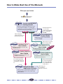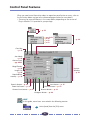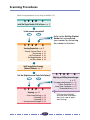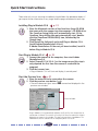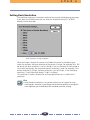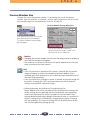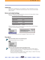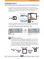
1
f o r
Macintosh
Plug-in Module CS-U 3.3
for CanoScan FB630U/FB636U Color Image Scanner
User's Guide
How to Make Best Use of the Manuals
When you open the box
Read
Safety Precautions
in the Product Guide first.
Printed Manual
CanoScan FB630U/FB636U
Getting Started
Describes operating procedure from set up
and software installation to scanning and
confirmation of operation. Please read before
using the scanner for the first time.
Windows
Detailed information
on care of the
scanner and handling
the accompanying
CD-ROM.
Macintosh
After reading this
guide and scanner is set
up and ready for use.
Electronic Manual CanoScan FB630U/FB636U
Product Guide
Detailed information on the scanner
and the CD-ROM.
Electronic Manual
Tells you how to get the
best scanning results.
ScanGear CS-U 5.3
User's Guide
Electronic Manual
Electronic Manual
Detailed information on how
to use Plug-In Module CS-U 3.3.
ScanGear Toolbox CS 2.1
Electronic Manual
User's Guide
ide
u
is G
Th
CanoScan Toolbox CS 1.2
User's Guide
Detailed information on how to use
ScanGear Toolbox CS 2.1.
Detailed information on how to use
CanoScan Toolbox CS 1.2.
After you have read this
book and mastered the
use of ScanGear CS-U 5.3
and ScanGear Toolbox CS
2.1...
Electronic Manuals
Plug-in Module CS-U 3.3
User's Guide
Detailed information on how to use
ScanGear CS-U 5.3.
After you have read this
book and mastered the
use of Plug-in Module
CS-U 3.3 and CanoScan
Toolbox CS 1.2.
Manual for Each
Application Software
Tells you how to use Ulead Photo Express 2.0
SE, Adobe PhotoDeluxe 2.0 and Omni Page
Limited Edition.
2
When using the
accompanying
application software.
How to Use this Guide
This guide explains how to use the Canon Plug-in Module CS-U 3.3 (herein referred to as
Plug-in Module CS-U) with application programs supporting CanoScan FB630U/FB636U, such
as Adobe PhotoDeluxe.
A plug-in is used within a compatible application program like Adobe PhotoDeluxe 2.0 to
expand its functionality and cannot be used as a stand-alone application. By only installing
the Plug-in Module CS-U from the CanoScan Setup Utility CD-ROM, Plug-in Module CS-U can
be simply plugged into the parent program and add the ability to scan.
Before using Plug-in Module CS-U, we strongly recommend reading this guide and keeping
this CD-ROM in a safe place for later reference.
Where to Look
Quick Start Instructions
p. 9
The Quick Start Instructions is a brief summary of commands and procedures that will
assist in using Plug-in Module CS-U immediately.
Installing Plug-in Module CS-U (Required Reading)
p. 12
All users should read this section to learn the procedures for installing Plug-in Module
CS-U software.
Scanning Preparations (Required Reading)
p. 18
All users should read this section to learn the procedures for adjusting magnification
and scan mode settings in preparation for scanning.
Scanning (Required Reading)
p. 33
All users should read this section to learn the procedures for scanning and saving images.
Adjusting and Editing Scanned Images
p. 39
Read this section for details about how to use Adobe PhotoDeluxe 2.0 to adjust
image brightness, color tone, and other attributes. You can read this section
according to your needs.
About the Conventions Used in this Guide
The following conventions are used in this guide to draw your attention to important
information.
CAUTION:
This symbol is used to highlight procedural precautions and limitations.
Always read these topics to avoid errors.
HINT:
This symbol is used to present helpful hints and supplemental information.
Reading these topics is recommended to enhance your enjoyment of
Plug-in Module CS-U.
3
Table of Contents
How to Use this Guide ........................................................................................... 3
Control Panel Features ........................................................................................... 6
Scanning Procedures .............................................................................................. 7
Plug-in Module CS-U Special Features .................................................................... 8
Quick Start Instructions .......................................................................................... 9
Installing Plug-in Module CS-U ................................................................ 12
Installing Plug-in Module CS-U ............................................................................. 13
Scanning Preparations ............................................................................. 18
Display Plug-in Module CS-U Control Panel .......................................................... 19
Previewing ........................................................................................................... 21
Set Preferences ..................................................................................................... 22
Set Magnification ................................................................................................. 26
Set Scan Mode ..................................................................................................... 28
Verify Image Before Scanning ............................................................................... 31
Scanning .................................................................................................... 33
Scan Area Settings ............................................................................................... 34
Zooming .............................................................................................................. 35
Scanning .............................................................................................................. 37
Saving Scanned Images ........................................................................................ 38
4
Adjusting and Editing Scanned Images .................................................. 39
Using the Histogram Feature to Adjust Image Contrast ......................................... 40
Adjusting the Image with Gamma Settings ........................................................... 42
Brightness and Contrast Settings .......................................................................... 44
Adjusting Gamma with the Menu ........................................................................ 46
Gamma Value Settings ......................................................................................... 48
Tone Curve Settings ............................................................................................. 50
Auto Tone Correction (ColorSync™) ..................................................................... 52
Descreen .............................................................................................................. 53
Brightness Settings for Black & White Images (Threshold Value) ............................ 54
Saving / Recalling Settings .................................................................................... 55
Editing Scanned Images ....................................................................................... 57
Scanning Techniques ............................................................................................ 58
Appendices ................................................................................................ 59
Troubleshooting ................................................................................................... 60
Error Messages ..................................................................................................... 62
Glossary ............................................................................................................... 63
Index .................................................................................................................... 65
Canon Customer Support Help Desk .................................................................... 67
5
Control Panel Features
When you need more information about an operation panel button or menu, refer to
the illustration below and go to the referenced page number for more details.
• There may be some differences in the screen below, depending on the version of
Plug-in Module CS-U provided in your package.
➜ p. 55
➜
➜
➜
➜
pp. 42-51
p. 40
p. 52
p. 53
➜ p. 22
Close Box
➜ p. 19
Scan Mode
➜ p. 28
Gamma Curve
➜ pp. 42-51
Magnification
➜ p. 26
Image Size
➜ p. 24
Required/Free
memory ➜ p. 30
Preview
Window
➜ p. 21
Scan Button ➜ p. 37
Zoom In Button ➜ p. 35
Zoom Out Button ➜ p. 36
Gamma Curve button ➜ p. 42
Preview Button ➜ p. 21
Browser Button ➜ p. 31
Histogram Button ➜ p. 40
HINT
In this guide, menu items are marked in the following manner:
Select [Load] from the [File] menu.
6
Scanning Procedures
Follow these procedures to use Plug-in Module CS-U.
S T E P
1
Install the Plug-in Module CS-U Software ➜ p. 12
Is the scanner connected?
S T E P
Refer to the Getting Started
Guide that accompanied
your scanner for connecting
the scanner instructions.
2
Scanning Preparations ➜ p. 18
• Display Control Panel
• Previewing
Set
Preferences
•
• Set Magnification
• Set Scan Mode
p. 19
p. 21
p. 22
p. 26
p. 28
Verify Image Before Scanning
(Browser Window) ➜ p. 31
Are the Brightness and Color Satisfactory?
S T E P
4
Adjusting and Editing Scanned Images
➜ p. 39
S T E P
• Histogram Adjustments
• Color Correction
• Auto Tone Correction
• Threshold Value
3
Scanning ➜ p. 33
• Scan Area Settings
• Zooming
• Scanning
• Saving Scanned Images
p. 34
p. 35
p. 37
p. 38
7
p. 40
p. 42
p. 52
p. 54
If the current brightness
and color pose no problem,
there is no need to adjust
these settings.
Plug-in Module CS-U Special Features
• See the Results of Adjustments Immediately (Dynamic Preview)
Once in preview mode, the results of adjustments to scan mode settings and colors are
promptly reflected in the preview image.
Highly detailed adjustments can be performed easily because you can see the results of
your changes as they are executed.
▼
▼
▼
• Supports ColorSync™ 2.0 or higher Auto Tone Correction
Supports ColorSync for the Macintosh operating system. Achieves superior color quality
by automatically compensating for and aligning the tones of various devices, such as
scanners, color displays and color printers.
▼
▼
▼
• Browser Function Permits Confirmation of the Real Image
Before Scanning
The Browser function lets you check the image to be scanned in detail before
commencing the scan. This function presents a much higher quality image than the
preview function.
▼
▼
▼
• Histogram Function Realizes Beautiful Contrast
Simple operation allows you to achieve beautiful contrast with half-tone gradations.
▼
▼
▼
• Gamma Curve Adjusts Image Brightness
The Gamma Curve feature provides four methods you can use to refine in detail the
level of image brightness until you are satisfied with the results.
▼
▼
▼
• Works within Image Processing Software for Easy Image
Editing
Plug-in Module CS-U can be used to extend the functions of plug-in compatible image
processing application programs.
8
Quick Start Instructions
Those who wish to start scanning immediately should follow the procedures below. If
you require further information at any stage, read the pages referenced at each step.
Installing Plug-in Module CS-U
11
Start Plug-in Module CS-U
22
p. 13
1. Place the Macintosh version of the CanoScan Setup CD-ROM
that came with the scanner into the computer’s CD-ROM drive.
The CanoScan Setup Utility will automatically start. (If the
CanoScan Setup Utility does not automatically start, doubleclick the [CanoScan FB630U/636U] icon, followed by the
[Setup] icon.)
2. Click [Install the Software] and install Plug-in Module CS-U.
(Install Adobe PhotoDeluxe 2.0 first.)
If Adobe PhotoDeluxe 2.0 has not yet been installed, install it
before Plug-in Module CS-U.
p. 19
1. Connect the scanner to the computer, then start Adobe
PhotoDeluxe 2.0.
2. Select [CanonPI CS-U 3.3.0...] as the image source (this step is
only required the first time the scanner is used with the
program)
3. Click the scanner icon.
• Plug-in Module CS-U will start and display its control panel.
Start the Preview Scan
33
p. 21
1. Place the materials to be scanned on the scanner.
2. Click the preview scan button (
).
• The entire document glass area will be scanned and displayed in the
preview scan window.
Preview Window
➟
Plug-in Module CS-U automatically calibrates itself the first time the preview or
scan button is clicked. The scanner will run by itself for a few moments without
displaying an image in the window. This does not constitute a breakdown. The
calibration results are stored until the computer power is shut off.
9
Set the preferences, magnification and scan mode settings.
pp. 22-30
4
4
• The preference settings provide settings for how the system operates.
(p. 22)
• The magnification setting determines how you want the image
enlarged or reduced. (p. 26)
• The scan mode setting determines the kind of image you want to scan:
black and white, gray, or color. (p. 28)
Verify Image Quality with the Browser Function Before Scanning
55
p. 31
1. Click on the [Browser] button.
• The Selection Frame will appear.
➟
2. Move the Selection Frame to specify the area of the image you
want verified and click the mouse button.
• Plug-in Module CS-U will read the image and display the browser image.
3. After you have examined the browser image, click the mouse
anywhere.
Specify the Area of the Image to be Scanned
6
p. 34
1. Select the area to be scanned by clicking and dragging the
mouse pointer over the image.
• You may find it convenient to use the zoom feature to select small areas
or to select specific scan areas with precision. (p. 35)
10
Scan the Image
77
p. 37
1. Click on the [Scan] button.
➟
• Plug-in Module CS-U will scan the image.
• When the scan is complete, the Plug-in Module CS-U control panel will
close. In PhotoDeluxe 2.0, the image will appear in the Edit window.
Save the Scanned Image
8
p. 38
1. Save the image with the application software, specifying a
folder, file name and file format.
11
S T E P
1
Installing Plug-in Module CS-U
Step 1 describes how to install Plug-in Module CS-U.
If it has already been installed according to the instructions in the Getting Started Guide,
there is no need to perform the procedures described in Step 1.
Installing Plug-in Module CS-U
12
p. 13
S T E P
1
Installing Plug-in Module CS-U
If Plug-in Module CS-U has already been installed according to the instructions in the
Getting Started Guide that came with the scanner, there is no need to perform the
following procedures. Proceed to Step 2, Scanning Preparations.
Caution
Before you can install Plug-in Module CS-U, you must have installed
PhotoDeluxe 2.0 or Photoshop (Ver. 3.0 or higher) on your hard disk.
Install this program before attempting to install Plug-in Module CS-U.
Operating Environment
Hardware
Power Macintosh G3 or iMac computers equipped with USB ports
(Performance with Macintosh compatibles is not guaranteed)
Main Memory
32 MB or more recommended
Application Software
PhotoDeluxe 2.0
Adobe Photoshop (Ver. 3.0 or higher)
Display
16-tone grayscale-capable monitor (32,000-color-capable monitor
recommended). Black and white and 4-tone monochrome monitors
cannot be used.
System Software
System 8.5.1 or later (iMac computers running Macintosh System
Software 8.5.1 require the iMac Update 1.1)
iMac Update 1.1 can be obtained from CD-ROMs included with
Macintosh-related magazines and the iMac support page of the Apple
Computer, Inc., web site.
13
S T E P
1
Procedures
Follow the procedures below to install Plug-in Module CS-U by itself.
Caution
If Plug-in Module CS-U has already been installed according to the instructions
in the Getting Started Guide, there is no need to perform the following
procedures.
Place the Macintosh version of the CanoScan Setup CD-ROM that came
with the scanner into the computer’s CD-ROM drive.
Language select window will display to select your language, then the CanoScan Setup
Utility menu window will display.
• If the CanoScan Setup Utility does not automatically start, double-click the
[CanoScan FB630U/636U] icon, followed by the [Setup] icon.
Click the [Install the Software] button.
The following window will display.
➟
If you click the [No] button, the Install window will display.
Click the check boxes of the programs other than Plug-in Module CS-U to
remove the check marks.
14
S T E P
Click the [Start Installation] button at the window’s bottom right.
➟
Read the instructions carefully and click the [Next] button.
If this message displays,
do not click [Restart].
Click the [Continue]
button.
Click the [Next] button to proceed.
➟
Click the [Yes] button to start the installation.
➟
15
1
S T E P
1
Confirm the folder for the installation and click the [Install] button.
➟
• If additional application programs will be used with Plug-in Module CS-U other
than Adobe PhotoDeluxe 2.0, click the [Add Install Location...] button and add
those applications.
When the “installation was successful” message displays, click the [Quit]
button.
➟
Click the [Exit] button of the CanoScan Setup Utility.
Restart the computer as prompted by the on-screen messages.
• After the computer has restarted, remove the CanoScan Setup Utility
CD-ROM (Macintosh) from the CD-ROM drive.
➟
16
S T E P
1
Caution
• The ColorSyncTM Profiles file is installed along with Plug-in Module CS-U.
ColorSyncTM Ver. 2.0 or higher is required to use these profiles with the
automatic color matching system (p. 52).
• The following display profile files are available: CANON gamma 1.5 monitor,
CANON gamma 1.8 monitor, CANON gamma 2.1 monitor. If you wish to adjust
the color balance of the display, double-click [ColorSync TM System Profile] in
the Control Panel folder and select from the following system profiles.
• CANON gamma 1.5 monitor
• CANON gamma 1.8 monitor
• CANON gamma 2.1 monitor
• Please reinstall Plug-in Module CS-U after you have emptied the Trash.
17
S T E P
2
Scanning Preparations
Step 2 presents the essential preparations for scanning. The following
procedures are explained on the indicated pages.
Display Plug-in Module CS-U Control Panel
p. 19
Setting the document on tne scanner
and pre-scan
p. 21
Previewing
p. 21
Set Preferences
p. 22
Set Magnification
p. 26
Set Scan Mode
p. 28
Verify Image Before Scanning
p. 31
18
S T E P
2
Display Plug-in Module CS-U Control Panel
All scanning operations are performed with the Plug-in Module CS-U control panel.
To quit Plug-in Module CS-U, click on the close box at the top left of the control panel.
Perform the settings for the scan mode, image quality, magnification, etc.
Close Box
Quit Plug-in Module CS-U.
Menu Bar
Click on any menu item to display more
options in a pull-down menu.
Buttons
Use these buttons to change the zoom
setting and scan images.
Preview Window
Displays the image in preview mode.
The image display size and disk size that
were specified in the Preview window are
automatically displayed here.
19
S T E P
2
Operating Procedures
Verify that the scanner is attached to your computer and that its power
switch has been activated.
Read the Quick Start Instructions for instructions on how to connect the scanner.
See Quick Start Instructions (p. 9).
Start PhotoDeluxe 2.0 or Photoshop.
Select Plug-in Module CS-U from within PhotoDeluxe 2.0 or Photoshop.
➟
<Adobe Photoshop>
1. Choose the [File] menu, [Import] and
[Plug-in Module CS-U].
Import
➟
<Adobe PhotoDeluxe 2.0>
1. Click the [Get Photo] button and the
[Get Photo] tab.
)
2. Click the [Scanners] button (
and select [CanonPI CS-U 3.3.0...]
from the Select Input Source dialog
the first time you use the program.
From the second time on, click the
).
[Scanner] icon (
The version of Plug-in Module CS-U
shipped with your package may differ
from that pictured above.
The Plug-in Module CS-U control panel will appear.
Caution
Plug-in Module CS-U cannot be operated as a stand-alone program. Always
start it from within an application program, such as Adobe PhotoDeluxe 2.0
or Adobe Photoshop.
20
S T E P
2
Previewing
You can pre-scan the original before it is actually scanned and acquired by the parent
application. Because the pre-scanned image is temporary, the entire platen is scanned.
The pre-scanned image is displayed in the preview window where the quality of the
image can be adjusted or cropped for actual scanning.
Operating Procedures
Set the original on the scanner document glass.
• Open the scanner document glass cover, set face down the side of the page you
want to scan with the top edge of the page toward you, and align with the
marks as shown in the illustration.
• Set the original on the document glass and close the cover carefully so it does not
shift out of position.
Bottom
Top
Click on the [Preview] button.
• The image will be read and the image will appear in the Preview window.
➟
Hint
• For details about the types of originals you can set on the scanner document
glass for scanning, refer to the Getting Started Guide.
• The Preview window can be adjusted to a larger size (p. 23).
• The Dynamic Preview function enables changes to settings, such as the scan
mode and brightness, to be immediately reflected in the preview image.
• Nevertheless, the preview image provides only an approximation of the scan
and the final results may differ to some degree from the preview image.
21
S T E P
2
Set Preferences
You can set preferences for the operating environment which will be used for every
scanning job until you change them. Some of these settings include units of measure
for the display, basic resolution, size of the preview window.
You can also return all the settings to their default values. These settings are
performed in Preferences menu of the operation panel.
Unit
Specifies the units that define the size of the scanned image.
Unit Dialog Box
The units displayed in this section of the control panel will change.
Click on the [Prefs] menu in the control panel and select [Unit].The Unit Settings dialog
box will appear.
Unit Settings Dialog Box
Select the desired settings.
22
S T E P
2
Setting Basic Resolution
The resolution setting sets the output resolution for printing and displaying the image.
If you select the [Other] button you can enter the resolution setting (12 to 9600)
directly into the entry box.
basic Resolution Setting Dialog Box
When the image is output to a printer, to a Bubble Jet printer in the color or gray
mode, for example, the basic resolution of the printer is halved. For example, for a 360
dpi printer the basic resolution is set for 180 dpi. If you use the black & white mode or
use a color laser printer, the same resolution of the printer is used. For example, if the
printer resolution is 300 dpi, the basic resolution is set to 300 dpi. As for the display
resolution, 72 dpi (Macintosh display 72 dpi) is sufficient.
This resolution is used as the basic for setting magnification so it is called “basic”
resolution.
Hint
• Once the basic resolution is set, you do not have to set it again for every
scanning job. However, if you change the destination printer, or change the
scanning mode, you should adjust the standard resolution setting.
23
S T E P
2
Preview Window Size
Changes the size of the preview window. If you enlarge the size of the preview
window, then the resolution is increased. You can specify whether or not to save the
pre-scanned image with the preferences file or the settings file.
Preview Window Settings Dialog Box
Click on the [Prefs] menu in the control
panel and select [Preview Window].
The Preview Window Settings dialog
box will appear.
Click on the check box to determine
whether the preview image is saved in the
preference file or the settings file.
Caution
• Changing the Preview window size will cause the image previously displayed
in the Preview window to disappear.
• The maximum size of the area that you can specify depends on the size and
other characteristics of your monitor.
Hint
• If the “Save preview in preference file” option is selected, the last preview
image will appear in the Preview window when Plug-in Module CS-U is
launched again after quitting once. This reduces the steps required to rescan
the same image repeatedly.
• If the “Save preview in setting file” option is selected, the preview image will
be saved in a settings file. This is convenient when you wish to keep the
settings associated with a particular image.
• Difference Between the Preferences File and Settings Files.
Plug-in Module CS-U creates two kinds of files to keep track of settings. The
various settings that are adjusted with the control panel are automatically
saved in the preference file, which is located in the System folder. These
settings determine how Plug-in Module CS-U behaves when it is restarted. In
contrast, settings files are intended for saving particular groups of settings
that are used often. The names of settings files can be freely chosen by the
user. See Saving/Recalling Settings (p. 53).
24
S T E P
2
Calibration
If the scanner’s color balance is out of equilibrium, select [Calibration] to start the
adjustment process. Calibration automatically adjusts the scanner to read standard
white as white.
Return to Default Settings
Returns the preference settings and all other settings to the factory default settings.
The tables list the major default settings.
Scan Mode
Gamma setting
Magnification
Unit
Basic resolution
Preview Window size
Control Panel Position
24-bit Color
Menu setting (CRT type for B)
100%
Pixels
72 dpi
20 dpi
Center
Click on the [Prefs] menu in the control panel and select [Resets Default Settings].
The Default Settings dialog box will appear.
Click on the [Yes] button if you wish to proceed. Otherwise click on [No].
Procedures
Select the [Prefs] menu in the control panel.
The Settings pull-down menu will display.
Select the desired option from the pull-down menu.
• Selecting any one of the Units, Basic Resolution or Preview Window options
displays the respective dialog for it. Choose the desired value in the dialog and
select [OK] to change the setting.
• A confirmation dialog will display if Resets default settings is selected. The settings
will be reset if [Yes] is selected in that dialog.
25
S T E P
2
Set Magnification
The magnification of an image can be changed before scanning to accommodate
reproductions that are larger or smaller than the original. The settings can be changed in
increments of 1%. While the size of an image can be changed through other means,
enlarging an image during the scanning process can save time by eliminating
unnecessary steps.
Scanning with horizontal/
vertical 2x magnification
Scanning with horizontal/
vertical 0.5x magnification
Changing the magnification setting causes the resolution display on the control panel to
change correspondingly. This resolution setting is referred to as the “scanning resolution.”
Output Device Resolution= 360 dpi, Magnification= 100%
➟
Magnification
changed to
50%
Magnification
Scanning Resolution
➟
The scanning resolution changes
accordingly.
Hint
Magnification and Resolution
Why does the image size change with the magnification? Let us answer this
with an example using an “BJ (360 dpi)” output device. If you were to scan an
image with this device setting and set the magnification factor to 50%, the
scanning resolution will automatically change to 180 dpi. At this setting, the
image will be scanned at a resolution of 180 dpi and the output device will
convert this to 360 dpi, shrinking the size of the output in the process because it
will only have half the data with which to fill the space.
26
S T E P
2
To Set the Magnification Factor
Set the desired magnification factor on the control panel.
Slider
Drag the slider bar in
either direction or use
the arrow keys to
change the resolution.
Click here to return the
magnification factor to 100%.
Click inside these boxes to enter
values directly.
Hint
The Relationship Between Data Volume and Scanning Resolution
The higher the magnification and scanning resolution settings, the greater the
file size of scanned images. There are certain inconveniences associated with
overly large data volume, such as the inability to fit a file on a single floppy disk
and the risk of causing a temporary computer slowdown by
overwhelming its processing capabilities. For example,
21MB
if you scan a standard size photograph in the color mode,
the amount of data varies according the resolution.
5.2MB
9 X 13cm image
2.3MB
580KB
100dpi
200dpi
300dpi
600dpi
* These numbers are approximate estimates and may differ from actual scan results.
27
S T E P
2
Set Scan Mode
When an image is scanned, it is read as a collection of “dots.” The scan mode that is
selected determines how each of these dots is represented in the output. The following
five scan modes are available.
Black and White Mode (Line)
Displays each dot as either black or white. Grays and halftones are also reproduced
as black or white. The Black and White mode is best for documents that contain
text and line drawings and not suited for images with color gradations.
Black and White Mode (Diffusion Dither)
Displays each dot as either black or white. In order to create gray tones this method
uses randomly dispersed black dots on white to create a more natural looking
gradation.
Grayscale Mode (8-bit)
In the Grayscale mode, each dot is formed by assigning it eight individual “bits” of
data. By combining these bits in various different ways, a dot can be expressed in over
256 distinct shades. Photographic images are reproduced relatively naturally in this
mode, but the file size is much larger than that produced by the Black & White mode.
28
S T E P
2
Color Mode (24-bit)
In the Color mode, each dot is formed by assigning it eight individual bits of data to
represent each of the RGB or red, green and blue colors, which add up to 24 bits. In
this mode, a dot can be expressed in approximately 16,770,000 distinct shades. This
mode is useful for reproducing color prints, but generates files that are even larger
than the Grayscale mode.
High Definition Color
Select for the best possible color quality. Scanning at this setting will be slightly
slower than color mode.
29
S T E P
2
Hint
Scanning the same image in the three different scan modes produces different
file sizes. By size, Black & White mode requires the least disk space, followed in
order by the Grayscale mode and the Color mode. Before scanning, check the
data volume indicator on the control panel.
The numerator indicates the amount of disk
space required for the scanned image while
the denominator indicates the amount of
disk space available. When the required
space exceeds the available space, the scan
button is unavailable.
To Set the Scan Mode
Select the Scan Mode box on the control panel and choose the desired scan
mode.
Scan Mode is displayed in the pull-down menu.
Selecting the box opens the
pull-down menu.
Select the scan mode that you want.
30
S T E P
2
Verify Image Before Scanning
Before initiating the final scan, it is advisable to check the intended results with the
Browser function. The image in the Browser window is more accurate than the one in
the Preview window, allowing you to verify the results more precisely before scanning.
To Verify the Image
Set the magnification and scan mode to the appropriate settings (pp. 26-30).
Click on the [Browser] button.
• The Selection Frame will appear on the Preview window to enable a portion of the
image to be selected.
• The size and shape of the Selection Frame cannot be changed because it is
automatically determined by the scanning resolution setting.
➟
Hint
The Browser button is disabled when the image area is unspecified or is too
small (less than approximately 64 x 64 pixels).
Move the pointer in the selection frame inside the preview window.
• The mouse cursor will change to a “+” sign shape.
Move the Selection Frame to the desired position with the mouse cursor.
• Moving the mouse will move the Selection Frame.
31
S T E P
2
Click the mouse button when the Selection Frame is in the correct position.
• The image will be read and the browser image displayed in the middle of the
monitor.
Once you have examined the browser image, click the mouse button again
to close the Browser window.
• The Browser window will close.
• It does not matter where the mouse cursor is positioned to close the Browser window.
32
S T E P
3
Scanning
Step 3 presents the procedures for conducting the final scan,
saving the scanned image in a file and editing image files.
Follow these procedures to perform scanning jobs.
Scan Area Settings
p. 34
Zooming
p. 35
Scanning
p. 37
Saving Scanned Images
p. 38
33
S T E P
3
Scan Area Settings
Using the image in the preview window, you can define the actual area to be scanned.
Operating Procedures
Position the pointer in the preview window.
The + symbol marks the current position of the pointer.
Click the mouse button and drag the mouse in the direction you want to
define on the image as a frame.
The selected area is enclosed in a dotted frame. The area enclosed in this dotted frame
is the area that will actually be scanned.
Selection
Frame
• Clicking the mouse button outside the Selection Frame causes the selected area to
be deselected.
• Change the position of the Selection Frame by moving the pointer inside it, as it
changes into an omni-directional arrow [ ]. Clicking and dragging the cursor in
this state will cause the Selection Frame to move without changing its shape.
• Placing the mouse cursor over the dotted line of the Selection Frame causes the
cursor to change into one of four shapes [ ] [ ] [ ] [ ]. Dragging the
Selection Frame with the mouse cursor changes the shape of the Selection Frame.
• Double-clicking the mouse button anywhere in the Preview window selects the
entire image.
Hint
• To specify small areas with precision, it is convenient to expand the preview
display with the Zoom In button. See Zooming on the (P. 35).
34
S T E P
3
Zooming
You can specify a selected area of the image for enlargement with the Zoom
features. You can use the zoom function to select an area with high precision,
or to select small areas for scanning.
To Zoom In
Select the area you want to enlarge with the zoom function.
See operating procedures (p. 34).
Selection Frame
➟
Hint
• The Zoom In button can’t be activated unless an area has been selected in the
Preview window.
• You can zoom an area of the screen continuously in up to seven steps. The
] cannot be clicked if the slected area is too small.
Zoom in button [
35
S T E P
Click on the Zoom In button [
3
].
The selected area will be displayed in expanded form.
If you want to enlarge the image again, reduce the size of the area selected with the
frame and click the Zoom In button again.
➟
To return to normal view, click the Zoom Out button [
36
].
S T E P
3
Scanning
Once you have set the magnification and scan mode, you may proceed with the scan.
Once the scan is complete, Plug-in Module CS-U automatically closes and returns to the
application software, such as PhotoDeluxe 2.0. The following provides an example of
scanning from within PhotoDeluxe 2.0.
To Initiate the Scan
Specify the Scan Area.
See operating procedures (p. 34).
Click on the [Scan] button.
➟
• The image will begin to be scanned.
• When complete, the Plug-in Module CS-U control panel will close and the Save file
dialog box will display. To save an image file, see Saving Scanned Images (p. 37).
Hint
• The scan button [
] cannot be clicked if the scan area is set too small (less
than 64 x 64 pixels) or not specified.
• The scan cannot be performed if the required memory is larger than the free
memory.
37
S T E P
3
Saving Scanned Images
After an image has been scanned, the data should be saved in a file to a disk using
PhotoDeluxe 2.0. For a more detailed treatment of these procedures, see the
PhotoDeluxe 2.0 User’s Guide.
To Save an Image
After the scan is complete, the scanned image will display in the Save
dialog of Adobe PhotoDeluxe 2.0. Use the following procedures to specify
the save location, file name and image type to save the scanned image.
Specify the folder and file name that you wish to use for the image in the
Save this document as: dialog box.
Click the [Save] button.
• The final scan will start. When the scan is completed, the image will be saved and
its thumbnail will display in the [My Photos] window.
38
S T E P
4
Adjusting and Editing
Scanned Images
Scanned images may be corrected for brightness and color tone or edited in a variety of ways.
The potential adjustments vary with the type of scan mode utilized in the original scan.
Adjustments to the scanned image may be made after the image is previewed.
Color Mode
Using the Histogram Feature to Adjust Image Contrast
Color Correction: Gamma Settings
Color Correction: Brightness and Contrast Settings
Color Correction: Adjusting Gamma with the Menu
Color Correction: Gamma Value Settings
Color Correction: Tone Curve Settings
Auto Tone Correction (ColorSync™)
p.
p.
p.
p.
p.
p.
p.
40
42
44
46
48
50
52
p.
p.
p.
p.
p.
p.
40
42
44
46
48
50
p.
p.
p.
p.
p.
42
44
46
48
50
Grayscale Mode
Using the Histogram Feature to Adjust Image Contrast
Color Correction: Gamma Settings
Color Correction: Brightness and Contrast Settings
Color Correction: Ajusting Gamma with the Menu
Color Correction: Gamma Value Settings
Color Correction: Tone Curve Settings
Diffusion Dither
Color Correction: Gamma Settings
Color Correction: Brightness and Contrast Settings
Color Correction: Ajusting Gamma with the Menu
Color Correction: Gamma Value Settings
Color Correction: Tone Curve Settings
Black & White Mode
Brightness Settings for Black & White Images (Threshold Value)
Descreen
Saving/Recalling Settings
Editing Scanned Images
Scanning Techniques
39
p. 54
p.
p.
p.
p.
53
55
57
58
S T E P
4
Using the Histogram Feature to Adjust Image Contrast
The data comprising an image contains a variety of brightness settings ranging from
shadows to highlights. These settings are represented in Plug-in Module CS-U by values
ranging between 0 and 255. The difference in these values determines the image’s
contrast. To show how much of the image data falls into each brightness setting, Plugin Module CS-U contains a Histogram feature that shows this data distribution clearly.
With the Histogram you can adjust the level of shadows and highlights to achieve
beautiful tones with the best possible contrast.
Hint
• You may not alter the histogram for images scanned in the Color mode when
ColorSync is active or for images scanned in the Black & White mode.
• You can use the Histogram only with grayscale, color or high definition color
images.
How to Interpret Histograms
You can select the entire image or specify an area for which a histogram will be
generated. The height of the peaks of the histogram is directly related to the volume
of data with the corresponding value.
Portion with
Highlights
Distribution of data
with a bias toward
highlights.
Portion with
Shadows
Distribution of data
with a bias toward
shadows.
Entire Image
Distribution of data
widely distributed
between shadows and
highlights.
How to Adjust Histograms
To change the contrast in an image, the distribution of data between shadows and
highlights can be adjusted by dragging the shadow and highlight marks at the bottom
of the histogram. All of the data lying to the outside (left) of the shadow mark is
changed to a zero value and all of the data lying to the outside (right) of the highlight
mark is changed to a 255 value. The examples below show adjustments to improve the
contrast. Use the Auto setting to adjust the Histogram for most jobs (p. 41). The
graphs below show images adjusted with the Auto setting.
IMAGE Image with a bias
1
toward highlights
Move the shadow mark
toward the highlight end.
IMAGE Image with a bias
2
toward shadow
Move the highlight mark
toward the shadow end.
40
IMAGE
3
Image with well
distributed data
Move both the shadow and
highlight marks inward.
S T E P
4
To Adjust a Histogram
Specify the area of the image (the entire area to be scanned) for which a
histogram will be generated. See Scan Area Settings (p. 34).
The histogram will not display correctly if an extremely small area is selected. To select
small areas, first expand the display with the Zoom In button. See Zooming (p. 35).
Click on the [Histogram] button.
The Histogram dialog box will display.
Click the Auto button.
Although you can freely move the shadow mark and highlight mark to another
position, the image can be adjusted easily for optimum effect with the Auto button.
Clicking directly on this bar causes the shadow or highlight mark,
whichever is closest, to advance to that position.
Shadow Mark
All of the data to the left of
this mark is set to the
shadow (0) value. Drag the
mark to the right or left.
Highlight Mark
All of the data to the
right of this mark is set
to the highlight (255)
value. Drag the mark
to the right or left.
These boxes, respectively,
display the brightness
values corresponding to the
position of the shadow and
highlight marks. These
values can be specified by
typing directly in the boxes
or by clicking on the arrows.
The histogram settings
can be saved in a file
and reloaded for later
use.
Click on the [OK] button.
The preview image will change according to the values specified with the histogram.
Hint
The Histogram dialog box can also be displayed by selecting [Histogram] from
the [Image] menu.
41
S T E P
4
Adjusting the Image with Gamma Settings
An image scanned with Plug-in Module CS-U is a composite of individual square dots.
Each dot contains information that defines its level of brightness. Plug-in Module CS-U
can manipulate this data and reproduce adjusted images on the screen. This type of
data conversion is referred to a gamma adjustment.
The data created when the scanner scans an original is called input; the image
displayed on the screen is called output. When this input and output data are plotted
on the same curve, this is called a gamma curve. By changing the gamma curve, you
can adjust the brightness of an image.
Plug-in Module
DISPLAY
SCANNER
HIGHLIGHT
Gamma curve
OUTPUT
BRIGHTNESS
A straight or curved line indicates
the gamma status.
SHADOW
SHADOW
HIGHLIGHT
INPUT BRIGHTNESS
Setting the Gamma
You can use one of four methods available in the Color Correction dialog box to set the
gamma curve. A description of each method is provided on the following pages.
Using the slider bar — Adjusts the
brightness and contrast of the original
image. (p. 44)
Setting the gamma value — When you
cannot do the optimum setting with the
menu. (p. 48)
Using the menu — Set to match the
display type. (p. 46)
Setting the graph — Fine adjustment of
the gamma graph. (p. 50)
The settings you perform in the Color Correction
dialog box can be saved to a file and opened
again whenever you need them.
42
S T E P
4
The Relationship Between the Gamma Curve and Image Brightness
Gamma curve values fall with a range of 0.01 to 10.00. A gamma value of 1 appears
as a straight line in the gamma graph, and if the value is any value other than one, the
line on the gamma graph will appear curved. The relationship between the shape of
the gamma curve and image brightness is explained below.
Input and output and are equal
and the gamma curve appears as
a straight line, and the input
image is displayed on the screen
without adjustment.
Output
Gamma = 1
➟
Gamma < 1
The data bends upward from the
input shadow to highlight into
the output area bending the curve
up and making the adjusted
image brighter in the display.
Output
Input
➟
Gamma > 1
The data bends downward from
the input shadow to highlight
away from the output area
bending the curve down and
making the adjusted image darker
in the display.
Output
Input
➟
Input
CAUTION
• The gamma curve cannot be adjusted for a high definition color image that
has been set with ColorSync because the tone adjustment is performed
automatically.
• The gamma curve cannot be adjusted for a Black & White (Line) image
because mid-tones are shown as either black or white. To adjust the
brightness of a Black & White image, use the threshold setting. (p. 54)
43
S T E P
4
Brightness and Contrast Settings
You can adjust the gamma curve with two slide bars, one for contrast and one for
brightness. Use this method to adjust an image before scanning if it is slightly out of
focus or too dark.
Hint
You cannot use this feature with a Black & White (Line), color or high definition
color file that has been set with ColorSync™.
Contrast
Contrast is the difference between the lightest light and the darkest dark in the
image. A high contrast setting creates a great difference between light and dark
shades, and there is a very sharp distinction between light and dark areas of the
image. A low contrast setting creates a small differnce between light and dark
shades and the distinction between light and dark areas of the image are not so
obvious.
Contrast = 128 (Normal)
Contrast = 170
Contrast = 100
If the image appears slightly out of focus, increase the contrast settting for a
sharper image. However, if the contrast setting is too high, shadows will blacken
and the highlights will wash out.
Brightness
Brightness is the overall lightness or darkness of an image without changing the
contrast. Adjust the brightness setting to change the overall lightness or darkness
of the entire image. However, if the brightness setting is too high, the highlights
will wash out, and if too low the shadows will blacken.
Brightness = 190
Brightness = 128 (Normal)
44
Brightness = 80
S T E P
4
To Adjust the Brightness and Contrast
[
] Click the gamma button.
The Color Correction dialog opens.
Click the check box for Slider Setting then use the slider bar to set the
brightness and contrast.
Slider
[
] Drag the button to the left or the right or click the
left or right arrow [
][
] to change the setting.
Check Box
Resets value to 128
Shows the changes in the values as you move
the slider
Click the OK button.
The image in the preview windows immediately reflects the changes.
Hint
• You can also open this dialog box by pulling down the Image menu in the
operation panel and selecting Color Correction.
• If you select Slider Setting in this dialog box, you can also use the operation
panel slider to make the settings.
45
S T E P
4
Adjusting Gamma with the Menu
[
] You can select the display type with the menu and set the gamma curve. Use this
feature when you see the brightness of the original image does not match the
brightness of the image in the preview window or browser. In the menu if you can
select CRT Type A, CRT Type B, or CRT Type C, or Linear, the optimum gamma settings
will be performed for you automatically.
Hint
• You cannot use this feature with a Black & White (Line), color or high
definition color file that has been set with ColorSync™.
• The gamma settings of display are intended to produce effects that emulate
the reproduction of color tones that appear natural to the human eye. In
order to achieve this and be able to accurately reproduce the tones of the
original on the display, the display scanner gamma value must match the
gamma value of the display.
CRT Type A
Select if the CRT Type B setting displays an image that is too bright.
CRT Type B
Use for a Macintosh display.
CRT Type C
Select if the CRT Type B setting displays an image that is too dark.
Linear
Select to restore the gamma setting to 1.
Hint
• If all the settings above produce an image of brightness that does not
compare favorably with the original, calculate the reciprocal value of the
display gamma value and enter the reciprocal value directly to perform the
setting. (p. 48)
46
S T E P
4
To Change the Gamma Value Settings
[
] Click the gamma button.
The Color Correction dialog box opens.
Click the radio button for Menu Setting.
Radio button
➟
Click this button to pull
down the menu.
Click the OK button.
The image in the preview window changes to reflect the change in this setting.
Hint
• You can also open this dialog box by pulling down the Image menu in the
operation panel and selecting Color Correction.
47
S T E P
4
Gamma Value Settings
[
] You can also set up the gamma curve by directly entering the gamma value (0.0110.00). Use this method when you cannot adjust the gamma value with the menu (p. 46).
Hint
• You cannot use this feature with a Black & White (Line), color or high
definition color file that has been set with ColorSync.
Adjusting the Gamma Value to Match the Display
Normally the gamma setting does not have to be adjusted because Plug-in Module CSU has been pre-set with the menu setting to match a true Macintosh display (CRT Type
B). However, if you are using another display and after you adjust the gamma value
with the CRT Type A or CRT Type C setting, and the images are still too light or too
dark, then use the calculation method below to calculate and set the reciprocal value of
the display value.
1
=
Display gamma value
Plug-in
Module CS-U
gamma value
1
For a display
gamma value
of 1.8 ...
= 0.56
1.8
Sending Output to a Printer
The gamma value does not have to be adjusted for output to a color printer because
the printer driver settings are set to match the display, and matching the gamma
setting of the display does not present a problem. Similarly, the gamma setting does
not have to be done for a monochrome printer.
For fine adjustment, view the image on the display to view the results of your output.
Hint
• If you do not know the gamma setting of your display, refer to the manual
provided with purchase of the display. If you do not find the gamma value in
the manual, or if the manual is not available, contact the manufacturer of
your display.
48
S T E P
4
To Change the Gamma Value Settings
[
] Click the Gamma button.
The Color Correction dialog box opens.
Click the radio button for Gamma Value Setting and set the gamma value.
Resets the value to 1.00
Reflects the value of the setting
selected with the slider bar.
Without using the slide bar, you
can also enter the value directly
by clicking the value to change it.
Slider
[
] Drag the button to the left or
the right or click the left or right
arrow [
][
] to change the
setting.
Click the OK button.
The image in the preview window changes to reflect the change in this setting.
Hint
• You can also open this dialog box by pulling down the Image menu in the
operation panel and selecting Color Correction.
49
S T E P
4
Tone Curve Settings
You can edit the gamma curve directly by changing the shape of the line on the graph.
When you change the gamma setting by manipulating the curve, you can perform fine
adjustments in the brightness of only the shadows, only the highlights, or both the
shadows and highlights.
Hint
• You cannot use this feature with a Black & White (Line), color or high
definition color file that has been set with ColorSync.
Manipulating the Graph
The following example show you how to manipulate the graph to change the
gamma settings. This is only an example. When you test these settings yourself,
you can see the changes in the gamma settings immediately reflected in the preview
window or the browser to achieve many interesting effects.
Drag the mid-tones of the input side
(scanned image) into the highlights of the
output side (displayed image)
Unadjusted
Gamma Curve
If you want to
increase the
light areas ...
Reverse the starting and end points of the
line to reverse shadows and highlights.
If you want
reverse the
shadows and
highlights ...
(If the image is in color, the colors are
switched to their complementary colors.)
50
S T E P
4
To Edit the Tone Curve
[
] Click the gamma button.
The Color Correction dialog box opens.
Click the radio button for Tone Curve and adjust the gamma setting.
Radio button
You can adjust the setting for each channel: R (red), G
(green), B (blue) or M (RGB or grayscale). You can adjust
each channels independently. (You can adjust RGB only for
a high definition color image.)
Resets the gamma curve to
a straight line.
Shows the input and output
level at the point under the
pointer (control point) in
the graph, expressed as a
value from 1 to 255 where
1 is the darkest and 255 the
lightest. [ I ] is for input and
[O] is for output. If the
output level is larger than
the input level, this results
in a lighter image.
To create a control point on the line, just click any location on the line. After a control point is
displayed in the line you can drag it in any direction. As you drag it to another location, the
gamma value changes. You can set several control points on the gamma curve.
Click the OK button.
The image in the preview window changes to reflect the new settings.
Hint
You can also open this dialog box by pulling down the Image menu in the
operation panel and selecting Color Correction.
51
S T E P
4
Auto Tone Correction (ColorSync™)
When the scan mode is set to color and high definition Color, color correction is
automatically conducted by the ColorSync™ function. The ColorSync™ function
automatically matches the tones produced and displayed by scanners, displays and color
printers. Optimal color correction is achieved with ease without having to make
adjustments with the histogram or other color correction functions.
Caution
More time is required to start the program and scan when the ColorSync™
function is activated.
Hint
• ColorSync™ responds differently to each computer according to the unique
conditions affecting it (type of display used, etc.), which may cause differences
even between computers of the same make and system version. The tone
characteristics of an image scanned with ColorSync™ on one computer,
therefore, may change when processed on another computer.
• Color correction using the histogram function and gamma value settings can’t
be conducted when the ColorSync™ function is activated.
To Activate the ColorSync™ Function
Click on the [Image] menu and the [ColorSync] option in the control panel.
Color correction will occur automatically. Auto tone correction requires some time to
process.
52
S T E P
4
Descreen
Moiré patterns occasionally appear when items printed at low resolutions are scanned.
Moiré patterns are dot-like patterns that interfere with processing images for
professional use and are usually caused by poor dithering resulting from scanning
images from newspapers, books, magazines, etc. To reduce this phenomenon, scan
photographs and other low-resolution prints with the descreen activated. Shut it off to
scan higher resolution items. The default setting is “off”.
Caution
• The Descreen cannot be switched on for scanning resolutions higher than 601
dpi.
• The previous setting is enabled for the Descreen when Plug-in Module CS-U is
opened by a software application operating in the windowless mode.
Procedure
Open the [Image] menu and select [Descreen].
53
S T E P
4
Brightness Settings for Black & White Images (Threshold Value)
When the scan mode is set to Black & White (Line), the image brightness can be
adjusted. The threshold value setting determines whether a half tone will be expressed as
a black or a white data point. The possible threshold values range between 1 and 255.
Below a given threshold value, all data is converted to black. Likewise, all data with a
value above the threshold is converted to white. Accordingly, higher threshold values
produce darker images while lower threshold values result in brighter images.
Threshold Value = 128 (Standard)
Threshold Value = 180
Threshold Value = 70
To Set the Threshold Value
Set the threshold value in the Control Panel.
The threshold value adjustment categories will only appear when the scan mode is set
to Black & White (Line), the image brightness can be adjusted.
Drag the slider left or right or click on the left or right direction arrows to
change the threshold value to the desired setting.
Click the arrow to restore the
default values. (128)
Hint
The changes will be reflected in the preview image.
54
The value in the box will
change as the slider or
direction arrows are moved.
A value may also be input
directly into the box without
moving the slider.
S T E P
4
Saving / Recalling Settings
The scan mode, resolution and preference settings can be saved to a settings file and
recalled for future processing. The user may freely assign a name to the settings file. It is
convenient to save frequently used settings in a file.
Hint
In addition to settings, the settings file may also be used to store preview images.
It is useful to save the preview image with the settings to quickly grasp to which
image the settings apply (p. 24).
To Save Settings in a Settings File
Click on the [File] menu in the control panel and select the [Save] option.
Specify the folder and file name.
Click on the [Save] button.
55
S T E P
4
To Recall a Settings File
Click on the [File] menu in the control panel and select the [Load] option.
Specify the file to open.
Click on the [Open] button.
The settings in the operation panel are replaced by the savings stored in the settings
file.
56
S T E P
4
Editing Scanned Images
Scanned images can be edited as required using PhotoDeluxe 2.0 and Photoshop®. In
this example, we provide a simple demonstration of how to use the filter functions of
Kai’s Power Tools®, a plug-in module for Photoshop®. Refer to the manuals accompanying
each application program for more detailed explanations.
Many special effects may be achieved with filters.
[Filter] menu
KPT2.1, KPT Vortex Tiling 2.1
[Filter] menu
KPT2.1, KPT Pixel/Breeze 2.1
Original
[Filter] menu
KPT2.1, KPT Gaussian Static 2.1
[Filter] menu
KPT2.1, KPT Glass Lens/Standard 2.1
57
S T E P
4
Scanning Techniques
Matching Scan Resolution to Purpose
ScanGear CS-U provides many choices for resolution. What resolution you choose
depends on your output device, how you want to use the image, the type of image,
and your scanner.
In general, it is recommended that you scan the image at a higher resolution than you
need. That way, you retain the amount of information in the image, and if necessary
you can reduce the resolution in the imaging application, after the image has been
scanned and acquired.
Different types of images need different types of scan settings. However, after a certain
point, increases in scan resolution will not improve the output image quality. For
example, a text image can be scanned at 600 dpi for output to a 600 dpi laser printer,
but a color image should be scanned at 180 dpi to be output to a color BJ-printer.
When the image is output to a Bubble jet printer in the color or grayscale mode, for
example, the basic resolution of the printer is halved. For example, for a 360 dpi printer
the basic resolution is set for 180 dpi.
• If your image is black and white with no shades of gray, such as line art, scan
in Black and White mode.
• If you are scanning a text image for conversion into editable text, scan in Text
mode.
• If you are scanning continuous-tone black and white photographs, charcoal
drawings, or any original with shades of gray, scan in Grayscale mode.
• For full-color images, such as photographs or illustrations, scan in Color mode.
• With OCR applications using black and white scan mode, more than 300 dpi is
the recommended scan resolution.
• The minimum scanning width and height will vary according to the selected
scan resolution. For example, at 75 dpi, the minimum size for previewing is 9
pixels per side, which is approximately 0.12 inch or 0.30 centimeter per side.
The minimum at 300 dpi is 35 pixels, which is also approximately 0.12 inch or
0.30 centimeter per side.
Optical and Enhanced Resolutions
Optical resolution refers to the amount of information a scanner can sample per inch.
Different varieties of scanner feature different optical resolutions. The maximum optical
resolution of the CanoScan FB630U or FB636U is 600 dpi for the primary scan
(horizontal dimension of the document) and 1200 dpi for the secondary scan (vertical
dimension).
58
S T E P
2
Appendices
Troubleshooting
p. 60
Error Messages
p. 62
Glossary
p. 63
Index
Customer Support Help Desk
p. 65 - 68
p. 69
Specifications
System Requirements
Supported Computers:
Power Macintosh G3 or iMac computers equipped with CD-ROM
drive and hard disk drive
Memory Requirements:
32 MB or higher recommended
System Software:
System 8.5.1 or later (iMac computers running Macintosh System
Software 8.5.1 require the iMac Update 1.1)
Supported Scanners:
CanoScan FB630U/FB636U
Functional Specifications
Interface:
USB (for use with USB ports supplied as standard equipment with
Scan Modes:
Black & White, 8-bit Grayscale, 24-bit Color
the computer)
Gradation processing
Diffusion Dither (Black & White only)
Tone Settings:
255 Gradations
Contrast Settings:
255 Gradations
Density Settings:
255 Gradations (only for Black & White Line mode)
Gamma Curve:
Gamma Curve May Be Edited
Scanning Resolution:
Non-stepped between 12 dpi and 9600 dpi
* These specifications are subject to change without notice.
59
APPENDICES
Troubleshooting
Please refer to the following information if you encounter a problem using Plug-in
Module CS-U. For further details, refer to the troubleshooting sections of the Product
Guide electronic manual or the Troubleshooting item on the CD-ROM provided with
your scanner.
If your problem lies outside the solutions provided below, consult the retail outlet from
which you purchased the software or the closest Canon Customer Support Help
Desk.
Hint
• Before you call for assistance, read the Getting Started Guide or Product
Guide.
• When you contact one of the help desks listed, you will be asked what kind of
computer is connected with the scanner. Before you call, make sure you have
prepared the information required on the system information page in the
Getting Started Guide.
Problem:
Plug-in Module CS-U does not appear on the Import menus for
PhotoDeluxe 2.0
➤Solution:
Plug-in Module CS-U is not correctly installed on your hard disk
drive. Refer to Installing Plug-in Module CS-U (p. 13) and reinstall
the software
Problem:
The image will not appear even if the Preview button is
clicked on the Plug-in Module CS-U control panel
➤Solution 1: Make sure the original is set on the document glass correctly
➤Solution 2: The brightness settings for Plug-in Module CS-U may be set too high.
Try lowering the brightness settings. For details about setting the
gamma curve, see Adjusting the Image with Gamma Settings (p. 42)
➤Solution 3: The threshold setting for Plug-in Module CS-U may be set to high.
Try lowering the threshold setting. For details about setting the
threshold setting, see Brightness Settings for Black & White Images
(Threshold) (p. 54)
60
APPENDICES
Scan button cannot be selected
➤Solution 1: A scan cannot be performed if the scan area is set too small (less
than 64 x 64 pixels). Increase the size of the scan area
➤Solution 2: A scan cannot be performed unless a scan area is specified. Specify a
scan area
➤Solution 3: A scan cannot be performed if the required memory is larger than
the free memory. Change the resolution (p. 23) or scan area (p. 34)
until the required memory is lower
Problem:
The “Insufficient Memory” error message appears when
scanning
➤Solution 1: Select the smallest possible area and rescan
➤Solution 2: Lower the resolution and magnification settings for the output
device to the lowest possible values (p. 23, 26)
➤Solution 3: Close all other software applications other than Adobe PhotoDeluxe
2.0, then try scanning again
➤Solution 4: Close all software applications including Adobe PhotoDeluxe 2.0,
then restart Adobe PhotoDeluxe 2.0 and scanning again
➤Solution 5: Shut down Adobe PhotoDeluxe 2.0 and all other applications and
increase the amount of free memory, then start Adobe PhotoDeluxe
2.0 again. For details about increasing the amount of free memory,
see the Adobe PhotoDeluxe 2.0 (or other software application
manual)
➤Solution 6: Increase the amount of RAM as required
61
APPENDICES
Error Messages
Error Message
Cause
Response
Scanner is Not Detected
• USB cable not
connected correctly.
• Use the USB cable to
connect the Macintosh to
the scanner properly.
• Scanning unit is
locked (lock switch is
not released)
• Release the lock switch at
the base of the scanner
Cannot Communicate
with Scanner
• USB cable not
connected correctly.
• Ensure the USB cable is
securely fastened to the
Macintosh and scanner.
Minimum Memory
Requirements Not Met.
Retry after Increasing Free
Memory.
• Memory is insufficient
for the required
volume of the scanned
image data.
• Reduce the scan area to the
minimum possible scope and
lower the resolution and
magnification settings for the
output device.
• Close all application
programs that are running
other than PhotoDeluxe 2.0.
• Increase the memory allocated
to PhotoDeluxe 2.0.
• Lock not released.
• After releasing the lock,
temporarily disconnect the USB
cable. Reconnect it and restart
Plug-in Module CS-U 3.3.
• The lamp is burnt
out.
• Contact your nearest Canon
Customer Support Help Desk.
File Access Error (FB63U
Button Manager) Error
Code = 36
• Plug-in Module CS-U
is already installed.
• Reinstall after emptying the
Trash.
An error has occurred.
(Sense Code=xx,
Additional Sense
Code=xx, Additional
Code Condition=xx)
• Another error has
occurred.
• Note down the Sense Code,
Additional Sense Code and
error message and contact
the nearest Canon Customer
Support Help Desk.
Home Position Not
Detected
62
APPENDICES
Glossary
8-bit Gray Image (Grayscale)
An image created using the 8-bit Grayscale mode. Each dot of the image is
allocated 8 bits of data, allowing a single dot to be expressed in one of 256 distinct
shades.
24-bit Color Image (Color, High Definition Color)
An image created using the 24-bit Color mode. Each dot of the image is formed by
allocating 8 bits of data to each of the red, green and blue (RGB) channels for a
total of 24 bits. Each channel can produce up to 256 colors, providing the potential
of approximately 16.7 million color tones.
Brightness
The amount of light in an image when it is scanned. Increasing the Brightness
setting makes the entire image lighter, and decreasing the Brightness setting makes
the entire image darker (p. 44).
Contrast
The degree of difference between the dark and light portions of a document being
scanned. Raising the contrast of an image tends to sharpen it, lowering the contrast
tends to blur it (p. 44).
Dot
The fundamental element of a letter, object or image. The number of dots per inch
(dpi) determines the resolution (or density) of a letter, object or image.
Diffusion Dither
One of the methods used to simulate tones in black and white images. First, the
darkness of the original greyscale image is checked and the mid-range tones are
judged to be either black or white. Then the difference between the original
density and converted density is calculated and black dots are dispersed randomly
over the entire image to simulate graduated shading (p. 28).
Gamma Correction
The process whereby variations in color tones from the output of monitors, printers
and other output devices are made consistent with the source (input) document.
In Plug-in Module CS-U you can use the gamma curve menu setting, or enter a
gamma value directly, to set a value to match the gamma value for your monitor.
Gamma values are expressed as numbers: 1 is the standard value, numbers lower
than 1 brighten the output and numbers higher than one darken the output.
A graph function, the Tone Curve (gamma curve), is also available in Plug-in Module
CS-U to make adjustments to gamma values (p. 42).
Gamma Curve
See the entry for Gamma Correction.
63
APPENDICES
Image File
A computer file generated by scanning an image or by creating an image with an
image editing software program, such as Photoshop®. An image file is generally
comprised of bitmap data, a collection of color information corresponding to each
dot of an image. There are many formats for image files, including the TIFF, PICT
and BMP formats.
Preview
See the entry for Scanning.
Resolution
An expression of the density of dots in an image file that indicates the extent of its
granularity. Generally expressed as the number of dots per inch (dpi).
RGB
An acronym for the base colors red, green and blue used in varying combinations to
reproduce the full spectrum of colors on monitors and other output devices.
These colors are often referred as the base or primary colors.
Scanner
A device which scans a physical image from paper or other media and converts it to
digital data which can be read by a computer.
Scanning
The process of using a scanner to read an image electronically. Before the final scan,
a preview scan is generally conducted. The preview scan encompasses the entire
scope of the document glass area and only provides a general indication of the
image that may differ from the final scan. The final scan is executed after specifying
the area of the image to be scanned and various settings that determine how the
scan is conducted.
Tone Curve
See the entry for Gamma Correction.
64
APPENDICES
Index
A
G
Adobe PhotoDeluxe 2.0 20, 38
Adobe Photoshop 20
Amount of disk space required for the
scanned imag 30
Gamma 42
Gamma Button 45, 47, 49, 51
Gamma Curve 42, 50
Gamma Curve button 6
Gamma Curve Values 43
Gamma Value 48
B
Brightness 44
Browser Button 6, 10, 31
Browser Function 8, 10, 31
Browser Image 32
Buttons 19
H
Histogram 40
Highlight Mark 41
Highlights 40
Shadow Mark 41
Shadows 40
Histogram Button 6, 41
C
Close Box 19
Color balance of the display 17
ColorSync™ 8, 52
ColorSync™ System Profile 17
Contrast 44
Control Panel 6, 19
I
iMac Update 1.1 13
Install 9, 13
M
D
Magnification 26
Menu Bar 19
Moiré patterns 53
Descreen 53
Display Gamma Value 48
Display Type 46
CRT Type A 46
CRT Type B 46
CRT Type C 46
Linear 46
Dynamic Preview 8
O
Operating Environment 13
Optical Resolution 58
P
E
Preferences 22
Calibration 25
Preview Window Size 24
Return to Default Settings 25
Setting Basic Resolution 23
Unit 22
Preferences File 24
Preview Button 6, 9, 21
Preview Window 9, 19
Editing Scanned Images 57
F
File size of scanned images 27
65
APPENDICES
S
T
Save the image 11
Saving 38
Scan Area 34
Scan Button 6, 11, 37
Scan Mode 28
Black and White Mode (Diffusion
Dither) 28
Black and White Mode (Line) 28
Color Mode (24-bit) 29
Grayscale Mode (8-bit) 28
High Definition Color 29
Scan Resolution 26, 58
Scanning 37
Selection Frame 34
Set the Original 21
Settings File 24, 55
Threshold Value 54
Tone Curve 50
Z
Zoom In Button 6, 35
Zoom Out Button 6
Zoom Out button 36
Zooming 35
No part of this guide may be reproduced, transmitted, transcribed, stored in a retrieval system, or
translated into any language in any form by any means without the prior written permission of Canon
Inc.
Canon Inc. makes no warranties for damages resulting from corrupted or lost data due to the operation
or malfunction of hardware and software.
While every effort has been made to ensure that the information contained in this guide is accurate and
complete, no liability can be accepted for any errors or omissions. Canon Inc. reserves the right to change
the specifications of the hardware and software described within this guide at any time without prior
notice.
Please take note that international copyright laws prohibit the scanning of copyright-protected materials
for any uses other than for personal use.
Macintosh, Power Macintosh, and ColorSync are trademarks of Apple Corporation. Adobe, Adobe
PhotoDeluxe and Adobe Photoshop are trademarks of Adobe Systems Incorporated.
Other names and products are trademarks or registered trademarks of their respective companies.
66
APPENDICES
Canon Customer Support Help Desk
CANON ESPAÑA S.A.
C/Joaquin Costa No 41, 28002
Madrid, Spain
Teléfono de attención al cliente:
901-301301
Tel.: 91-5384500 Fax.: 91-4117780
CANON (UK) LTD.
Woodhatch, Reigate
Surrey RH2 8BF, United Kingdom
For technical support, please contact Canon Helpdesk.
Helpdesk:
P.O. Box 431, Wallington, Surrey SM6 0XU
TEL: (08705) 143 723
FAX: (08705) 143 340
For sales enquiries: (0121) 666-6262
CANON AUSTRALIA PTY. LTD.
1 Thomas Holt Drive, North Ryde, Sydney N.S.W.
2113, Australia
Info-Line: (02)9805 2864
CANON FRANCE S.A.
17, quai du Président Paul-Doumer
92414 Courbevoie Cedex, France
Tél. 01 4199 7777 Fax. 01 4199 7951
Hotline:
Tél. 01 4199 7070
CANON NEW ZEALAND LTD.
Fred Thomas Drive, Takapuna
P.O. Box 33-336 Auckland, New Zealand
Info-Line: 0900-522666
CANON HONG KONG CO., LTD.
10/F, Lippo Sun Plaza, 28 Canton Road
Tsimshatsui, Kowloon, Hong Kong
Tel: (852)2739 0802 Fax: (852)2739 7701
CANON DEUTSCHLAND GmbH
Europark Fichtenhain A10, 47807 Krefeld, Postfach 528,
47705 Krefeld, Germany
TEL: 02151/345-0 FAX: 02151/345-102
CANON- Hotline-Service
Customer Support: 02151/349-555
Info-Desk: 02151/349-566
Mailbox: 02151/349-577
Telefax: 02151/349-588
CANON SINGAPORE PTE. LTD.
79 Anson Road #09-01/06
Singapore 079906
CANON MARKETING SERVICES PTE. LTD.
2, Alexandra Road, #04-01A
Delta House
Singapore 159919
Tel: 65 2735311 Fax: 65 2733317
CANON ITALIA S.p.A
Palazzo L, Strada 6, 20089
Milanofiori-Rozzano (MI), Italy
TEL: 02/8248. 1 FAX: 02/8248. 4604
Pronto Canon 02/8249. 2000
http://www.canon.it
CANON MARKETING (MALAYSIA) SDN. BHD.
13A, Jalan 219, 46100 Petaling Jaya
Selangor Darul Ehsan
Malaysia
Tel: 603-7577210/7570707/7579666
Fax: 603 7563802/7563012
CANON OY AB
Kornetintie, 3, 00380 Helsinki, Finland
Tel: 010 544 20
Help Desk: 0600-0-22606
Fax: 010 544 4382
CANON MARKETING (THAILAND) CO. LTD.
2nd Floor, Indosuez House
152 Wireless Road, Bangkok 10330
Thailand
Tel: 66-2-6514000 Fax: 66-2-6514096
CANON SVENSKA AB
S-127 88, Skärholmen, Sweden
BRUHN A.S.
Vasekær 12, DK-2730 Herlev, Denmark
Hotline: 44 88 26 66
http://www.canon.dk
CANON MARKETING (PHILIPPINES) INC.
Marvin Plaza Building,
2153 Don Chino Roces Ave,
Makati City
Tel: 632-812-6047 Fax: 632-812-0067/810-9797
CANON NORGE AS
Hallagerbakken 110, Boks 33, Holmia 1201 Oslo 12, Norway
CANON CANADA INC.
Tlf: 2262 9321 FAX. 2262 0615
6390 Dixie Road
CANON BENELUX NEDERLAND B.V.
Mississauga, Ontario, L5T 1P7
Neptunusstraat 1, 2132 JA Hoofddorp
1-800 OK CANON (652-2666)
The Netherlands
http://www.canon.ca
CANON BENELUX BELGIUM N.V./S.A.
CANON LATIN AMERICA, INC.
Bessenveldstraat 7, 1831 Diegem, Belgium
6505 Blue Lagoon Drive Suite 325
Miami, Florida 33126, U.S.A.
CANON GmbH
Zetschegasse 11, 1232 Wien, Austria
CANON EUROPA N.V.
Bovenkerkerweg 59-61, P.O. Box 2262
CANON (SCHWEIZ) A.G.
1180 EG Amstelveen, The Netherlands
Industriestrasse 12, CH-8305 Dietlikon
Switzerland
CANON INC.
Tel: 01/83561 61 Fax: 01/835 68 60
30-2 Shimomaruko 3-chome, Ohta-ku
Hotline: 157 30 20
Tokyo 146-8501, Japan
67
Art Direction:
Design:
Writing:
Translation:
Illustration:
Cover Photo:
Other Photos:
I-OE-030AA
Yoshisuke Kuramoto, CDS Inc., Tokyo, Japan
Sumio Koike, J-Cat Communications, Vancouver, Canada
Ayako Tanaka, CDS Inc., Tokyo, Japan
Christian R.P. Cowley, Concise Communications Corporation, Vancouver, Canada
Torahiko Omura, Moma-room, Tokyo, Japan
Hideyuki Igarashi & Sumio Koike, J-Cat Communications, Vancouver, Canada
Yoshisuke Kuramoto, CDS Inc., Tokyo, Japan
0799 CDS
©Canon Inc. 1999
Adobe Acrobat PDF created in Japan