1
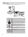
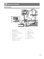
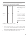
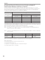
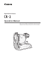
Digital Retinal Camera
Operation Manual
Make sure you read this manual before using the instrument.
Keep this manual safely so that you can use it in the future.
Thank you for purchasing the Canon Digital Retinal Camera CR-2 (referred to as “CR-2” in this
manual). The operation manuals for this instrument consist of the “Digital Retinal Camera CR-2
Operation Manual” and the “Retinal imaging control software NM 2 Operation Manual.” Be sure to
read these manuals thoroughly before using the instrument, and apply the information that you learn.
Important
• The CR-2 must only be used by a doctor or a legally qualified person.
• The user is responsible for managing the usage and maintenance of medical equipment. We
suggest that someone be put in charge of maintenance to ensure that the CR-2 is kept in good
condition and can be used safely.
Disclaimers
• Canon takes no responsibility for damage that occurs due to fires, earthquakes, third party
actions, other accidents, the user's deliberate misuse, negligence, experimentation, or use under
other abnormal conditions.
• Canon takes no responsibility for direct or consequential damages resulting from the use or the
inability to use the CR-2. In addition, no compensation is available for lost image data, regardless
of the cause of the loss of the image data.
• Canon takes no responsibility for injuries or property damage that may occur if safety precautions
are not followed or the instrument is used for something other than its intended purpose.
• Medical examinations are the responsibility of a doctor. Canon takes no responsibility for
diagnostic results.
• Follow the laws relating to the production, processing, analysis, and storage of medical images.
The user is responsible for maintaining the confidentiality of image data.
• The information in this manual may be changed without prior notice.
• Although we have made every effort to ensure the accuracy of the information in this manual, if you
have any queries regarding the contents, please contact the Canon representative or distributor
from whom you purchased the CR-2.
Installation
• Ask the Canon representative or distributor from whom you purchased the CR-2 to install it.
Trademarks
• Canon and the Canon logo are trademarks of Canon Inc.
• Other system names and product names that appear in this manual are trademarks of their
respective companies.
Copyright
• The copyright of this manual belongs to Canon Inc.
• Unauthorized reproduction, duplication, or reprinting of this manual in whole or in part is
prohibited.
2
Contents
1 Introduction.................................................................................................. 4
Features....................................................................................................... 4
Indications for Use...................................................................................... 4
Components . ............................................................................................. 5
Conventions Used in This Manual ............................................................. 6
2 Safety............................................................................................................ 7
Regulatory Information................................................................................ 7
Safety Precautions...................................................................................... 9
Notes on Using CR-2 ............................................................................... 13
Rating Label Display................................................................................. 16
3 Names of Parts.......................................................................................... 17
Retinal Camera . ....................................................................................... 17
Operation Panel ....................................................................................... 19
Observation Monitor................................................................................. 20
4 Basic Operations....................................................................................... 21
Flow of Operation . ................................................................................... 21
Connecting Cables . ................................................................................. 22
Preparing for an Examination ................................................................. 22
Setup for Patient ...................................................................................... 24
Alignment ................................................................................................. 25
Photography.............................................................................................. 28
Finishing an Examination ......................................................................... 29
5 Photography Auxiliary Functions............................................................ 30
x2 Photography......................................................................................... 30
Small Pupil Photography Function............................................................ 30
Diopter Compensation.............................................................................. 31
Anterior Eye Photography......................................................................... 32
External Monitor........................................................................................ 32
6 Maintenance............................................................................................... 34
Maintenance and Inspection . .................................................................. 34
Cleaning the Objective Lens .................................................................... 35
Cleaning the Image Sensor . .................................................................... 36
Cleaning the Outside of the CR-2 ............................................................ 36
Disinfecting the Forehead Rest................................................................. 37
Refilling Chin Rest Paper.......................................................................... 37
Attaching and Removing the Digital Camera .......................................... 37
7 Troubleshooting......................................................................................... 40
Appendix........................................................................................................ 42
Specifications . ......................................................................................... 42
EMC (Electromagnetic Compatibility)....................................................... 43
Warranty and Repair Service ................................................................... 47
3
1
Introduction
Features
The Canon Digital Retinal Camera CR-2 takes digital photographic retinal images of patient’s eyes
across an angle of view of 45 degrees, in a naturally dilated state without using mydriatics. The CR-2
has the following features.
Reduced flash intensity
The CR-2 can take images at ISO 1600 at the standard flash intensity, and ISO 6400 in low flash
intensity mode. This reduces patient discomfort caused by light glare.
Compact, user-friendly design
The CR-2 is designed to be even smaller, more lightweight and compact. This makes it easier to
assist patients and provides significantly improved ease-of-operation.
An integrated operation lever has been adopted for vertical movement of the main unit, switching
between anterior eye and retina, and focus operations, which significantly improves alignment
operability.
Special digital camera
The CR-2 is equipped with a special digital camera using EOS digital technology. This enables the
CR-2 to fully maximize Canon technology for shooting high-quality, high-resolution diagnostic images.
Small pupil photography function
The CR-2 take retinal images through pupils of the normal diameters from 4.0 mm. When using the
small pupil photography function, it can take through pupils of the diameters from 3.3 mm.
System optimized for digital photography
With the Retinal imaging control software, the photographed images can be browsed, processed,
stored, output to the DICOM storage server, exported in DICOM or JPEG format and output to a
printer.
Indications for Use
For U.S.A.
The device is intended to be used for taking digital images of the retina of the human eye without a
mydriatic.
For European Union
This medical device is intended to observe image and record retinal fundus through the pupil
without contact with subject’s eye for the purpose of diagnosis by way of producing fundus image
information.
4
1 Introduction
Components
Digital Retinal Camera CR-2
Main unit
Video cable
Use to connect an external
monitor.
Digital camera
Digital camera specialized for
the CR-2.
Digital camera cover
Protects the cable that is
connected to the digital
camera.
Power cord
Connects the CR-2 to an AC
outlet. (3 m)
USA and Canada only:
Plug type: VM0275 HospitalGrade
Chin rest paper
100 sheets provided.
Camera mount cap
Initially covers the camera
mount on the retinal camera.
Objective lens cap
Initially covers the objective
lens.
Dust cover
Use it to cover the CR-2 when
it's not being used.
Body cap
Initially covers the mount on
the digital camera.
Operation Manual for the CR-2—this document
Describes the handling precautions and operating instructions for the CR-2.
CD-ROM—Retinal imaging control software NM 2
Contains the Retinal imaging control software NM 2 (Rics NM 2), which is used to record, view and
store photographed images taken with the CR-2.
Operation Manual for the Retinal imaging control software NM 2
Describes the procedures for operating the Rics NM 2.
DICOM Conformance Statement
DICOM Conformance Statement for the Rics NM 2.
Optional products
External eye fixation lamp
Chin rest paper—500 sheets
5
1 Introduction
Conventions Used in This Manual
This manual uses the following symbols to indicate safety precautions that are important for using the
CR-2 safely. Always follow the advice in these safety precautions.
WARNING
CAUTION
CAUTION
A warning that incorrect operation may result in death or serious injury.
A caution that incorrect operation may result in serious injury.
A caution that incorrect operation may break the CR-2 or damage other
devices.
This symbol indicates things that must not be done (prohibited actions).
This symbol indicates things that must be done.
This symbol indicates important advice that we strongly recommend be
followed while operating the CR-2.
This symbol indicates supplementary explanations or advice for operating the
CR-2.
6
2
Safety
Regulatory Information
The following sections list the classifications applicable to the CR-2 and the directives and standards
that the CR-2 complies with.
Device Classification
Protection against electric shock
Class I equipment
Degree of protection against electric shock
Type B applied parts
Degree of protection against ingress of water
IPX0
Degree of safety of application in the presence of a
flammable anaesthetic mixture with air or with oxygen or
nitrous oxide
Not suitable
Mode of operation
Continuous operation
Directives and Standards
USA and Canada
UL 60601-1
CAN/CSA C22.2 No.601.1
IEC 60601-1: 1988/A1: 1991/A2: 1995
Medical electrical equipment – Part 1: General requirements
for safety
IEC 60601-1-1 Ed. 2.0: 2000
Medical electrical equipment – Part 1-1: General
requirements for safety – Collateral standard: Safety
requirements for medical electrical systems
IEC 60601-1-2: Ed. 2.1: 2004
Medical electrical equipment – Part 1-2: Collateral standard:
Electromagnetic compatibility – Requirements and tests
IEC 60601-1-4: Ed. 1.1: 2000
Medical electrical equipment – Part 1-4: Collateral standard:
Programmable electrical medical systems
ISO 15004-1: 2006
Ophthalmic instruments – Part 1: General requirements
applicable to all ophthalmic instruments
ISO 15004-2: 2007
Ophthalmic instruments – Part 2: Light hazard protection
ISO 10993-1: 2003
ISO 10993-5: 1999
ISO 10993-10: 2002/A1: 2006
Biological evaluation of medical devices – Evaluation and
testing
7
2 Safety
European Union
93/42/EEC
Medical Device Directive
EN 60601-1 Ed. 3.0: 2006
Medical electrical equipment – Part 1: General requirements
for safety
EN 60601-1-2: 2007
Medical electrical equipment – Part 1-2: Collateral standard:
Electromagnetic compatibility – Requirements and tests
EN 60601-1-6: 2004
Medical electrical equipment – Part 1-6: General
requirements for safety – Collateral standard: Usability
IEC 62304: 2006
Medical device software – Software life-cycle processes
EN 62366: 2008
Medical device – Application of usability engineering to
medical devices
EN ISO 14971: 2007
Medical device – Application of risk management to
medical devices
EN ISO 15004-1: 2006
Ophthalmic instruments – Part 1: General requirements
applicable to all ophthalmic instruments
EN ISO 15004-2: 2007
Ophthalmic instruments – Part 2: Light hazard protection
EN ISO 10993-1: 2003
EN ISO 10993-5: 1999
EN ISO 10993-10: 2002/A1: 2006
Biological evaluation of medical devices – Evaluation and
testing
Deutschland
Während des Betriebs liegt der Schalldruckpegel dieses Instruments bei 70 dB(A) oder weniger
gemäß EN ISO 7779.
8
2 Safety
Safety Precautions
To prevent injuries and data loss, operate the CR-2 correctly by following the safety precautions.
Do not damage the power cord
WARNING
Prohibited
• Do not place anything heavy onto the power cord.
• Do not damage or modify the power cord.
• Do not forcibly bend, twist or pull the power cord.
• Do not hold the power cord when removing it from the AC outlet. Be sure to hold
the plug.
• Do not use an extension cable with the power cord. Connect it directly to the AC
outlet.
Handle the power cord carefully. If the cord is damaged, contact a Canon
representative or distributor for a replacement. Damaged cord may result in fire or
electric shock.
Do not disassemble or modify
Prohibited
Disassembled or modified instrument may result in fire or electric shock. Since the
CR-2 incorporates high-voltage parts that may cause electric shocks, touching
them may cause death or serious injury.
Do not leave alcohol, thinner, or any flammable chemicals
near the instrument.
Prohibited
Do not place near to a flammable solvent. Fire may result if the solvent spills or
evaporates and makes contact with internal electric parts. Some disinfectants are
flammable. Be sure to take care when using them.
Stop using immediately if there is an abnormality or problem
If an abnormality occurs, immediately unplug the power plug
and turn off the power of all the devices
• Smoke is emitted
• An unusual smell
• An unusual noise
• Foreign matter gets inside
• Damaged
Fire or electric shock may result if you keep using in such condition. Immediately
turn off the power of CR-2, unplug the power plug and turn off the power of all
connected devices. Then, contact a Canon representative or distributor.
Do not place anything on top
Prohibited
Prohibited
Fire or electric shock may result if water or any other liquid or a needle, paper clip or
any foreign matter gets inside the CR-2.
Do not use a power supply voltage other than that specified
on the rating label
Do not use any power cord other than the supplied
Use the power voltage specified on the rating label. Otherwise, fire or electric shock
may result.
The supplied power cord is designed exclusively for this product. Do not use any
other power cord.
9
2 Safety
Do not plug or unplug the power plug with wet hands
WARNING
Prohibited
Do not plug or unplug the power plug or handle any other parts with wet hands.
Otherwise, fire or electric shock may result.
Unplug the plug periodically and remove any dust or dirt
around the plug and the AC outlet
If the cord is kept plugged in for a long time in a dusty, humid or sooty place, dust
around the plug will attract moisture, and this may cause insulation failure which
may result in a fire.
Insert the power plug completely
Insert the power plug completely into the AC outlet. If a pin of the power plug makes
contact with metal or any conductive object, fire or electric shock may result.
Do not clean the CR-2 with flammable solvent
Prohibited
Before cleaning the CR-2, for safety reasons, be sure to turn off the power of all the
devices and unplug the power cord from the AC outlet. Do not use alcohol, benzine,
thinner or any other flammable solvent.
Otherwise, fire or electric shock may result.
Turn off the power before inspection
Before inspecting the instrument or cables, for safety reasons, be sure to turn off
the power of all the devices.
Otherwise, it may result in electric shock.
Do not play the supplied CD-ROM in any CD Player
unsupporting data CD-ROMs
Prohibited
Playing the CD-ROM in an audio CD player may damage the speaker. It is also
possible to suffer hearing loss from listening with headphones to the loud sounds of
the CD-ROM on an audio CD player.
Do not install in locations exposed to water, steam, moisture
or dust
CAUTION
Prohibited
Doing so may cause problems or malfunctions.
Do not install in locations exposed to salt, sulfur or corrosive
gas
Prohibited
Doing so may result in corrosion of the instrument, problems or malfunctions.
Do not install in locations that are unstable or exposed to
vibration
Prohibited
The vibration may knock over the instrument or the instrument may lose its balance
and fall, resulting in a malfunction or injury.
Do not place anything near the power plug
Prohibited
To make it easy to unplug the power plug at any time you want, avoid putting any
obstructions near the AC outlet.
The power plug left plugged in an emergency may result in fire or electric shock.
Do not block the vent holes
Prohibited
10
Doing so may cause the internal temperature to rise and result in fire.
2 Safety
Do not place your hands or fingers on the base
CAUTION
Prohibited
Your hand or fingers may be pinched and injured when the stage moves to either
side.
Similarly, instruct the patient not to place the patient’s hands and fingers there.
Be sure to turn off the power before moving the CR-2
Before moving the CR-2, make sure that the power is turned off, the power plug is
unplugged from the AC outlet, and any cables that are connected to other devices
are disconnected.
Do not hold the face rest or digital camera when moving the
CR-2
Prohibited
When carrying the CR-2, be sure to tighten the stage lock, hold the carrying
indentations at the front and rear of the base panel, and keep the CR-2 level. Do not
hold it by the digital camera or the face rest or any other parts, as they may come
off and result in injury.
Hold the CR-2 when connecting or disconnecting a cable
When connecting or disconnecting the power cord or any cable, for safety reasons,
be sure to hold the main unit. Otherwise, the main unit may fall over, possibly
causing injury.
Ensure that the entire system conforms to IEC 60601-1-1
Use the computer, monitor, and other equipment that conform to the system
standard IEC 60601-1 or IEC 60950-1 for the Digital Retinal Camera CR-2. Be sure
that the entire system conform to IEC 60601-1-1. Be sure to also use an isolation
transformer conforming to IEC 60601-1 when a computer or monitor conforming to
IEC 60950-1 is used.
Otherwise, it may result in electric shock. For details, please contact a Canon
representative or distributor.
Keep the forehead rest and chin rest clean
To prevent the risk of infection, wipe the forehead rest with ethanol solution or any
other disinfectant whenever changing patients. To ensure cleanliness, replace the
chin rest paper whenever the patient is changed. If the chin rest paper is not being
used, be sure to disinfect the chin rest whenever the patient is changed.
For details on how to disinfect, consult a specialist. The forehead rest may be
corroded if a disinfectant other than those above is used or if another disinfectant is
added to ethanol. Consult a specialist in this case as well.
Slowly move the main unit towards the patient’s eye when
taking an image
When adjusting the position of the main unit in the front-back direction, slowly bring
the main unit closer to the patient while looking at the patient’s eye from the side.
The patient’s eye may be injured if the objective lens makes contact with it.
Check the image before using the CR-2
Before using the CR-2, be sure to take a test image to ensure that there is no foreign
matter present that can affect image readings or diagnosis.
11
2 Safety
Be sure to turn off the power when not in use
CAUTION
For safety reasons, be sure to turn off the power of all the devices when the CR-2 is
not being used.
Also, unplug the power plug from the AC outlet and put on the cover when the CR-2
is not going to be used for a long time.
Otherwise, dust or any foreign matter may accumulate and result in fire.
Do not touch the main unit and the chin rest while they are
moving
CAUTION
Prohibited
The main unit and the chin rest move to the center position when the CR-2 main
unit is turned on or a study is finished with the control software. Do not touch
the main unit and the chin rest while they are moving. At the same time, keep the
patient’s chin away from the chin rest.
Before packing the CR-2, return the main unit and chin rest to
their initial positions
Lower the main unit and chin rest to the bottom. To automatically lower them, turn
on the power while holding down the set button.
Inspect daily and regularly
Before using the CR-2, for safety reasons, be sure to perform the daily inspection.
Have a regular inspection performed for the CR-2 at least once a year at the
representative designated by Canon.
12
2 Safety
Notes on Using CR-2
Digital camera
• The attached digital camera is designed for the CR-2. The specifications differ from commercially
available Canon digital cameras, so it can be used only for observing and taking photographs of
peoples' eyes. Do not use the digital camera separately detaching from the main unit or it may
cause failure on the CR-2.
• If any problems with the CR-2's digital camera occur or repairs are needed, contact the Canon
representative or distributor from whom you purchased the CR-2.
Before use
• Inspect the CR-2 every day, make sure that no foreign matter is present that can affect image
readings or diagnoses.
• Check and clean the objective lens before taking an image. Any stains or scratches on the
objective lens will appear as white spots.
• Sudden heating of a room during winter or in cold regions may cause condensation to form on the
objective lens or on optical parts inside the CR-2. In this case, wait until condensation disappears
before taking images.
• Do not touch the lens part of the retinal camera or the mirror part of the digital camera when
attaching and detaching the digital camera from the retinal camera. If any dirt, fingerprints, dust, or
other foreign object is on the lens or mirror, you cannot take a good image.
After use
• After using the CR-2, turn off the power, cover the objective lens with the objective lens cover to
protect it from dust, and place the dust cover over the CR-2. You cannot take good images if the
objective lens is dusty.
• If the digital camera is detached and left unattached, dirt and dust may enter the retinal camera
and the digital camera. Be sure to always attach the caps to the respective mounts.
Cleaning and disinfection
• Do not allow the blower to touch the lens.
• Do not wipe or rub the lens if there is dirt or dust on it. Doing so could scratch the lens.
• Do not wipe the lens with ethanol solution, eyeglass cleaner, or silicone-coated paper. Doing so
could corrode the surface of the lens or leave streaks.
• Do not clean the outside of the CR-2 with lens cleaner. Doing so could damage the outside of the
CR-2.
• Never use alcohol, benzine, thinner, or other solvents to clean the outside of the CR-2. Doing so
damages the outside of the CR-2.
• Never use ethanol solution to clean the outside of the CR-2, except the forehead rest and the chin
rest. Doing so damages the outside of the CR-2.
• If the chin rest paper is not being used, disinfect the chin rest for each patient in the same way as
the forehead rest.
13
2 Safety
Environment of use
• Use, store, and transport the CR-2 in an environment that is within the range of the following
conditions.
Temperature
Environment of use
10 to 35°C
Storage and transportation –30 to 60°C
environment
Humidity
Atmospheric pressure
30 to 90% RH (no
condensation)
800 to 1060 hPa
10 to 60% RH (no
condensation)
700 to 1060 hPa
• Do not install, store, or leave the CR-2 in a very hot or humid environment. Also, do not use the
CR-2 outside. Doing so may cause a malfunction or misoperation.
• Always try to keep the room as clean as possible. After many years of usage, airborne dust in the
room may get on the objective lens as well as the optical parts in the main unit. You cannot take
good images if dust is on the equipment.
• When the CR-2 is not being used, attach the objective lens cap and place the dust cover over the
CR-2.
Installation
• Ask the Canon representative or distributor from whom you purchased the CR-2 to install it.
• A strong shock to the CR-2 may put it out of alignment. Please handle it carefully.
Transportation
• Lower the main unit and chin rest to the bottom. To automatically lower them, turn on the power
while holding down the set button.
• Be sure to turn off the CR-2's power switch, remove the AC plug from the outlet, and disconnect
any cables connected to other equipment.
• Align the stage with the base, and then lock the stage with the stage lock lever.
• Carry the CR-2 by the indentations for lifting at its front and rear, and keep it level.
• Do not hold the face rest or digital camera when lifting the main unit.
• The CR-2 needs to be protected from vibration and shocks when it is transported in a vehicle or
over long distances. For details, contact the Canon representative or distributor from whom you
purchased the CR-2.
14
2 Safety
Disposal
Disposal of this product in an unlawful manner may have a negative impact on health and on the
environment. When disposing of this product, therefore, be absolutely sure to follow the procedure
which is in conformity with the laws and regulations applicable in your area.
European Union (and EEA*) only
This symbol indicates that this product is not to be disposed of with your
household waste, according to the WEEE Directive (2002/96/EC) and your national
law. This product should be handed over to a designated collection point, e.g.,
on an authorized one-for-one basis when you buy a new similar product or to an
authorized collection site for recycling waste electrical and electronic equipment
(EEE). Improper handling of this type of waste could have a possible negative
impact on the environment and human health due to potentially hazardous
substances that are generally associated with EEE. At the same time, your
cooperation in the correct disposal of this product will contribute to the effective
usage of natural resources. For more information about where you can drop off
your waste equipment for recycling, please contact your local city office, waste
authority, approved WEEE scheme or your household waste disposal service.
For more information regarding return and recycling of WEEE products, please visit
www.canon-europe.com/environment.
* EEA: Norway, Iceland and Liechtenstein
For California, USA Only
Included battery contains Perchlorate Material—Special handling may apply.
See http://www.dtsc.ca.gov/hazardouswaste/perchlorate/ for details.
15
2 Safety
Rating Label Display
The position and contents of the label attached on the CR-2 is shown below.
Follow the information on the label to use the CR-2 appropriately.
The following table describes the marks and indications on the rating label.
Alternating current
Type B
Class I device indicating manufacturer’s declaration of conformance
with the Annex VII of the Medical Device Directive, 93/42/EEC
Certification mark that shows the product has passed the tests by
TUV Rheinland of conformity with the medical device regulations in the
European Union.
Product that WEEE directive, Directive on Waste Electrical and
Electronic Equipment, 2002/96/EC, requires separate collection. The
directive is effective in the European Union only.
Certification mark that indicates the product complies with UL 606011 and CAN/CSA 22.2 No. 601.1, that specifies protection against fire,
electric shock, and mechanical hazards
Caution: Grounding reliability can only be achieved when the equipment
is connected to an equivalent receptacle marked “HOSPITAL GRADE”.
This caution applies to the USA only.
Caution: Federal law (USA) restricts this device to sale by or on the
order of a physician.
16
Year and Month of Production
Example: October 2010
Serial number in six digits
Example: 123456
3
Names of Parts
Retinal Camera
1
2
12
3
4
13
5
6
7
8
14
9
15
16
1
2
3
10
17
11
18
Digital camera
Digital camera cover
Observation monitor
For viewing the anterior eye and retina.
4
5
6
7
Power switch for the digital camera
Operation lever
Shutter release button
Alignment button
Switches between a view of the anterior eye and
the retina.
8
Main unit vertical movement ring
9
Focus ring
Turn to focus the image.
10
11
12
13
14
15
16
17
18
Stage lock
Indentation for lifting
Height adjustment mark
Main unit
Operation panel
USB connector
AC power connector
Power switch for main unit
Stage
Turn right: Main unit moves up.
Turn left: Main unit moves down.
17
3 Names of Parts
19
20
26
21
22
a
23
b
c
24
d
27
25
19
Connector for external eye fixation lamp
(with cap)
Connector for the external eye fixation lamp (sold
20
21
22
23
18
24
25
26
Chin rest
Indentation for lifting
Diopter compensation knob
separately).
a No diopter compensation
Forehead rest
Objective lens
Objective lens cap
Face rest
b Negative compensation
c Positive compensation
d Anterior eye photography
27
Base
3 Names of Parts
Operation Panel
1
2
6
3
4
7
5
8
1
2
Flash intensity button/lamp
5
Top: Raises chin rest.
–: Flash intensity decreases.
Bottom: Lowers chin rest.
Observation light brightness button/lamp
6
+: Observation light brightness increases.
x2 photography button/lamp
7
Small pupil photography button/lamp
Enables small pupil photography function. (See
Set button/lamp
Internal eye fixation lamp blinks.
Enables x2 photography function. (See page 30)
4
FIX TARGET button
Move up, down, right, and left to move internal eye
fixation lamp.
–: Observation light brightness decreases.
3
CHIN REST button
+: Flash intensity increases.
8
POWER lamp
Lights when power is turned on.
page 30)
19
3 Names of Parts
Observation Monitor
During anterior eye observation
1
2
1
4
2
5
3
6
Pupil alignment circles
Photography ready lamp
4
Green: Ready to shoot
Red: Not ready to shoot
3
Left/right eye indicator
R: Right eye
L: Left eye
5
Observation light brightness indicator
Diopter compensation knob position
indicator
: Anterior eye photography
6
Flash intensity indicator
During retinal observation (with x1.3 magnification)
1
7
8
2
9
3
10
4
5
11
6
1
Indicator for top limit of position of main
unit
7
8
Appears when main unit has reached top limit.
2
3
4
Focus indicator
WD guide (green)
Indicator for bottom limit of position of
main unit
Appears when main unit has reached bottom limit.
5
6
20
x2 photography indicator
Small pupil photography indicator
x2 photography range
Diopter compensation knob position
indicator
None: No diopter compensation
+: Positive compensation
–: Negative compensation
9
10
11
Small pupil photography range
Internal eye fixation lamp position indicator
Focus lens position indicator
4
Basic Operations
Flow of Operation
The flow of operations for retinal photography is as follows.
Connect the cables if necessary as described in “Connecting Cables” (see page 22).

Preparing for an examination (page 22)
Setup for patient (page 24)
Alignment (page 25)
Small pupil photography (page 30)
x2 photography (page 30)
Diopter compensation (page 31)
Anterior eye photography (page 32)
Photography (page 28)
Finishing an examination (page 29)
21
4 Basic Operations
Connecting Cables
Connect the CR-2 to a computer in which the Rics NM 2, the supplied software, has been installed.
WARNING
• Do not plug or unplug the power plug with wet hands.
• Do not use any power cord other than the supplied.
Otherwise, fire or electric shock may result.
1 Make sure that the power switch for the CR-2 is turned off.
the power cord and the USB cable to the
2 Connect
retinal camera.
3 Insert the power plug all the way into an AC outlet.
4 Connect the other end of the USB cable to the USB connector of the PC.
Use a high-speed AB type USB cable that is 3 meters or shorter. For details, contact the Canon
representative or distributor from whom you purchased the CR-2.
Preparing for an Examination
CAUTION
• To prevent the risk of infection, wipe the forehead rest with ethanol solution or any other
disinfectant whenever changing patients. For details on how to disinfect, consult a specialist.
• To ensure cleanliness, replace the chin rest paper whenever the patient is changed.
1 Turn on the computer and start the Rics NM 2.
digital camera is off, turn the switch to the ON or
2 If theposition.
22
4 Basic Operations
the objective lens cap, and turn the retinal
3 Remove
camera's power switch to the ON position.
The POWER lamp lights and the set lamp blinks.
The CR-2 automatically does an initialization sequence (internal
check and initialization of driving parts). After the initialization
the parts of the main unit stop in their center positions.
CAUTION
The main unit and the chin rest move to the center position when the CR-2 is turned on. Do not
touch the main unit and the chin rest while they are moving. At the same time, keep the patient’s
chin away from the chin rest.
Power-saving function
If the power is on and the buttons on the operation panel are not operated for over 10 minutes, the
power-saving function is activated. The POWER lamp blinks while in power saving mode.
To return to normal mode, press any button on the operation panel, move the stage right or left, or
turn the diopter compensation knob.
sure the diopter compensation knob is in the 0
4 Make
position.
You can also check the position of the diopter compensation knob on the observation monitor.
and hold the unlock button and slide the stage
5 Press
lock to the UNLOCK side.
Align the mark on the stage lock and the mark on the left side
of the base.
The stage lock is released.
6 Move the stage towards you with the operation lever.
23
4 Basic Operations
7 Disinfect the forehead rest and replace the chin rest paper.
If chin rest paper is not being used, disinfect the chin rest also.
CAUTION
• To prevent the risk of infection, wipe the forehead rest with ethanol solution or any other
disinfectant whenever changing patients. For details on how to disinfect, consult a specialist.
• To ensure cleanliness, replace the chin rest paper whenever the patient is changed.
Setup for Patient
1 Start an examination on the Rics NM 2.
Enter the patient’s information.
The set lamp lights and the observation monitor turns on.
2 Seat and position the patient.
• Instruct the patient to remove their contact lenses or glasses, if they are wearing them.
• Have the patient place their chin on the chin rest and their forehead against the forehead rest.
Adjust the heights of the optical bench and chair so the patient is comfortable.
the chin rest with the CHIN REST button so that the patient's eye is aligned with
3 Move
the height adjustment mark.

Height adjustment
mark
Chin rest rises
Chin rest lowers
4 Move the stage toward the eye to be photographed.
CAUTION
• Do not place your hands or fingers on the base.
• Instruct the patient not to place the patient’s hands and fingers there.
Otherwise, your or the patient’s hands or fingers may be pinched, possibly resulting in injury.
Hold the operation lever, pull it toward you, and then move the
stage.
24
4 Basic Operations
Alignment
1 Align the retinal camera with the eye to be photographed.
CAUTION
When adjusting the position of the retinal camera in the front-back direction, slowly bring the main
unit closer to the patient while looking at the patient’s eye from the side. The patient’s eye may be
injured if the objective lens makes contact with it.
1. Move the stage until the eye to be photographed appears in the observation monitor.
2. Adjust the center of the patient's pupil and the pupil alignment circles.
3. Have the patient stare at the green blinking internal eye fixation lamp.
Pupil alignment circles
When examining the anterior eye of a patient who is extremely near or far sighted, the patient may
not be able to see the internal eye fixation lamp.
• To move the main unit slightly to the left or right, tilt the
operation lever to the left or right.
• To move the main unit slightly to the front or back, tilt the
operation lever to the front or back.
• To move the main unit up or down, turn the main unit
vertical movement ring.
When the vertical position cannot be fully adjusted by using the operation lever
Adjust the height of the chin rest with the CHIN REST button to raise or lower the patient's face.
25
4 Basic Operations
the operation lever forward or backward to unify the top and bottom of the image of
2 Tilt
the pupil.
When the pupil is smaller than the inner pupil alignment circle
Darken the room further to dilate the patient's pupil more. If the patient's pupil does not dilate
enough, use the small pupil photography function (see page 30).
3 Press the alignment button.
The retina appears in the observation monitor and the internal
eye fixation lamp blinks for three seconds.
the observation light brightness with the
4 Adjust
observation light brightness button.
Guidelines for observation light brightness
Adjust to the lowest possible brightness level to reduce the strain on the patient's eye.
Observation monitor brightness adjustment
Use the Rics NM 2 to adjust the brightness of the observation monitor. See the Rics NM 2 manual
for details.
26
4 Basic Operations
5 Have the patient stare at the internal eye fixation lamp to fix the part for the photograph.
Take the following steps to guide the patient’s eye. Press the FIX TARGET buttons up, down, left, and
right to move the internal eye fixation lamp to your desired position and then press the set button
to make it blink. If the eye cannot be guided by the internal eye fixation lamp, use the external eye
fixation lamp (sold separately).
Set button
Press the set button for over two seconds to reset the position of the internal eye fixation lamp.
See the Rics NM 2 manual for details.
6 Turn the focus ring to align the split lines into a single line.
The image enlarges while the focus ring is being turned.
Split line
Correct
Incorrect
Incorrect
Focus ring
When the split lines do not align
If the patient's diopter range is outside the –10 to +15 D, it is not possible to focus with the focus
indicator. If this happens, use the diopter compensation function (see page 31), and focus the image
so it looks sharp.
27
4 Basic Operations
Photography
1 Do a preliminary check before taking photos.
a.
b.
c.
d.
The photography ready lamp lights green.
The working distance dots appear sharpest.
The working distance dots are on the extension line of the WD guides.
The split lines form a single line.
a
b, c
d
Photography ready lamp
• Green: Ready to shoot.
• Red: Preparing to shoot. Wait until the lamp lights green.
• None: Cannot access the Rics NM 2. The retina observation mode is not established.
Flash intensity adjustment
The flash intensity is set to the standard level in advance.
Every time the flash intensity button is pressed the flash
intensity increases by 0.3 stop.
2 Press the shutter release button.
The image of the retina and the examination information appear on the Rics NM 2 screen.
3 Check the photographed image.
Check that the image is normal and there are no errors in the examination information.
To take images of the other eye, repeat steps from step 1 of Alignment (see page 25).
28
4 Basic Operations
Finishing an Examination
1 Save the images on the Rics NM 2 and end the examination.
The set lamp starts blinking and the observation monitor turns off.
CAUTION
The main unit and the chin rest moves to the center position when a study is finished with the
control software. Do not touch the main unit and the chin rest while they are moving.
the stage with the base and slide the stage lock
2 Align
to LOCK side to lock the stage.
Align the mark on the stage lock and the mark on the right side
of the base.
3 Turn off the power to the CR-2.
4 Exit the Rics NM 2 and turn off the computer.
29
5
Photography Auxiliary Functions
The section describes how to use x2 photography, small pupil photography function, diopter
compensation, and anterior eye photography and how to connect an external monitor when one is
used.
x2 Photography
You can take and save images that are within the x2 photography range on the observation monitor.
1 Press the x2 photography button.
The lamp on the x2 photography button lights, and the x2 photography indicator and x2 photography
range marks appear on the observation monitor.
x2 photography
range mark
x2 photography
indicator
2 Take the image.
The image in the x2 photography range appears on the Rics NM 2 screen.
Small Pupil Photography Function
If the diameter of the patient’s pupil is smaller than the inner pupil alignment circle after waiting for
a while in a dark room, use the small pupil photography function. When the function is used, pupil
diameters 3.3 mm or larger can be photographed.
1 Press the small pupil photography button.
The lamp on the small pupil photography button lights, and the small pupil photography indicator and
a dotted circle appear on the observation monitor.
Effective range of
photography
Small pupil
photography indicator
30
5 Photography Auxiliary Functions
2 Take the image.
Press the small pupil photography button again to finish the small pupil photography.
• Do not use the small pupil photography function if the patient's pupil is large enough. The image
will be overexposed.
• The image may contain flare around the edges of the image outside the photography range.
Diopter Compensation
If because of the patient's diopter the image cannot be brought into focus by turning the focus ring,
use the diopter compensation knob to change the position. Insert the diopter compensation lens into
the CR-2 and take the photograph.
Diopter compensation mark
0
Negative
Positive
The CR-2 can provide appropriate images if the diopter of the patient’s eye fall within each range
below.
• 0 position: –10 to +15 D
• – position: –31 to –7 D
• + position: +11 to +33 D
Note that when the diopter compensation knob is set to the – or + position, the focus indicator does
not appear. Turn the focus ring to focus the retinal image in a position that brings the image clear on
the observation monitor.
When operating the diopter compensation knob, set it precisely to the 0, –, or + position. If the
knob is not aligned with the position noted above, the retinal image is not captured correctly.
31
5 Photography Auxiliary Functions
Anterior Eye Photography
This function makes it possible to photograph the anterior eye. It is also possible to use the x2
photography function at the same time.
Do not allow external light that contains infrared to enter the position being photographed.
1 Switch the diopter compensation knob to the anterior eye photography position.
The anterior eye photography mark appears on the observation monitor.
Photography
ready lamp
Anterior eye
photography mark
Anterior eye
photography
the operation lever to align the area to be photographed in the center of the
2 Move
observation monitor.
3 Tilt the operation lever to the front or back to focus on the area to be photographed.
• Focus the image so that the area to be photographed can be seen as clearly as possible.
• Make sure that the photography ready lamp lights green.
4 Press the shutter release button.
The image of the retina appears on the Rics NM 2 screen.
To take images of another position, repeat steps from step 2.
External Monitor
The image on the observation monitor can be viewed on an external monitor.
Contact the Canon representative or distributor from whom you purchased the CR-2 about which
external monitors can be used.
• Before connecting or disconnecting video cables, be sure to turn off the retinal camera and all
other devices.
• Use only the video cable provided with the instrument. Images might not be displayed if a
different video cable is used.
• Use an external monitor that conforms to IEC60601-1 or IEC60950-1. If you use a monitor that
conforms to IEC60950-1, be sure to also use the isolation transformer that is designated by
Canon. For details, contact the Canon representative or distributor from whom you purchased
the CR-2.
32
5 Photography Auxiliary Functions
1 Remove the digital camera cover.
2 Connect the video cable to the digital camera.
1. Securely insert the supplied video cable into the VIDEO OUT terminal on the digital camera.
2. Fit the ferrite core of the video cable into the space in the cover, and place the video cable in the
notch.
Notch
Ferrite core
3 Attach the digital camera cover.
1. Hook the digital camera cover hook onto the strap mount of the digital camera.
2. While taking care to avoid pinching the video cable, insert the cover screw to secure the digital
camera cover.
Cover screw
4 Connect the video cable to the external monitor.
Connect the video cable to the video input terminal (yellow) on the external monitor. Turn on the
external monitor, and select the input using the monitor's input switch.
Audio
Video input terminal
5 Turn on the power to the retinal camera and the digital camera.
The image is displayed on the external observation monitor. No image is displayed on the observation
monitor of the retinal camera.
33
6
Maintenance
This section describes the CR-2's daily inspections, cleaning, disinfection, as well as refilling the chin
rest paper, and removing and installing the digital camera.
CAUTION
• Before using the CR-2, for safety reasons, be sure to perform the daily inspection.
• Have a regular inspection performed for the CR-2 at least once a year by the representative that
is designated by Canon.
Maintenance and Inspection
Do the following inspections before using the CR-2 to insure that it is used safely and correctly.
If a problem is found during the inspection and you are unable to correct the problem, please contact
the Canon representative or distributor from whom you purchased the CR-2.
Checks before turning on the power
Check the following items before turning on the power.
Cables
1) The power cord and connection cable are not damaged and their insulation is not torn.
2) The power cord is fully and securely inserted into the AC connector on the main unit and the AC
outlet.
Main unit
1)
2)
3)
4)
5)
The digital camera cover and parts are not damaged or loose.
The stage moves smoothly when the operation lever is tilted back and forth and right to left.
The digital camera is securely installed.
The stage lock operates properly.
There are no scratches or dirt on the objective lens. Clean the objective lens if it is dirty (see page 35).
Checks after turning on the power
Turn on the CR-2 and start the Rics NM 2. Check the following items after starting an examination.
Main unit
1)
2)
3)
4)
5)
The power lamp lights.
The observation light brightness changes as the observation light brightness button is pressed.
A flash is emitted.
The main unit moves up and down smoothly as the main unit vertical movement ring is turned.
The chin rest moves up and down smoothly as the CHIN REST button is pressed.
Photographed image
1) Foreign object that affects the reading of the images or diagnosis does not appear in the
photographed image. Place a piece of white paper in front of the objective lens and photograph
an image under the following conditions.
• Flash intensity: Standard
• Diopter compensation knob: 0
• Focus ring: Turned clockwise more than 1 rotation.
34
6 Maintenance
Cleaning the Objective Lens
• Do not wipe or rub the objective lens if there is dirt or dust on it. Doing so could scratch the
surface of the lens.
• Do not wipe the objective lens with disinfectant ethanol, eyeglass cleaner, or silicone-coated
paper. Doing so could corrode the surface of the lens or leave streaks.
For information about lens cleaning paper, lens cleaner, and blowers, contact the Canon
representative or distributor from whom you purchased the CR-2.
If the objective lens is dirty, clean it according to the procedure below.
1 Check for any dirt.
Illuminate the objective lens with a penlight to check for dirt.
2 Blow away any dust or dirt.
Use a blower to blow away any dust or dirt on the lens. Do not
use a brush to dust off.
Do not allow the blower to touch the objective lens.
3 Wipe the objective lens.
1. Slightly dampen a lens cleaning paper with lens cleaner
and lightly wipe the objective lens.
2. Starting from the center of the lens, wipe the lens in spirals
toward the circumference.
3. Change the lens cleaning paper and wipe the objective
lens until the dirt is gone and there are no streaks.
Use lens cleaning paper and lens cleaner designated by Canon.
35
6 Maintenance
Cleaning the Image Sensor
The digital camera has a self-cleaning sensor unit. Dirt and dust on the front surface of the imaging
sensor are automatically removed when the power is turned on or off. This function makes it possible
to remove the majority of dirt and dust that may interfere with images. It is not necessary to be aware
of this function during normal usage.
To use the self-cleaning sensor unit for cleaning, follow the procedure below.
1 Make sure that the power switch for the retinal camera is turned off.
2 Switch the digital camera's power switch from on to off, or from
to off.
The self-cleaning sensor unit starts and the imaging sensor is cleaned.
3 Check that the dirt and dust have been removed.
the digital camera's power switch to on, photograph an image and check the
4 Switch
image.
If the above procedure does not remove the foreign object, the cause may not be dirt or dust.
Contact the Canon representative or distributor from whom you purchased the CR-2.
Cleaning the Outside of the CR-2
WARNING
• Before cleaning the CR-2, be sure to turn off the power of all the devices, and unplug the power
cord from the AC outlet.
• Do not use alcohol, benzine, thinner or any other flammable cleaning solvent.
Otherwise, fire or electric shock may result.
Do not clean the outside of the CR-2 with lens cleaner. It may corrode the material of the outside
of the CR-2.
If the outside of the CR-2 is dirty, wipe it twice with a soft cloth. First use a cloth that has been soaked
in diluted neutral cleanser and well wrung out. Then use a cloth that has been soaked in water and
well wrung out.
36
6 Maintenance
Disinfecting the Forehead Rest
CAUTION
• To prevent the risk of infection, wipe the forehead rest with ethanol solution or any other
disinfectant whenever changing patients.
• The forehead rest may be corroded if a disinfectant other than those above is used or if another
disinfectant is added to ethanol.
For details on how to disinfect, consult a specialist.
Use a sanitized gauze or wipe that includes disinfectant to clean the forehead rest for each patient.
Refilling Chin Rest Paper
CAUTION
If the chin rest paper is not being used, be sure to disinfect the chin rest whenever the patient is
changed. For details on how to disinfect, see the Disinfecting Forehead Rest section.
1 Pull out the right and left chin rest holding pins.
2 Insert the holding pins into the holes on the right and left of the chin rest paper.
the chin rest paper to the chin rest with the pins pressing into the holes on the
3 Attach
chin rest.
Chin rest paper is a consumable product (sold separately). To purchase chin rest paper, contact
the Canon representative or distributor from whom you purchased the CR-2.
Attaching and Removing the Digital Camera
The CR-2 is equipped with a specialized digital camera. It is not necessary to attach or remove the
digital camera during normal usage.
To replace the digital camera, follow the procedure below to remove and attach the digital camera.
Note the following points if it is necessary to remove and attach the digital camera.
• Work quickly in a location where there is little dust.
• When removing the digital camera for storage, be sure to attach the supplied camera mount cap
to the retinal camera and the body cap to the digital camera.
• Wipe off any dust from the camera mount cap and the body cap before attaching them.
• Do not touch the lens in the main unit or the mirror in the digital camera. It is not possible to take
good images if dirt, fingerprints, or dust on these parts.
37
6 Maintenance
Removing the digital camera
1 Turn off the power to the retinal camera and remove the plug from the AC outlet.
the cover screw and remove the digital camera
2 Loosen
cover.
the cables from the digital terminal and the
3 Remove
remote control terminal.
4 Remove the DC coupler.
1. Open the battery compartment cover on the digital
camera, and then slide the battery lock lever to remove the
DC coupler.
2. Close the battery compartment cover.
holding down the lens release button
5 While
on the digital camera, turn the digital camera
counterclockwise to remove it.
6 Attach the caps to the retinal camera and the digital camera mount.
38
6 Maintenance
Installing the digital camera
1 Make sure the following check items.
• The power to the retinal camera is off.
• The power plug of the retinal camera is not plugged into an electric outlet.
2 Attach the digital camera to the retinal camera.
1. Align the positions of the mounting alignment marks on the retinal camera and the digital camera.
2. Fit the digital camera's lens mount to the retinal camera's mount.
3. Turn the digital camera clockwise until it clicks.
Mounting alignment mark
3 Attach the DC coupler to the digital camera.
1. Open the battery compartment cover of the digital camera,
and attach the DC coupler.
2. Pass the cord for the DC coupler through the DC coupler
cord hole and then close the battery compartment cover.
the terminal cover of the digital camera and
4 Open
attach the cables to the digital terminal and the remote
control terminal.
5 Attach the digital camera cover to the digital camera.
1. Hook the digital camera cover hook onto the strap mount
of the digital camera.
2. Insert the cover screw to secure the digital camera cover.
39
7
Troubleshooting
If any of the symptoms listed here occurs or if a warning appears in the Rics NM 2 while using the
CR-2, try the relevant remedy described below.
If these remedies do not eliminate the symptoms or the warning, turn off the power and contact
the Canon representative or distributor from whom you purchased the CR-2. Be ready to provide a
detailed description of the symptoms and message.
Symptom
The power lamp does not light
when the power is turned on.
Cause and remedy
The power cord has been disconnected. Turn off the power to
the retinal camera and reconnect the power.
The power cord has been cut. Contact the Canon
representative or distributor from whom you purchased the CR2.
A buzzer sounds (pi-pi-pi) and the
A system error has occurred. Contact the Canon representative
operation panel lamps blink when
or distributor from whom you purchased the CR-2.
the power is turned on.
The observation monitor is dim
and hard to see.
Adjust the brightness of the observation monitor. See the Rics
NM 2 manual.
The observation monitor does not
Turn on the digital camera.
turn on.
An error appears (Err xx) on the
observation monitor.
The working distance dots are
hard to see.
The split lines are hard to see.
A malfunction has been detected in the digital camera. Turn off
the power to the retinal camera and then turn it on again.
The observation light is too bright. Reduce the observation light
brightness.
The working distance dots are not
The retinal camera and the eye are not aligned. Align them
visible.
correctly.
Flare is visible.
The patient's pupil is not dilated enough. Dilate the patient’s
pupil. If the pupil is still too small, enable the small pupil
photography function.
The split lines are not visible.
Eyebrows or eyelashes are blocking the pupil. Instruct the
patient to open their eye wider.
The patient's eye is cloudy. Focusing cannot be done with the
split lines.
The diopter compensation knob is set to either negative or
positive. Set it to the 0 position.
The split line lamps are not lit.
The split lines do not align.
40
The diopter patient's eye is outside the range of –10 to +15 D.
Use the diopter compensation function, turn the focus ring, and
focus on the position where the images of the retina look clear
at the same time.
7 Troubleshooting
Symptom
Cause and remedy
The patient's pupil is not dilated enough. Dilate the patient’s
pupil. If the pupil is still too small, enable the small pupil
photography function.
The retinal camera and the eye are not aligned. Align them
correctly.
Focus the image.
Cannot capture good images.
Eyebrows or eyelashes are blocking the pupil. Instruct the
patient to open their eye wider.
The patient's eye is cloudy. Clear images cannot be captured if
this is the case.
Adjust the flash intensity, patient's diopter, and small pupil
photography function.
The objective lens is dirty. Clean the objective lens (see page 35).
The patient is wearing contact lenses. Instruct the patient to
remove their contact lenses.
Black spots or any artifacts
appear in the same place in every
captured image.
White spots are visible on the
captured image.
There is dirt or dust on the objective lens. Clean the objective
lens (see page 35).
Dirt or dust is stuck to the imaging sensor of the digital camera.
Use the self-cleaning sensor unit to clean it. (see page 36).
The objective lens is dirty. Clean the objective lens (see page 35).
The patient's eyelashes are interfering with the image. Instruct
the patient to open their eye wider, and capture another image.
41
Appendix
Specifications
Field angle
45°
Photographic magnification
1.1 x (image size on the sensor)
Required pupil diameter
4.0 mm or greater (3.3 mm when using small pupil photography
function)
Working distance
35 mm
Focus adjustment range
–10 to +15 D (without compensation lens)
–31 to –7 D (when using negative compensation lens)
+11 to +33 D (when using positive compensation lens)
(Split-line alignment type focusing)
Flash intensity
Linked to the photography mode
Can be set manually
Light source
Observation light source
Infrared LED
Flash source
White LED
Camera
Digital camera
Eye fixation lamp
Internal eye fixation lamp (LED)
External eye fixation lamp (sold separately)
Range of motion
42
Stage
100 mm side to side, 70 mm front to back
Main unit vertical
movement
32 mm
Chin rest range of motion
60 mm
Power supply rating
AC 100 V to 240 V, 50/60 Hz, 1 A to 0.4 A
Dimensions
305 (W) × 500 (D) × 473 (H) mm
Weight
Approximately 15 kg (including 0.8 kg digital camera)
Appendix
EMC (Electromagnetic Compatibility)
This instrument conforms to the EMC standard IEC 60601-1-2.
Guidance and Manufacturer’s Declaration for Electromagnetic Emission
The CR-2 is intended for use in the electromagnetic environment specified below.
The customer or the user of the CR-2 should assure that it is used in such an environment.
Emission Test
Compliance
RF emissions
CISPR11
GROUP 1
RF emissions
CISPR11
Class B
Harmonic emissions
IEC 61000-3-2
Class A
Voltage fluctuations/flicker emissions
IEC 61000-3-3
Complies
Electromagnetic Environment – Guidance
The CR-2 uses RF energy only for its internal
function. Therefore, its RF emissions are very low
and are not likely to cause any interference in nearby
electromagnetic equipment.
The CR-2 is suitable for use in all establishments,
including domestic establishments and those directly
connected to the public low-voltage power supply
network that supplies buildings used for domestic
purposes.
43
Appendix
Guidance and Manufacturer’s Declaration for Electromagnetic Immunity
The CR-2 is intended for use in the electromagnetic environment specified below.
The customer or the user of the CR-2 should assure that it is used in such an environment.
IEC 60601
Test Level
Immunity Test
Electrostatic discharge
(ESD)
IEC 61000-4-2
±(2, 4, 6) kV contact
±(2, 4, 6) kV contact
±(2, 4, 8) kV air
±(2, 4, 8) kV air
±2 kV for power supply
Electrical fast transient/ lines
burst
±1 kV for input/output
IEC 61000-4-4
lines
Surge
IEC 61000-4-5
Voltage dips, short
interruptions and
voltage variations on
power supply input
lines
IEC 61000-4-11
Power frequency
(50/60Hz) magnetic
field
IEC 61000-4-8
Compliance Level
±1 kV differential mode
Floors should be wood, concrete or ceramic
tile.
If floors are covered with synthetic material,
the relative humidity should be at least 30%.
±2 kV for power supply
lines
Mains power quality should be that of a
typical commercial or hospital environment.
±1 kV for input/output
lines
±1 kV differential mode
±2 kV common mode
±2 kV common mode
<5% UT (>95% dip in
UT) for 0.5 cycles
<5% UT (>95% dip in
UT) for 0.5 cycles
3 A/m
3 A/m
Mains power quality should be that of a
typical commercial or hospital environment.
Mains power quality should be that of a
40% UT (60% dip in UT) 40% UT (60% dip in UT) typical commercial or hospital environment.
for 5 cycles
for 5 cycles
If the user of the CR-2 requires continued
70% UT (30% dip in UT) 70% UT (30% dip in UT) operation during power mains interruptions,
it is recommended that the CR-2 be powered
for 25 cycles
for 25 cycles
from an uninterruptible power supply.
<5% UT (>95% dip in
<5% UT (>95% dip in
UT) for 5 sec
UT) for 5 sec
NOTE: UT is the a.c. mains voltage prior to application of the test level.
44
Electromagnetic Environment – Guidance
Power frequency magnetic fields should be
at levels characteristic of a typical location in
a typical commercial or hospital environment.
Appendix
Guidance and Manufacturer’s Declaration for Electromagnetic Immunity
The CR-2 is intended for use in the electromagnetic environment specified below.
The customer or the user of the CR-2 should assure that it is used in such an environment.
Immunity Test
IEC 60601
Test Level
Compliance Level
Electromagnetic Environment – Guidance
Portable and mobile RF communications
equipment should be used no closer to any
part of the CR-2, including cables, than the
recommended separation distance calculated
from the equation applicable to the frequency
of the transmitter
Recommended Separation Distances
d = 1.2 √P
d = 1.2 √P 80 MHz to 800 MHz
d = 2.3 √P 800 MHz to 2.5 GHz
Conducted RF
IEC 61000-4-6
3 Vrms
150 kHz to 80 MHz
3 Vrms
Radiated RF
IEC 61000-4-3
3 V/m
80 MHz to 2.5 GHz
3 V/m
where P is the maximum output power rating
of the transmitter in watts (W) according to
the transmitter manufacturer and d is the
recommended separation distance in metres
(m).
Field strengths from fixed RF transmitters,
as determined by an electromagnetic site
surveya, should be less than the compliance
level in each frequency rangeb.
Interference may occur in the vicinity of
equipment marked with the following symbol:
NOTE 1:At 80 MHz and 800 MHz, the higher frequency range applies.
NOTE 2:These guidelines may not apply in all situations. Electromagnetic propagation is affected by absorption and
reflection from structures, objects and people.
a
b
Field strengths from fixed transmitters, such as base stations for radio (cellular/cordless) telephones and land mobile
radios, amateur radio, AM and FM radio broadcast and TV broadcast cannot be predicted theoretically with accuracy.
For assess the electromagnetic environment due to fixed RF transmitters, an electromagnetic site survey should be
considered.
If the measured field strength in the location in which the CR-2 is used exceeds the applicable RF compliance level
above, the CR-2 should be observed to verify normal operation. If abnormal performance is observed, additional
measures may be necessary, such as reorienting or relocating the CR-2.
Over the frequency range 150 kHz to 80 MHz, field strengths should be less than 3 V/m.
45
Appendix
Recommended Separation Distances between Portable and Mobile RF
Communications Equipment and Devices or the CR-2
The CR-2 is intended for use in an electromagnetic environment in which radiated RF disturbances are controlled.
The customer or the user of the CR-2 can help prevent electromagnetic interference by maintaining a minimum distance
between portable and mobile RF communications equipment (transmitters) and the CR-2 as recommended below,
according to the maximum output power of the communications equipment.
Rated maximum output
power of transmitter
W
Separation distance according to frequency of transmitter
m
Conducted RF
Radiated RF
150 kHz to 80 MHz
d = 1.2 √P
80 MHz to 800 MHz
d = 1.2 √P
800 MHz to 2.5 GHz
d = 2.3 √P
0.01
0.12
0.12
0.23
0.1
0.38
0.38
0.73
1
1.2
1.2
2.3
10
3.8
3.8
7.3
100
12
12
23
For transmitters rated at a maximum output power not listed above, the recommended separation distance d in metres (m)
can be estimated using the equation applicable to the frequency of the transmitter, where P is the maximum output power
rating of the transmitter in watts (W) according to the transmitter manufacturer.
NOTE 1:At 80 MHz and 800 MHz, the separation distance for the higher frequency range applies.
NOTE 2:These guidelines may not apply in all situations. Electromagnetic propagation is affected by absorption and
reflection from structures, objects and people.
NOTE 1:To maintain the optimum EMC performance, do not use cables other than supplied, nor extend the cable lengths
more than specified.
Name
Type
Length
Remarks
AC Power Cord
Non-Shielded
3.0 m fixed-length
Supplied
USB Cable
Type AB connector plug supporting USB 2.0
Hi-Speed
Max. 3.0 m
Not supplied
NOTE 2:Do not install the CR-2 adjacent to or stacked with other electric/electronic equipment.
NOTE 3:Electromagnetic
• No unintentional raise/lower movements of Chin Rest shall occur.
• No unintentional flashing shall occur.
• No degradation of Photographic quality, which could lead erratic diagnose.
• No change in operation status, or stored data.
46
Appendix
Warranty and Repair Service
Service life
The service life of this product is eight years if specified inspections and maintenance are done.
About repairs
If a problem cannot be solved even after taking the measures indicated in “7 Troubleshooting” (see
page 40), contact the Canon representative or distributor from whom you purchased the CR-2 for
repairs.
When requesting repair, please provide us with the following information.
Name of the instrument: CR-2
Serial number: 6-digit number on the rating label
Description of malfunction: Report as much detail as possible.
Time limit for supplying performance parts for repair
Performance parts (parts for repairs to maintain performance) will be stocked for eight years after
production of the CR-2 is discontinued.
Expendable parts replaced by service personnel
The following parts are consumable or may deteriorate because of characteristics of their material or
construction.
These parts cannot be replaced by the user. If these parts are found to be worn out or to have
deteriorated during daily or regular inspection, contact the Canon representative or distributor from
whom you purchased the CR-2 for repairs.
• Baseboard (USB connector)
47
*L-IE-5176*
CANON INC. Medical Equipment Group
30-2, Shimomaruko 3-chome, Ohta-ku, Tokyo, Japan
Telephone: (81)-3-3758-2111
CANON U.S.A., INC.
CANON MEDICAL SYSTEMS Eye Care Systems Department
15975 Alton Parkway, Irvine, CA 92618, U.S.A.
Telephone: (1)-949-753-4000
CANON EUROPA N.V. Medical Products Division
Bovenkerkerweg 59-61, 1185 XB Amstelveen, The Netherlands
Telephone: (31)-20-545-8926
CANON SINGAPORE PTE. LTD. Medical Equipment Products Division
1 HarbourFront Avenue, #04-01 Keppel Bay Tower, Singapore 098632
Telephone: (65)-6799-8888
CANON AUSTRALIA PTY. LTD. Optical Products Division
1 Thomas Holt Drive, North Ryde, Sydney N.S.W. 2113, Australia
Telephone: (61)-2-9805-2000
L-IE-5176
1010P0.001
© CANON INC. 2010
Printed in Japan