1
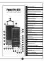
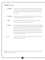
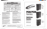
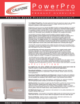
PowerPro 916
Portable
Public Address
Systems
Owner’s
Manual
PA916 Public Address Speaker
PA916-PS Powered Companion PA
PA916-SP Passive Companion Speaker
Power Pro 916 Owner’s Manual
Thank you for purchasing this PowerPro PA, the most versatile and appropriate portable PA for use in school, business, house of
worship and government facilities.
I invite you to register your product online for warranty coverage at our website: www.califone.com — while you’re there —
make sure to visit our complete line of multimedia players and recorders, wired and wireless headphones and headsets,
computer peripherals and other Califone products.
While online, make sure you register your PowerPro for its limited six year warranty.
Sincerely,
Contents
a) PowerPro Public Address System
b) Power Cord
c) Operation Manual
d) RC-300 Remote Control With 2 AAA Alkaline Batteries
e) 6-Year Warranty & Registration Card
f ) Project Intercept Card
Roscoe Anthony
President, Califone® International, Inc.
Unpacking
Check carefully for damage which may have taken place
during transit. Report any damage claim directly to the
freight carrier immediately. Save product(s) and packaging
for inspection by the carrier’s claim agent. Notify your
dealer of the pending claim.
Also included may be one or more of the
following optional items:
• Q-316 Handheld 16-Channel Wireless UHF Microphone
with 2 AA alkaline batteries.
Warranty Registration
• M-316 Beltpack Transmitter with 2 AA alkaline batteries.
Please register for your 6-year warranty online
at www.califone.com to activate.
• LM-316 Lapel Microphone for the M-316
• CM-316 Flexible Collar Microphone for the M-316
Service Repairs
• HBM-316 Headband Microphone for the M-316
Should your unit require repair contact the dealer
or Califone Service Department at: (800) 722-0500
to obtain a Return Authorization number. After
receiving the RA, ship the unit to Califone prepaid.
Collect shipments will be refused.
• PADM-558 High Quality Handheld Wired Microphone
with cable and XLR Connector. (or other Califone
cabled microphone.)
1
1
Telescoping Handle
2
Two 16-channel UHF wireless mic receivers
3
Compact Disc Player
4
Variable Speed Cassette Recorder/Player
5
Microphone Volume (2)
6
Speech/Music Switch (2)
7
XLR & 1/4” Microphone Inputs(2)
8
Audio Line Out Volume
9
Audio Line Out XLR (2)
10
CD-Tape On/Off & Volume
11
Line-In Volume Control
12
Line-In RCA Jacks
13
Line-Out RCA Jacks
3
14
Treble Control
4
15
Bass Control
16
Digital Master Volume
17
16-channel UHF Transmitter
18
5 Ampere Fuse
19
A/C Power Socket
15
20
Battery Low/Charge Indicators
16
21
Green Power On Indicator
22
Power On/Off Switch
23
Voice Priority (Ducking) Switch
24
1/4” Phone Jack Speaker Out
13
25
1/4” Phone Jack Speaker Out Switched
27
26
Speaker Mute Switch
27
Beefy 3.5” Integral Wheels
28
LED Lights for Power, RF, Audio
Power Pro 916
SPECIFICATIONS
1
2
28
8
5
10
6
14
7
9
11
12
17 18
19
20 21
22 23
24 25 26
2
Operation
Battery
Charge the battery for at least 10 hours before using the PA916 or PA916-PS. Simply plug the power cord into an AC
outlet and charging begins automatically. The charging indicator will flash until fully charged, then it will stay green. The
unit can be used while it is plugged in for charging.
There are two indicators above the main power switch. When the unit is turned on, the one on the left will light “red”
when the battery has a low charge. The one on the right will glow “green” if the battery is fully charged or if operating
on A/C power.
It is recommended that the battery be recharged after several hours of usage, rather than stored with a low battery. This
will prolong battery life. Storing more than 30 days without recharging will deteriorate the battery.
Digital Master Volume Control
When the main power switch is turned on, the Digital Master Volume Control is at the lowest level to prevent accidental
damage to the amplifier or internal speakers. The volume can be controlled in two ways; using the “Up” “Down” buttons
on the mixer panel or using the RC-300 infrared remote control. The remote sensor must be used in front of the speaker
as the sensor is behind the speaker grille.
Recommended Set-up Procedure
Ideally the master volume should be at maximum volume before the wireless receiver and microphone volumes
are adjusted to the desired loudness. Since there are always at least two (2) volume controls to contend with, it is
suggested that prior to turning the power on the UHF receiver volume controls be set at “10 o’clock”. Also set the
microphone volume controls at “10 o’clock”. Turn on the main power switch and use either a wireless microphone
or cabled microphone to adjust the master volume.
Tape & CD
The main power switch does not control the CD and Tape recorder. A separate power switch is combined with the
Tape/CD volume control to limit battery drain when the Tape or CD are not being used.
Wireless Receivers
There are two (2) independent combination XLR/1/4” jacks for using microphones with cables. Each jack has a volume
control which effects the loudness of both wired and wireless microphones. Also each has a “Voice/Music” switch. On
“music” program the sound is full fidelity, while on “voice” the sound is tailored to give maximum projection while limiting battery drain.
3
Operation continued
Line In
Insert both RCA plugs into the RCA jacks when using a stereo input. The left and right channels are combined so no program material is lost. If the source is monaural, either RCA jack can be used. The Line In volume control is used to increase
or decrease the level of the input signal.
Line Out
The two RCA jacks are used to connect to the input of another piece of equipment such as a tape recorder, mixer or
another amplified speaker. The outputs are monaural and volume level will depend on the volume of the source. For
example, the tape or CD player level is controlled by the tape/CD volume control. Lie out is independent of the Master
Volume Control.
Tone Controls
The separate base and treble controls provide a wide range of adjustment for increasing or decreasing either the bass or
treble from “flat” frequency response. The center or “12 o’clock” position is flat.
Speaker Mute Switch
Engaging this switch will cut off the sound of all speakers, internal and external, except as explained in the section under
“PA916-PS operation”.
Voice Priority
This feature is used for voice override of the music program when using a microphone. The “ducking” circuit attenuates
the music when a person speaks into the microphone. After a 3 second delay in the speech, the music returns to the
previous level.
4
Wireless Operation
Feedback is a shrill screeching sound produced by the speaker system when a microphone is being used too close to the
front of the speaker. The microphone picks up the sound of the speaker system and it becomes reamplified. It is a selfsustaining loop which can damage the system if allowed to continue, not to mention the annoyance caused to persons
nearby. Always stand 4 to 6 feet from the speaker to minimize the opportunity for feedback from the speaker system.
Wireless UHF Receivers
Wireless receiver “A” is preset at the factory for channel 4 and
receiver “B” is set on channel 6. There are three (3) LEDs on the
receiver; power (green), RF reception (red) and Audio reception
(amber).
UHF FULL DIVERSITY
There are also LEDs on the front of the speaker above the grille
making it easy to see if the microphone and receiver are working properly. A red LED indicates RF (radio frequency) from the
microphone, while an amber LED indicates audio.
Wireless Transmitter
The PowerPro PA916 incorporates a 16 channel UHF transmitter with its own power switch for wireless transmission to
the Powered Companion Speakers PA916-SP. The transmitter is preset at the factory to channel 13. It is recommended
that the user not randomly change this setting. If using the transmitter function change wireless receiver “A” from channel 1 to any other channel except channel 13 to prevent the transmitter from blocking the receiver.
Microphone Lockout
Two wireless microphones can be used at the same time, but separate channels (frequencies) must be used. For instance,
if using receiver “A” on channel 4, two microphone beltpack transmitters cannot be used at the same time. The first
transmitter turned on will dominate and lock out the other. The second microphone should be used with receiver “B” on
a different frequency which will allow two persons to talk at the same time.
Turn the transmitter power switch to OFF when not being used to minimize battery drain.
5
Microphones & Belt-Pack Transmitter
Q-316 Wireless Microphone
16-Channel UHF Transmitter
Power Low Battery LED
Battery Compartment
LM-316 Lapel Mic
Channel Selector Switch
M-316 Wireless Belt Pack Transmitter
Power On Switch
Microphone Jack
CM-316 Collar Mic
Power On/
Low Batt. LED
Volume Control
16-Channel
UHF Transmitter
Battery
Compartment
HBM-316 Headband Mic
6
Cassette Recorder/Player
Note: Remove the protective pad from behind the cassette door before inserting a cassette tape.
1
RECORD
Press this key together with either F. PLAY or R.PLAY to Record.
2
REWIND
Press this key to rewind the tape.
3
REVERSE PLAY
Press this key to Play the tape backwards.
4
STOP
Press this key to stop the tape.
5
FORWARD PLAY
Press this key to play the tape forward.
6
FAST FORWARD
Press this key for Fast Forward.
7
MODE
Press this key to select one of the following 3 modes.
1) The tape will play to the end in either direction and stop automatically.
2) The tape will play to the end in the forward mode, then reverse and play to the end of the other side of the tape in Record or Play
3) This mode provides continuous play operation in the Play function.
8
MODE LED INDICATORS
9
SPEED ADJUSTMENT
10
COUNTER
11
COUNTER RESET BUTTON
12
EJECT
12
11
10
9
Normal speed; center position. Turn
clockwise to increase the speed in
3% increments up to 15%. Turn counter
clockwise to reduce the speed in 3%
increments down to 15%.
The counter is a 3-digit LCD display.
Reset to “000” by pushing the button.
This button opens the cassette door.
8
7
1
2
7
3
4
5
6
Automatic Cassette Program Search System
The APSS (Automatic Program Search System) allows the user to skip the program being played
and move the tape in the Forward or in the Reverse direction to the next program or to the previous
program. It operates on the principal that there is a short period of silence between programs.
When the Tape Deck is in the Play mode and the “FF” is momentarily pressed and released within 0.5
sec, the tape advances rapidly until the next program ahead is reached. At this point, the tape stops
momentarily and playback of the next program starts.
When the Tape Deck is in the Play mode and the “FR” is momentarily pressed and released within 0.5
sec, the tape rewinds rapidly until the beginning of the previous program is reached. At this point
the tape stops momentarily and playback of the previous program starts.
CD Player
1
CD SLOT
2
LCD DISPLAY
3
PAUSE/PLAY
After the power is turned on the LCD display will read “NO disc” Gently push the CD into the slot and
the CD will be recognized and begin playing track #1.
When “Play” is pressed, the first track will begin to Play. When Play is pressed again, the mode goes to
Pause. When pressed a third time the mode returns to Play.
1
2
9
8
4
3
7
10
6
5
NO dISC
When STOP is pressed from Play or Pause the program is advanced to the end of the last track on the CD.
4
STOP
5
SKIP FORWARD When FWD is pressed from the Stop mode, the program will advance to the first track. When pressed
from Play or Pause mode, the program will advance one track. Continuing to press FWD will advance
one track each time.
8
CD PLAYER Continued
6
SKIP/REVERSE
When REV is pressed from the Stop mode, the program will go back one track and begin playing
the last track on the CD. When pressed from Play or Pause mode, the program will go back to the
beginning of the track which was already playing. Continuing to press REV will step back one
track at a time.
7
REPEAT/ENTER
Pressing Repeat once will continuously replay the selected track. Pressing it twice will replay all
tracks continuously. Pressing Repeat a third time will clear the settings.
8
SHUFFLE
Pressing Shuffle from Stop, Play or Pause will result in random selection of tracks and begin
playing continuously. Pressing Shuffle again will clear the program.
9
PROGRAM
In Stop mode, press Program and observe “P 1: ” on the LCD. Press FWD and see “1:01”, press FWD
again and see “1 :02”. Press enter and “2” will appear in the upper right of the LCD. Press FWD three
more times and see “1:05”. Press Enter and see “5” added to the LCD. Press play and the second track
will play, then advance to track 5. After playing all the selected tracks the program advances to the
end of the CD. Pressing Play will repeat the program. To clear the program in the Stop mode, just
press Program. Individual selections can be cleared while they are playing by pressing Program.
This will not affect other selected tracks.
10
EJECT
Pressing Eject from any mode will advance the program to the last track on the CD and eject the
CD. “NO dISC” will appear on the LCD.
NOTE: The CD player is capable of playing CD, CD-R and CD-RW discs, however due to the condition of the disc or the original it
was copied from some discs may not play.
9
Powered Companion Speaker PA916-PS
The Powered Companion PA has the same amplifier, power supply and speaker compliment as the full featured PowerPro PA916. It
does not have the mixer panel because it can be controlled by the PowerPro PA916.
With the integral 16-channel selectable wireless UHF receiver, it can function as a stand alone PA speaker when using a Q-316
Handheld microphone or the M-316 Beltpack transmitter with a LM-316, CM-316 or HBM-316 microphone. Although there are 5
LEDs on the front of the PA916-PS only 3 lights function on this unit because there is only one receiver. The red LED indicates RF,
the amber LED is for audio, and the green LED indicates power On.
Full Wireless Operation
As the transmitter on the PA-16 is preset on channel 13, the receiver of the PA916-PS is also set on 13. Any audio from the PA916
can be transmitted to the PA916-PS without wiring. There is no limit on the number of PA916-SP speakers that can be used with the
PA-916 within a range of 300 feet.
Audio Line Buss
When linking one or two PA916-PSs to the PowerPro PA916 via audio line, the PSC-50 XLR cable is connected to Audio Line Out XLR
connector on the PA916. The other end is connected to Line In XLR on the Powered Companion Speaker.
The Master Volume Control on the Audio Line panel of the master will adjust the PowerPro PA916 as well as all the Powered or Passive Companion Speakers, however the loudness needs to be adjusted via the Master Volume Control on the PA916-PS as well.
Note: The mute switch on the PA916 will silence all speakers connected to it by cable. However in the full wireless mode using the
transmitter of the PowerPro the mute will have no effect.
10
Power Pro 916-P
1
3
4
2
5
7
6
8
15
9
10
11
12
13
14
16
1
Telescoping Handle
2
16-channel UHF wireless mic receivers
3
Audio Line Out XLR
4
Treble Control
5
Bass Control
6
Digital Master Volume
7
Dual Steel Skid Guards
8
A/C Power Socket
9
Battery Low/Charge Indicators
10
Green Power On Indicator
11
Power On/Off Switch
12
Voice Priority (Ducking) Switch
13
1/4” Phone Jack Speaker Out
14
1/4” Phone Jack Speaker Out Switched
15
Speaker Mute Switch
16
Integral Wheels
Power Pro 916-SP
1
2
3
11
1
Telescoping Handle
2
1/4” Phone Jack Speaker In
3
Integral Wheels
Passive Speaker System PA916-PS Operation
The PA916-SP is connected to one of two outputs from the PowerPro PA916 or Powered Companion Speaker via SP-50 Cable with
1/4” phone plugs.
Connecting to the “Speaker Out” jack will divide the power between the PowerPro PA916 or PA916-PS and PA916-SP. Connecting to
the “Switched Out” will disconnect the internal speakers of the PA916 and deliver all of the power to the PA916-SP.
NOTE: There are five (5) LEDs on the front of the speaker, however they are disconnected because there is no internal amplifier or
wireless receiver in this passive system.
Mechanical Notations
Telescoping Handle and Wheels
These are only intended for pulling the PowerPro over relatively smooth surfaces. Using the handle to lift or carry the unit or pulling up stairs will cause damage not covered by the warranty.
Tripod Mount
A recess is incorporated on the bottom of all PowerPro Speakers for mounting to the TP-50 tripod.
12
Specifications
Acoustic Speaker Compliment
Woofer
Tweeter
Frequency Response
Amplifier
Sound Pressure Level
Power Sources
10” Diameter, 40 Oz. Magnet, 2” Dia. Voice Coil, 6 Ohm
Compression Horn Driver, 12 Oz. Magnet, 1” Voice Coil, 8 Ohm
45Hz to 18KHz
90 Watts RMS @ 5% THD (AC)
94 dB, 1 Watt @ 1 Meter
100-240 volt AC switchmode power supply and 12 volt 7 AH
maintenance-free lead acid batteries (2)
Wireless System
Receiver: Two 16-channel selectable UHF diversity wireless receivers 798-805 MHz.
Antennas are hidden internally.
Microphone Transmitters
Handheld wireless microphone or beltpack transmitters optional. Powered by 2 ea. 1.5 volt AA batteries (included). Beltpack transmitter used with choice of hands-free headset, collar or lapel microphones.
CD Player
Built-in anti-shock mechanism. Fully programmable. Shuffle feature. Plays CD, CD-R/RW.
Tape Cassette
Full logic player and recorder. Automatic program search feature. 4-digit LCD tape counter. Variable speed. Auto reverse.
Transmitter to Powered Companion Speaker
16-Channel selectable UHF transmitter for wireless transmission from PA916 to multiple PA916-SP speakers. 300 ft. range.
Audio Line
Line level XLR jacks (2) providing for attaching PA916-SP speakers via cable. Features volume control for remote speaker(s).
Mixer Panel
Mixer panel accepts two wired microphones via high quality combination connectors for both XLR and 1/4” phone plugs. Voice
music switch adds emphasis in the voice range for longer range projection. Line-In via dual RCA jacks with volume control.
Line-Out via dual RCA jacks. Separate Bass and Treble tone controls. Voice priority switch activates “ducking circuit” which overrides music programs when microphone is used. Speaker mute switch mutes the main speaker plus all other speakers connected.
Speaker out. Both switched and unswitched 1/4” phone jacks for connecting speakers.
Dimensions
Weight
Compliance
26 H x 12” W x 10” D
52 lbs.
FCC, CE, C-UL
13
CAUTION
RISK OF ELECTRIC SHOCK - DO NOT OPEN
!
CAUTION: TO REDUCE THE RISK OF ELECTRIC SHOCK, DO NOT REMOVE COVER OR BACK.
NO USER SERVICEABLE PARTS INSIDE. REFER SERVICING TO QAULIFIED PERSONNEL.
The lightening flash with arrowhead
within a triangle is intended to tell
the user that parts inside the product
are a risk of electric shock to persons.
This product is not designed to
function normally in strong electromagnetic fields. Consequently, the
audio quality may degrade while
the product is exposed to strong electromagnetic
fields. Normal audio quality operation will be
recovered when the strong electromagnetic field
is no longer present.
!
The exclamation point within a
triangle is intended to tell the user
that important operating and servicing
instructions are in the papers with
the appliance.
WARNING:
TO REDUCE THE RISK OF
FIRE OR ELECTRIC SHOCK, SO
NOT EXPOSE THIS APPLIANCE
TO RAIN OR MOISTURE.
Ce produit n’est pas conçu pour
un fonctionnement dans de forts
champs électromagnétiques. Par
conséquent, la qualité sonore peut
diminuer si ce produit est exposé
à un fort champ életromagnétique. La qualité
sonore redeviendra normale après affaib-lissement du champ électromagnétique.
IMPORTANT SAFETY INSTRUCTIONS
ATTENTION: ALL SAFETY AND OPERATING INSTRUCTIONS
SHOULD BE READ BEFORE OPERATING APPLIANCE. ALL OPERATING AND USE INSTRUCTIONS SHOULD BE FOLLOWED WHEN OPERATING THE APPLIANCE. HEED AND ADHERE
TO ALL WARNINGS ON THE APPLIANCE AND IN THE OPERATING
INSTRUCTIONS. RETAIN ALL SAFETY AND OPERATING INSTRUCTIONS FOR FUTURE REFERENCE.
WATER & MOISTURE - DO NOT USE THE APPLIANCE NEAR
WATER; IE. BATHTUB, WASHBOWL, KITCHEN SINK, LAUNDRY
TUB, WET BASEMENT OR SWIMMING POOL.
VENTILATION - DO NOT SITUATE THE APPLIANCE SO THAT
ITS LOCATION OR POSITION INTERFERES WITH ITS PROPER
VENTILATION. FOR EXAMPLE, THE APPLIANCE SHOULD NOT
BE SITUATED ON A BED, SOFA, RUG OR SIMILAR SURFACE THAT
MAY BLOCK THE VENTILATION OPENINGS. THE
APPLIANCE SHOULD NOT BE PLACED IN A BUILT-IN
INSTALLATION, SUCH AS A BOOKCASE OR CABINET, THAT
MAY IMPEDE THE FLOW OF AIR THROUGH THE VENTILATION
OPENINGS.
HEAT - SITUATE THE APPLIANCE AWAY FROM HEAT SOURCES
SUCH AS RADIATORS, HEAT REGISTERS, STOVES OR OTHER APPLIANCES (INCLUDING AMPLIFIERS) THAT PRODUCE HEAT.
POWER SOURCES - CONNECT THE APPLIANCE ONLY TO A
POWER SUPPLY TYPE DESCRIBED IN THE OPERATING INSTR-UCTIONS OR MARKED ON THE APPLIANCE.
GROUNDING OR POLARIZATION - PRECAUTIONS SHOULD BE
TAKEN SO THAT THE GROUNDING OR POLARIZATION MEANS OF
THE APPLIANCE ARE NOT DEFEATED.
POWER CORD PROTECTION - POWER SUPPLY CORDS
SHOULD BE ROUTED SO THAT THEY ARE NOT LIKELY TO BE
WALKED ON OR PINCHED BY ITEMS PLACED UPON OR AGAINST
THEM, PAYING PARTICULAR ATTENTION TO CORDS
AT PLUGS, CONVENIENCE RECEPTACLES, AND THE POINT WHERE
THEY EXIT FROM THE APPLIANCE.
CLEANING - THE APPLIANCE SHOULD BE CLEANED ONLY AS RECOMMENDED BY THE MANUFACTURER.
NON USE PERIODS - UNPLUG THE APPLIANCE POWER CORD
FROM THE OUTLET WHEN LEFT UNUSED FOR A LONG PERIOD OF
TIME.
OBJECT & LIQUID ENTRY - CARE SHOULD BE TAKEN SO THAT
OBJECTS DO NOT FALL AND LIQUIDS ARE NOT SPILLED INTO THE
ENCLOSURE THROUGH OPENINGS.
DAMAGE REQUIRING SERVICE - THE APPLIANCE SHOULD BE SERVICED BY QUALIFIED SERVICE PERSONNEL WHEN: (A) THE POWER
SUPPLY CORD OR THE PLUG HAS BEEN DAMAGED (B) OBJECTS
HAVE FALLEN OR LIQUID HAS BEEN SPILLED INTO THE APPLIANCE
(C) THE APPLIANCE HAS BEEN EXPOSED TO RAIN (D) THE APPLIANCE DOES NOT APPEAR TO BE OPERATING NORMALLY OR EXHIBITS A MARKED CHANGE IN PERFORMANCE (E) THE APPLIANCE HAS
BEEN DROPPED OR THE ENCLOSURE DAMAGED.
SERVICING - THE USER SHOULD NOT ATTEMPT TO
SERVICE THE APPLIANCE BEYOND THAT DESCRIBED IN
THE OPERATING INSTRUCTIONS. ALL OTHER SERVICING REFER TO
A QUALIFIED SERVICE PERSONNEL.
14
Califone® International Inc. • 1145 Arroyo Avenue, # A • San Fernando, CA 91340 USA
Toll Free 800.722.0500 | Toll Free Fax 877.402.2248
International Customers call 818.407.2400 or Fax 818.407.2405 califone.com