1
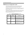
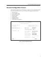
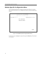
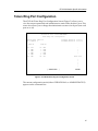
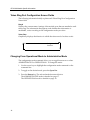
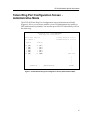
SmartSwitch 9000
9T122-08
Local Management Appendix
9031653-03
Appendix
9T122-08 Module Specific
Information
Introduction
This appendix contains local management information that is speciÞc to the
9T122-08 Token Ring MicroLAN Switch Extension Module.
Module Interfaces
The 9T122-08 Token Ring MicroLAN Switch Extension Module has Þve interfaces.
Table 1 lists the identifying number, name, and description of each interface.
Table 1. 9T122-08 Token Ring MicroLAN Switch Module Interfaces
System
Interface
Number
Bridge
Interface
Number
Interface
Name
Interface
Description
1
SMB-1
1 Mbps System Management Bus
2
SMB-10
10 Mbps System Management Bus
3
1
FNB
Flexible Network Bus (FDDI)
4
2
TOKEN RING 1
Token Ring 1 Front Panel Interface
5
3
TOKEN RING 2
Token Ring 2 Front Panel Interface
1
9T122-08 Module Specific Information
FNB Resource Configuration Codes
The 9T122-08 Token Ring MicroLAN Switch Extension Module provides
connectivity between one of three interfaces: the front panel Token Ring
interface(s) and the FDDI rings on the backplane (FNB-1 or FNB-2).
The FNB Resource ConÞguration Screen allows you to connect the moduleÕs front
panel Token Ring interfaces to one of the chassisÕ two FDDI networks (FNB-1 or
FNB-2) via a bridge/switch.
The FNB Resource ConÞguration Screen lists all the possible connections that the
speciÞed module can support on the FNB, displays the current connection, and
allows you to change the connection. Table 2 lists and describes the FDDI
Connections from which you can select.
Table 2. 9T122-08 Token Ring MicroLAN Switch Module FNB
Resource Configuration Codes
2
ConÞguration
ID
FDDI
Connections
Description
1
NORING <-> TRNG
Neither the FNB-1 nor the FNB-2 on
the chassisÕ backplane is connected to
the moduleÕs bridge/switch.
2
FNB1 <-> TRNG
3
FNB2 <-> TRNG
The FNB-1 on the chassisÕ backplane
and the moduleÕs front panel Token
Ring interfaces are connected to the
same bridge/switch.
The FNB-2 on the chassisÕ backplane
and the moduleÕs front panel Token
Ring interfaces are connected to the
same bridge/switch.
9T122-08 Module Specific Information
General Configuration Screen
The General ConÞguration Screen (Figure 1), displays various information about
the selected module and allows you to set the following general parameters:
¥
¥
¥
¥
¥
¥
¥
¥
Date and Time
Screen Update Time
Screen Lockout Time
Host IP Address
Subnet Mask
Default Gateway
Default Interface
TFTP Gateway IP Address
SmartSwitch 9000
LOCAL MANAGEMENT
General Configuration
Module Name: 9T122-08
Slot Number: 2
Module Serial #: 04
Module Board Revision:
FLASH Memory:
Firmware Revision: 01.08.07
BOOTPROM Revision: 01.01.09
04
Module
Module
Screen
Screen
Date:
05/24/1996
Time:
09:18:13
Refresh Time:
03 sec
Lockout Time:
15 min
2 MB
Host IP Address:
Subnet Mask:
XXX.XXX.XXX.XXX
255.255.0.0
Default Gateway:
Default Interface:
NONE DEFINED
NONE DEFINED
Base MAC Address:
00-00-1D-01-03-04
TFTP Gateway IP:
0.0.0.0
SAVE
RETURN
Figure 1. General Configuration Screen
3
9T122-08 Module Specific Information
General Configuration Screen Fields
The following information brießy explains each General ConÞguration Screen
Þeld.
Module Serial #
Displays the serial number of the selected module.
Module Board Revision
Displays the version number of the selected module.
FLASH Memory
Displays the amount (megabytes) of ßash memory in the selected module.
Module Date
Contains a value that the module recognizes as the current date. To enter a new
date, highlight the Þeld and enter the date in MM/DD/YYYY format. The month
and day portion of the date must include two digits. Therefore, enter a leading
zero for months January through September, and for dates less than 10. For
example, for June 4, 1996, enter 06/04/1996 (slashes are optional). If you do not
enter slashes to separate the month, day, and year values, the Þrst eight digits you
enter in this Þeld represent an entry (i.e., 06041996).
Module Time
Contains a value that the module recognizes as the current time. To enter a new
time, highlight the Þeld and enter the time in HH:MM:SS format. Notice that
there is no AM/PM indicator. Time should be entered based upon a 24 hour clock.
For 4:07 p.m., enter 16:07:00 (colons are optional). If you do not enter colons to
separate the hours, minutes, and seconds values, the Þrst six digits you enter in
this Þeld represent an entry (i.e., 160700). For 6:12 a.m., enter 6:12:00 or 061200.
NOTE
The moduleÕs default date and time settings are indeterminate. The internal
calendar and clock begin running as soon as you install the module.
Screen Refresh Time
Contains the rate at which the moduleÕs screens are updated. This setting
determines how frequently (in seconds) information is updated on the screen. To
enter a new refresh rate, highlight the Þeld and enter a number. The default
refresh rate is 3 seconds. The range is 3 - 99 seconds.
4
9T122-08 Module Specific Information
Screen Lockout Time
Contains the maximum number of minutes that the Local Management
application will display a moduleÕs screen while pending input or action from a
user. For example, if you enter 5 in this Þeld, users will have up to Þve minutes to
respond in some fashion to each of the speciÞed moduleÕs Local Management
screens. In our example, after Þve minutes of ÒidlenessÓ (no input or action), the
Local Management application terminates the session on the selected module and
the Slot Selection Screen reappears. To enter a new lockout time, highlight the
Þeld and enter a number. The default lockout time is 15 minutes. The range is 1 30 minutes.
Host IP Address
Contains the Internet Protocol address currently assigned to the selected module.
Set this Þeld according to your network requirements. Highlight the Host IP
Address Þeld and enter the desired IP address using dotted decimal notation (4
decimal values between 1 and 255 separated by periods) as follows:
255.255.255.255
(255 is the maximum number that you can enter in any of the four segments.
Default = 0.0.0.0 .) This address can be used by any of the system interfaces on the
module.
Subnet Mask
Contains the subnet mask for the selected module. A subnet mask Òmasks outÓ
the network bits of the IP address by setting the bits in the mask to 1 when the
network treats the corresponding bits in the IP address as part of the network or
subnetwork address, or to 0 if the corresponding bit identiÞes the host. The
default subnet mask uses the Þrst two portions of the IP address to identify the
network id, leaving the rest of the IP address to identify speciÞc nodes. To enter a
new subnet mask, highlight the Þeld and enter a new value using dotted decimal
notation (4 decimal values between 1 and 255 separated by periods) as follows:
255.255.255.255
(The Subnet Mask Þeld defaults to the natural mask value, based on the IP
Address that you entered for the device.)
Default Gateway
Contains the IP Address of the device to which all packets addressed to an
unknown network or host are sent. If you do not conÞgure a Default Gateway,
any packets that are addressed to an unknown network or host will be dropped.
This Þeld is not deÞned until you enter an appropriate value using dotted
decimal notation (4 decimal values between 1 and 255 separated by periods).
5
9T122-08 Module Specific Information
Default Interface (Toggle)
Contains the number that represents the interface that is connected to the
moduleÕs Default Gateway. In some instances, dissimilar modules have different
corresponding interface numbers. For example, if you are assigning a default
interface to a 9T122-08 module and you enter a 3, then the default interface is the
Flexible Network Bus. However, if you are assigning a default interface to a
9F310-02 module and you enter a 3, then the default interface is the Internal
Network Bus. See Table 1 for module-speciÞc interface information. The default
is NONE, meaning no default interface selected.
NOTE
The Default Interface Þeld becomes active after you enter an IP address in the
Default Gateway Þeld.
Base MAC Address
Displays the MAC Address of the selected module. This is the MAC Address of
the SMB-10 interface.
TFTP Gateway IP
The IP address of the router that connects to or is closest to the module. ConÞgure
this address when you are performing TFTP downloads in a routed environment
(if proxy ARP is disabled on the router).
6
9T122-08 Module Specific Information
Token Ring Bridge Configuration (Screen 1)
The 9T122-08 Token Ring Bridge ConÞguration Screen 1 (Figure 2), provides basic
setup options for making a bridge operational in your network.
SmartSwitch 9000
LOCAL MANAGEMENT
Bridge Configuration
Module Name: 9T122-08
Slot Number: 2
Firmware Revision: 01.08.07
BOOTPROM Revision: 01.01.09
Bridge Address: 00-00-1D-01-03-04
Bridging Interfaces: 3
Bridge Number
(hex):
1
Bridge Priority Label (hex):
8000
Bridge Path Cost
(hex): 0000000A
Type of STA:
Novell Xlat:
Interface #
1 (FNB)
2 (TR1)
3 (TR2)
SAVE
[IEEE]
[NONE]
MAC/Local Address
Bridge State
Status
00-00-B8-80-C0-A0
00-00-B8-80-C0-60
00-00-B8-80-C0-E0
forwarding
forwarding
forwarding
[ENABLED]
[ENABLED]
[ENABLED]
INTERFACE CONFIGURATION
RETURN
Figure 2. 9T122-08 Token Ring Bridge Configuration Screen 1
NOTE
To modify a non-toggle Þeld on this screen, use the arrow keys to highlight the
Þeld, then press the Enter key. Now you can modify the Þeld.
7
9T122-08 Module Specific Information
Bridge Configuration Screen Fields (Screen 1)
The following information brießy explains each Bridge ConÞguration Screen 1
Þeld.
Bridge Address
Displays the MAC Address of the bridge.
Bridging Interfaces
Displays the total number of bridging interfaces on the selected module.
Bridge Number
Allows you to enter a hexadecimal number that uniquely identiÞes a bridge when
more than one bridge is used to span the same two segments. Valid bridge
numbers range from 01 to 0F (15).
Type of STA (Toggle)
Allows you to set the method that bridges use to decide which bridge is the
controlling (Root) bridge when two or more bridges exist in parallel (Spanning
Tree Algorithm). Valid entries include IEEE and None. Press the Space Bar to
toggle to the desired value.
!
CAUTION
All bridges in a network must use the same Spanning Tree protocol. The IEEE
protocol has a unique format for its Bridge Protocol Data Units (BPDU). Trying
to mix STA protocols results in an unstable network.
Bridge Priority Label
Allows you to enter a hexadecimal number that identiÞes the write-able portion
of the Bridge ID, i.e. the Þrst two octets of the Bridge ID. Valid bridge priority
labels range from 0000 to FFFF.
Novell Xlat (Toggle)
Novell translation, which converts MAC addresses in most signiÞcant bit (MSB)
format to least signiÞcant bit (LSB). Valid choices are:
8
¥
NONE (default) - No translation performed for Novell IPX/SPX packets.
¥
DLC - Translation performed within the data link control layer for Novell
IPX/SPX packets (provides MSB-to-LSB MAC address conversion).
¥
LLC - Translation performed within the Logical Link Control layer for Novell
IPX/SPX packets (provides MSB-to-LSB conversion compatible with the 9T122
method).
9T122-08 Module Specific Information
Bridge Path Cost
Allows you to enter (as a hexadecimal number) the cost of the path to the root as
seen from the speciÞed bridge. Valid bridge path costs range from 00000001 to
0FFFFFFF.
Interface Number
Lists each bridge interface on the selected module; FNB, TR1, and TR2.
MAC/Local Address
Lists the hardware address of each listed bridge interface.
Bridge State
Displays the current state of each listed interface. The possible interface states
include:
Disabling:
Management has disabled this interface. No trafÞc can be received
or forwarded while the interface is disabled.
Learning:
The bridge is learning this interfaceÕs network addresses. The
bridge enters the learning state when the Transparent Database is
created (during start-up or after being deleted), or when the
Spanning Tree Algorithm detects a network topology change.
Listening:
The bridge is not adding information to the Transparent Database.
The bridge is monitoring BPDU trafÞc while preparing to move
from the learning to the forwarding state.
Forwarding:
The bridge is on-line and this interface is forwarding trafÞc.
Blocking:
This interface will not forward any trafÞc through the bridge.
Status (Toggle)
Allows you to set the bridge forwarding status of the listed interface (either
ENABLED or DISABLED). Press the Space Bar to toggle to the desired value.
Displaying Bridge Configuration Screen 2
To display Bridge ConÞguration Screen 2, use the arrow keys to highlight
INTERFACE CONFIGURATION, then press the Return key.
9
9T122-08 Module Specific Information
Token Ring Bridge Configuration (Screen 2)
The 9T122-08 Token Ring Bridge ConÞguration Screen 2 (Figure 3), provides basic
setup options for making a bridge operational in your network.
SmartSwitch 9000
LOCAL MANAGEMENT
Bridge Configuration
Module Name: 9T122-08
Slot Number: 2
Firmware Revision: 01.08.07
BOOTPROM Revision: 01.01.09
Bridge Address: 00-00-1D-01-03-04
Bridging Interfaces: 3
Bridge Number
(hex):
1
Bridge Priority Label (hex):
8000
Bridge Path Cost
(hex): 0000000A
Type of STA:
Novell Xlat:
Interface #
Ring
Speed
Ring
Number
Hop
Count
1 (FNB)
2 (TR1)
3 (TR2)
100
[16]
[16]
041
048
049
7
7
SAVE
STE
Forwarding
Bridge
Method
TP
[SRT]
[SRT]
[IEEE]
[NONE]
Unknown&Broadcast
Forwarding
TP
[STE]
[STE]
RETURN
Figure 3. 9T122-08 Token Ring Bridge Configuration Screen 2
10
9T122-08 Module Specific Information
Bridge Configuration Screen Fields (Screen 2)
The following information brießy explains each Bridge ConÞguration Screen 2
Þeld.
Ring Speed (Toggle)
Allows you to set each token ring interfaceÕs operating speed (either 4 Mbps or 16
Mbps). Press the Space Bar to toggle to the desired value.
Ring Number
Allows you to set the hexadecimal number that uniquely identiÞes the ring to
which the speciÞed interface is connected. Valid ring numbers range from 001 to
FFF.
Hop Count
Allows you to set the maximum number (1 through 7) of routing descriptors
allowed to be forwarded in All Routes or Spanning Tree Explorer frames.
STE Forwarding (Toggle)
Allows you to manually conÞgure whether a Spanning Tree Explorer frame is
forwarded or blocked. Press the Space Bar to toggle to the desired value (either
ENABLE or DISABLE). This is available only with the Spanning Tree Algorithm
(STA) set to NONE.
Bridge Method (Toggle - Available on Token Ring interfaces only)
Displays one of the following bridge methods:
¥
Source Route (SR) - All frames from the FNB are forwarded on the front panel
Token Rings with a source route RIF. There is no transparent frame support.
The Token Ring interface may only receive and transmit SR frames in this
mode. All TP frames are Þltered when they are received by the Token Ring
interface.
¥
Source Route Transparent (SRT) - Performs source route bridging when
required, transparent bridging when required, and translational bridging. The
Token Ring interface can receive and transmit both SR and TP frames.
¥
Transparent (TP) - There is no source routing support. The bridge performs
transparent 802.1d bridging. All SR frames are Þltered when they are received.
11
9T122-08 Module Specific Information
Unknown&Broadcast Forwarding
DeÞnes how frames destined for unknown destination addresses (not in the
bridge database) and broadcast destination addresses are handled when the
frame is transmitted by the Token Ring interfaces. This Þeld is per bridge
interface.
¥
For the FDDI interface, the frame cannot be changed. It is Þxed as a
transparent only (TP) network. Therefore, all unknown and broadcast frames
are sent onto FDDI as TP frames.
¥
For the Token Ring interfaces, this Þeld is selectable. Table 3 describes what
choices are available and when.
Table 3. Unknown and Broadcast Forwarding Choices
Bridge Method
TP
Unknown & Broadcast Forwarding Choices
TP - Frames that are destined for an unknown destination
address (not in bridge database) or a broadcast destination
address are forwarded on to the Token Ring(s) as TP frames.
No translation for source routing is performed.
ARE - Frames that are destined for an unknown destination
address (not in bridge database) or a broadcast destination
address are forwarded onto the Token Ring(s) as All Route
Explorer (ARE) frames. FDDI TP frames are translated to
this type of source routed frame.
SR
SRT (default)
12
STE - Frames that are destined for an unknown destination
address (not in bridge database) or a broadcast destination
address are forwarded onto the Token Ring(s) as Spanning
Tree Explorer (STE) frames. FDDI TP frames are translated
to this type of source routed frame.
ARE (See ARE deÞnition above)
STE (See STE deÞnition above). This is the default.
TP (See TP deÞnition above)
9T122-08 Module Specific Information
Saving Modifications
To save your modiÞcations of the values on the Bridge ConÞguration Screen:
1. Use the arrow keys to highlight SAVE at the bottom of the screen, then press
the Return key.
2. When the message ÒSAVED OKÓ appears, the edits you have made are saved.
If you exit without saving, the message ÒNOT SAVED -- PRESS SAVE TO
KEEP CHANGESÓ appears. If you exit without saving, your edits will be lost.
Exiting Bridge Configuration Screen 2
To exit Bridge ConÞguration Screen 2, use the arrow keys to highlight RETURN,
then press the Return key.
13
9T122-08 Module Specific Information
Module Specific Configuration Menu
The 9T122-08 Module SpeciÞc ConÞguration Menu Screen (Figure 4), contains
menu selections that allow you to conÞgure the moduleÕs ports and establish ring
security.
SmartSwitch 9000
LOCAL MANAGEMENT
Module Specific Configuration Menu
Module Name: 9T122-08
Slot Number: 2
Firmware Revision: 01.08.07
BOOTPROM Revision: 01.01.09
PORT CONFIGURATION
TOKEN RING SECURITY
RETURN
Figure 4. 9T122-08 Module Specific Configuration Menu Screen
Use the arrow keys to highlight an option, then press the Return key. The selected
screen appears.
14
9T122-08 Module Specific Information
Token Ring Port Configuration
The 9T122-08 Token Ring Port ConÞguration Screen (Figure 5), allows you to
view the current operational and administrative status of the moduleÕs ports. This
screen also allows you to change the administrative status of each port (turn each
port on or off).
SmartSwitch 9000 LOCAL MANAGEMENT
Token Ring Port Configuration
Module Name: 9T122-08
Slot Number: 2
RING #1
RO
1
2
3
4
RI
ACT
ENB
ENB
ENB
ENB
WRP
Firmware Revision: 01.08.07
BOOTPROM Revision: 01.01.09
RING #2
RO
1
2
3
4
RI
WRP
ENB
ENB
ENB
ENB
DIS
^
|
|
|
Token Flow
|
|
|
|
|
[ OPERATIONAL
]
RETURN
Figure 5. 9T122-08 Token Ring Port Configuration Screen
The current conÞguration mode (either OPERATIONAL or ADMINISTRATIVE)
appears on the command line.
15
9T122-08 Module Specific Information
Token Ring Port Configuration Screen Fields
The following information brießy explains each Token Ring Port ConÞguration
Screen Þeld.
Ring #
Displays the current status/settings of the module ports that are attached to each
token ring. The information that appears, and whether that information is
modiÞable, varies according to the conÞguration mode you select.
Token Flow
Graphically displays the direction in which the token travels. In other words:
RI
4
3
2
1
Bridge
Interface
RO
Changing From Operational Mode to Administrative Mode
The conÞguration mode command allows you to toggle between two values:
ADMINISTRATIVE or OPERATIONAL. To change the mode:
1. Use the arrow keys to highlight the conÞguration mode command on the
command line.
2. To toggle to the desired mode, press the Space Bar.
3. Press the Return key. The selected mode becomes effective.
The ADMINISTRATIVE mode is detailed on page 17.
The OPERATIONAL mode is detailed on page 19.
16
9T122-08 Module Specific Information
Token Ring Port Configuration Screen Administrative Mode
The 9T122-08 Token Ring Port ConÞguration Screen (Administrative Mode)
(Figure 6), allows you to turn a moduleÕs ports ON (administratively enable) or
OFF (administratively disable). You can turn ports ON/OFF individually or all on
the token ring.
SmartSwitch 9000 LOCAL MANAGEMENT
Token Ring Port Configuration
Module Name: 9T122-08
Slot Number: 2
RING #1
RO
1
2
3
4
RI
[ON
[ON
[ON
[ON
[ON
[ON
]
]
]
]
]
]
Firmware Revision: 01.08.07
BOOTPROM Revision: 01.01.09
RING #2
RO
1
2
3
4
RI
[ON ]
[ON ]
[ON ]
[ON ]
[ON ]
[OFF]
^
|
|
|
Token Flow
|
|
|
|
|
[ ENABLE ALL
]
[ADMINISTRATIVE]
RETURN
Figure 6. 9T122-08 Token Ring Port Configuration Screen (Administrative Mode)
17
9T122-08 Module Specific Information
Configuring (Administratively) an Individual Port
To administratively conÞgure an individual port:
1. Use the arrow keys to highlight the value in the Þeld of the port that you want
to conÞgure. Press the Space Bar until the desired value appears in the Þeld
(either ON or OFF).
2. Press the Return key.
Configuring (Administratively) All Ports
To administratively conÞgure all ports on the module, Token Ring 1 or Token
Ring 2:
1. Use the arrow keys to highlight the value in the enable/disable command
(lower left portion of the screen). Press the Space Bar until the desired value
appears in the Þeld (ENABLE ALL or DISABLE ALL, ENABLE TOKEN RING
1 or DISABLE TOKEN RING 1, ENABLE TOKEN RING 2 or DISABLE
TOKEN RING 2).
2. Press the Return key.
Exiting the Token Ring Port Configuration Screen
To exit the Token Ring Port ConÞguration Screen, use the arrow keys to highlight
RETURN, then press the Return key.
18
9T122-08 Module Specific Information
Token Ring Port Configuration Screen Operational Mode
The 9T122-08 Token Ring Port ConÞguration Screen (Operational Mode) (Figure
7), displays the current status of each port in the moduleÕs token ring. The status
value that appears in a portÕs Þeld is determined by the type of port (Lobe or
RI/RO), and its administrative status (On/Off).
SmartSwitch 9000 LOCAL MANAGEMENT
Token Ring Port Configuration
Module Name: 9T122-08
Slot Number: 2
RING #1
RO
1
2
3
4
RI
ACT
ENB
ENB
ENB
ENB
WRP
Firmware Revision: 01.08.07
BOOTPROM Revision: 01.01.09
RING #2
RO
1
2
3
4
RI
WRP
ENB
ENB
ENB
ENB
DIS
^
|
|
|
Token Flow
|
|
|
|
|
[ OPERATIONAL
]
RETURN
Figure 7. 9T122-08 Token Ring Port Configuration Screen (Operational Mode)
19
9T122-08 Module Specific Information
Table 4. Token Ring Port Operational Codes
If the port is a...
Ring Port
RI (ring-in) or
RO (ring-out)
And if the port is
administratively
turned...
Then, the operational status is:
ACT (Active)
The port is on and is passing data to the ring.
ON
WRP (Wrapped)
The port is on, but it is autowrapped, either because of a
cable failure or because the cable is not connected.
OFF
Lobe Port
DIS (Disabled)
The port is off (wrapped by Management).
INS (Inserted - phantom link is detected)
The lobe port is inserted into the ring.
ON
ENB (Enabled - no phantom link is present)
The lobe port is not inserted into the ring.
OFF
LNK (Linked - phantom link is detected)
The lobe port is trying to gain access to the ring, but it has
been prevented.
BYP (Bypassed -no phantom link is present)
The lobe port is not attempting to gain access to the ring.
ON or OFF
FLT (Speed Fault)
The ring speed of the port is in conßict with the ring speed
of the designated token ring. The port will remain
wrapped.
Exiting the Token Ring Port Configuration Screen
To exit the Token Ring Port ConÞguration Screen, use the arrow keys to highlight
RETURN, then press the Return key.
20
9T122-08 Module Specific Information
Token Ring Secured Station Configuration
The 9T122-08 Token Ring Secured Station ConÞguration Screen (Figure 8), allows
you to control access to the moduleÕs token ring network.
The Disabled mode (by default) allows all new stations to enter the ring.
When ring security is enabled in Alarm Only mode, the module stores the MAC
address of each station on the token ring network in a secure database or
Òallowed list.Ó The module can store up to 250 station MAC addresses on the
allowed list. The module retains the allowed list in its battery-backed NonVolatile Random Access Memory (NVRAM). When the module is powered up or
reset, all MAC addresses are retained and ring security is reenabled automatically.
The Alarm Only mode allows new stations to enter the ring, but a Òstation addedÓ
trap/alarm notiÞes the Network Management Station (NMS) of the event. The
trap/alarm includes the new stationÕs MAC address so that the network manager
can decide if the new station should be allowed on the ring.
!
CAUTION
Do not enter Remove/Alarm mode without Þrst entering the Alarm Only mode
or adding nodes to the allowed list. All nodes not appearing in the list, currently
active on the ring, WILL BE REMOVED!
The Remove/Alarm mode sends a ÒRemove Station MAC Frame CommandÓ to
new stations attempting to enter the ring, and a trap/alarm to the NMS informing
it of the action taken. If, after three attempts, the station (outside the hub) cannot
be removed from the ring, a trap/alarm is sent to the NMS informing it that Òthe
station could not be removed.Ó Also, the port is disabled for the station directly
connected to the hub and a trap/alarm is sent indicating port removal.
To access the 9T122-08 Token Ring Secured Station ConÞguration Screen from the
Module SpeciÞc ConÞguration Menu:
1. Use the arrow keys to highlight the Token Ring Security option.
2. Press the Enter key.
The 9T122-08 Token Ring Secured Station ConÞguration Screen (Figure 8),
appears.
21
9T122-08 Module Specific Information
SmartSwitch 9000 LOCAL MANAGEMENT
Token Ring Secured Station Configuration
Module Name: 9T122-08
Slot Number: 2
Firmware Revision: 01.08.07
BOOTPROM Revision: 01.01.09
Entry
Token Ring #1
Station Address
001
002
003
004
005
006
007
008
00-00-83-F2-7F-60
00-00-A6-30-19-61
00-00-A6-30-19-78
00-00-B8-28-08-C8
00-00-B8-80-C0-60
00-00-B8-DC-00-01
00-00-B8-F0-A0-D5
40-00-22-22-22-22
Stn Edit 00-00-00-00-00-00
ADD
[TOKEN RING 1]
Security Mode [ Alarm Only ]
[
9-16 ]
RETURN
Figure 8. 9T122-08 Token Ring Secured Station Configuration Screen
NOTE
22
Up to 8 station addresses appear on the screen. If additional station addresses
exist, a command containing the range of station addresses, such as [ 9-16 ],
appears on the command line (bottom of the screen). To view any additional
station addresses, highlight the range of station addresses command, then press
the Return key.
9T122-08 Module Specific Information
Token Ring Secured Station Configuration Screen Fields
The following information brießy explains each Token Ring Secured Station
ConÞguration Screen Þeld.
Station Address
Lists the MAC address of each station on the security ÒallowedÓ list. Up to 250
MAC addresses can appear in the list.
Stn Edit
Allows you to enter the MAC Addresses of stations that you want to add or delete
from the security ÒallowedÓ list.
Token Ring Security Configuration Screen Commands
Add/Delete (Toggle)
Allows you to manually add or delete stations from the security ÒallowedÓ list.
TIP
Before you add stations manually, see the Alarm Only security mode information
on the following page.
To manually add a station to the allowed list:
1. Use the arrow keys to highlight the Stn Edit Þeld, then press the Return key.
2. Enter the MAC Address of the station you want to add to the allowed list,
then press the Return key. You must enter the MAC Address in XX-XX-XXXX-XX-XX format.
3. If the Add/Del toggle command displays Add, then proceed to step 6.
Otherwise, use the arrow keys to highlight the letters Del in the Add/Del
command.
4. Press the Space Bar until the command toggles to display Add.
5. Press the Return key.
The station appears in the Station Address list. Ignore step 6.
6. Press the Return key.
The station appears in the Station Address list.
23
9T122-08 Module Specific Information
To manually delete a station from the allowed list:
1. Use the arrow keys to highlight the Stn Edit Þeld, then press the Return key.
2. Enter the MAC Address of the station you want to delete from the allowed
list, then press the Return key. You must enter the MAC Address in
XX-XX-XX-XX-XX-XX format.
3. If the Add/Del toggle command displays Del, then proceed to step 6.
Otherwise, use the arrow keys to highlight the word Add in the Add/Del
command.
4. Press the Space Bar until the command toggles to display Del.
5. Press the Return key. The station is removed from the Station Address list.
Ignore step 6.
6. Press the Return key.
The station is removed from the Station Address list.
Security Mode (Toggle)
Allows you to set one of three security modes for the moduleÕs token ring.
!
Make sure you understand the consequences of changing security modes.
CAUTION
Each mode offers more security than the previous mode. Select from the
following modes:
¥
Disabled - This is the default setting. Use this mode to temporarily disable ring
security so that new stations can enter the ring.
¥
Alarm Only - In this mode, new stations can enter the ring and are added to
the allowed list, but a ÒStation AddedÓ trap/alarm is sent to the Network
Management Station. This trap message is only sent once, and it includes the
new stationÕs MAC address so that the network manager can decide if the new
station should be allowed on the ring.
When temporarily disabling ring security to allow new users to enter the ring,
use the Alarm Only mode to reenable ring security. In Alarm Only mode, the
management module stores the MAC address of each station on the ring in
the allowed list. This eliminates entering MAC addresses one at a time using
the Stn Edit Þeld.
24
9T122-08 Module Specific Information
¥
NOTE
Remove/Alarm - This is the highest level of ring security. In this security mode,
the ring is locked to new stations. The Remove/Alarm mode sends a ÒRemove
MAC FrameÓ command to a new station attempting to enter the ring, and a
trap/alarm to the NMS informing it of the action taken. If, after three attempts,
the station cannot be removed from the ring, remove alarm sends a trap/alarm
ÒRemove FailureÓ to the NMS, informing it that the station could not be
removed.
If you change directly from Disabled mode to Remove/Alarm mode, all stations
that have not been added to the allowed list will be removed from the token ring.
Selecting a Security Mode
To select a Security Mode:
1. Use the arrow keys to highlight the Security Mode Þeld.
2. Press the Space Bar to toggle to the desired security mode (either Disabled,
Alarm Only, or Remove/Alarm).
3. Use the arrow keys to highlight the SAVE/EXECUTE command, then press
the Return key. The selected mode of ring security becomes effective.
Viewing Previous/Next Page of Station Addresses
To view the previous/next page (if there is one) of station addresses, use the
arrow keys to highlight the appropriate range of station addresses command (for
example, [ 9-16 ]), then press the Return key.
Exiting the Token Ring Secured Station Configuration Screen
To exit the Token Ring Secured Station ConÞguration Screen, use the arrow keys
to highlight RETURN, then press the Return key.
25
9T122-08 Module Specific Information
Bridge Statistics Screen
The 9T122-08 Bridge Statistics (TOTAL) Screen (Figure 9), displays the moduleÕs
transparent bridge and source route bridge statistics. The statistics are categorized
as follows:
¥
¥
¥
¥
Transparent Unicast
Transparent Broadcast
Source Route Unicast
Source Route Broadcast
SmartSwitch 9000 LOCAL MANAGEMENT
Bridge Statistics (TOTAL)
Module Name: 9T122-08
Slot Number: 2
Firmware Revision: 01.08.07
BOOTPROM Revision: 01.01.09
FDDI Interface :
Transparent Transparent Source Rte Source Rte
Unicast
Broadcast
Unicast
Broadcast
Frames Transmitted:
Frames Received:
Kbytes Transmitted:
Kbytes Received:
Frames Filtered:
[
TOTAL
]
[
0
0
0
0
0
FNB
0
0
0
0
0
]
[REFRESH
0
0
0
0
0
3sec]
Figure 9. 9T122-08 Bridge Statistics (TOTAL) Screen
26
Totals
RETURN
9T122-08 Module Specific Information
Bridge Statistics Screen Fields
The following information brießy explains each Bridge Statistics Screen Þeld.
Interface
IdentiÞes the interface type as either FDDI Interface, TOKEN RING Interface #1,
or TOKEN RING Interface #2.
Frames Transmitted
Displays the number of (transparent unicast, transparent broadcast, source route
unicast, and source route broadcast) frames transmitted by the interface, as well
as the total number of frames transmitted (sum of the four categories).
Frames Received
Displays the number of (transparent unicast, transparent broadcast, source route
unicast, and source route broadcast) frames received by the interface, as well as
the total number of frames received (sum of the four categories).
Kbytes Transmitted
Displays the number of (transparent unicast, transparent broadcast, source route
unicast, and source route broadcast) kilobytes transmitted by the interface, as well
as the total number of kilobytes transmitted (sum of the four categories).
Kbytes Received
Displays the number of (transparent unicast, transparent broadcast, source route
unicast, and source route broadcast) kilobytes received by the interface, as well as
the total number of kilobytes received (sum of the four categories).
Frames Filtered
Displays the number of (transparent unicast, transparent broadcast, source route
unicast, and source route broadcast) frames Þltered by the interface, as well as the
total number of frames Þltered (sum of the four categories)
Bridge Statistics Screen Commands
TOTAL / ACCUMULATE / DELTA (Toggle)
Allows you to:
¥
Display a running TOTAL of statistics (statistics since the module was inserted
into the chassis).
¥
Reset the statistics to zero and then ACCUMULATE and display Þgures from
that point in time forward.
¥
Display statistics and then reset the statistics to zero each time the screen is
refreshed (DELTA).
27
9T122-08 Module Specific Information
Table 5 shows the various statistics after four screen refreshes:
Table 5. Statistics After Four Refreshes
After 1st
Screen Refresh
After 2nd
Screen Refresh
After 3rd
Screen Refresh
After 4th
Screen Refresh
TOTAL
1623
1636
1685
1712
ACC
0
13
62
99
DELTA
0
13
49
27
Press the Space Bar to toggle to the desired value, then press the Return key.
FNB / TOKEN RING 1/TOKEN RING 2 (Toggle)
Allows you to select the interface for which statistics are displayed.
¥
If you select FNB, statistics for the FDDI interface are displayed.
¥
If you select TOKEN RING 1, statistics for the moduleÕs number one token ring
interface are displayed.
¥
If you select TOKEN RING 2, statistics for the moduleÕs number two token ring
interface are displayed.
¥
Press the Space Bar to toggle to the desired value, then press the Return key.
REFRESH (Toggle)
Allows you to select the interval at which the screen will be updated (the range is
3 - 99 seconds). To increase the number of seconds, press the Space Bar while the
cursor is on the command. To decrease the number of seconds, press the Back
Space key while the cursor is on the command.
CLEAR
A command that only appears when you select ACCUMULATE as a statistic
reporting method. The CLEAR command allows you to manually reset the
screenÕs statistics to zero and then start to accumulate statistics from that point in
time. For example, you may have accumulated statistics for 45 minutes, but now
you want to see accumulated statistics for the current period. In this case, you
would position the cursor onto the CLEAR command and press the Space Bar.
The screenÕs statistics will reset to zero and start to accumulate again.
RETURN
Allows you to exit the 9T122-08 Bridge Statistics Screen.
28
9T122-08 Module Specific Information
Token Ring LAN Statistics
The 9T122-08 Token Ring LAN Statistics (TOTAL) Screen (Figure 10), displays the
moduleÕs error statistics.
SmartSwitch 9000 LOCAL MANAGEMENT
Token Ring LAN Statistics (TOTAL)
Module Name: 9T122-08
Slot Number: 2
Firmware Revision: 01.08.07
BOOTPROM Revision: 01.01.09
Frames Transmitted:
Frames Received:
KBytes Transmitted:
KBytes Received:
Beacon States:
Ring Purges:
0
0
0
0
0
0
ISOLATING ERRORS
Line Errors:
Burst Errors:
AC Errors:
Abort Transmit Errors:
Internal Errors:
0
0
0
0
0
[
TOTAL
]
[TOKEN RING 1]
Ring Number:
0x048
Ring Status:
Normal
Ring Speed (Mbps):
16
Stations on Ring:
5
Ports Enabled:
6
Active Monitor Changes:
0
Active Monitor Address: 00-00-B8-F0-A0-D5
NON-ISOLATING
Lost Frame
Frame Copied
Rcvr Congestion
Token
Frequency
[REFRESH
ERRORS
Errors:
Errors:
Errors:
Errors:
Errors:
0
0
0
0
0
3sec]
RETURN
Figure 10. 9T122-08 Token Ring LAN Statistics (TOTAL) Screen
29
9T122-08 Module Specific Information
Token Ring LAN Statistics Screen Fields
The following information brießy explains each Token Ring LAN Statistics Screen
Þeld.
Frames Transmitted
Displays the total number of LLC frames transmitted on the token ring.
Frames Received
Displays the total number of LLC frames received on the token ring.
Kbytes Transmitted
Displays the total number of kilobytes transmitted on the token ring.
Kbytes Received
Displays the total number of kilobytes received on the token ring.
Beacon States
Displays the number of times that a beacon even occurred on the token ring.
Ring Purges
Displays the number of times that an Active Monitor on the token ring generated
a ring purge MAC frame to clear ring problems.
Ring Number
IdentiÞes the source route ring number (a hexadecimal value) assigned to this
ring.
Ring Status
Displays the current condition of the token ring. Valid conditions include
Unknown, Closed, Normal, Purge, Contention, and Beaconing.
Ring Speed (Mbps)
Displays the token ringÕs operating speed (either 4 Mbps or 16 Mbps).
Stations on Ring
Displays the number of active stations on the token ring.
Ports Enabled
Displays the number of ports on the token ring that have an ENABLE status.
Active Monitor Changes
Displays the number of times that the Active Monitor has changed from one
station to another since the module was powered up.
30
9T122-08 Module Specific Information
Active Monitor Address
Displays the MAC Address of the station that currently is designated as the
Active Monitor.
ISOLATING ERRORS
Line Errors
Displays the number of corrupt frames that have been detected by a station on the
token ring.
Burst Errors
Displays the number of times a signal is not received by a station on the token
ring.
AC Errors
Displays the number of times that two successive AMP or SMP frames are
received with A and C bits set at zero.
Abort Transmit Errors
Displays the number of times that a station transmits an abort delimiter while
transmitting.
Internal Errors
Displays the number of times that a station encounters a recoverable internal
error. This information helps to detect a station in marginal operating condition.
NON-ISOLATING ERRORS
Lost Frame Errors
Displays the number of times that a stationÕs TRR timer expires before the station
receives the ending delimiter of the frame transmitted.
Frame Copied Errors
Displays the number of times that a node receives a frame with its address as the
destination address, however the Address Recognized bit is already set to Ô1Õ.
Rcvr Congestion Errors
Displays the number of times that a station on the token ring recognizes its
address, but it cannot copy the frame because the buffer is full.
Token Errors
Displays the number of times that a token on the token ring has encountered a
problem along its path.
31
9T122-08 Module Specific Information
Frequency Errors
Displays the number of times that the frequency of an incoming signal differs by
more than 0.6% from the local oscillator.
Token Ring LAN Statistics Screen Commands
TOTAL / ACCUMULATE / DELTA (Toggle)
Allows you to:
¥
Display a running TOTAL of statistics (statistics since the module was inserted
into the chassis).
¥
Reset the statistics to zero and then ACCUMULATE and display Þgures from
that point in time forward.
¥
Display statistics and then reset the statistics to zero each time the screen is
refreshed (DELTA).
Table 6 shows the various statistics after four screen refreshes:
Table 6. Statistics After Four Refreshes
After 1st
Screen Refresh
After 2nd
Screen Refresh
After 3rd
Screen Refresh
After 4th
Screen Refresh
TOTAL
1623
1636
1685
1712
ACC
0
13
62
99
DELTA
0
13
49
27
Press the Space Bar to toggle to the desired value, then press the Return key.
TOKEN RING 1/TOKEN RING 2 (Toggle)
Allows you to select the interface for which statistics are displayed.
¥
If you select TOKEN RING 1, token ring statistics for the moduleÕs number one
interface are displayed.
¥
If you select TOKEN RING 2, token ring statistics for the moduleÕs number two
interface are displayed.
Press the Space Bar to toggle to the desired value, then press the Return key.
32
9T122-08 Module Specific Information
REFRESH (Toggle)
Allows you to select the interval at which the screen will be updated (the range is
3 - 99 seconds). To increase the number of seconds, press the Space Bar while the
cursor is on the command. To decrease the number of seconds, press the Back
Space key while the cursor is on the command.
CLEAR
A command that only appears when you select ACCUMULATE as a statistic
reporting method. The CLEAR command allows you to manually reset the
screenÕs statistics to zero and then start to accumulate statistics from that point in
time. For example, you may have accumulated statistics for 45 minutes, but now
you want to see accumulated statistics for the current period. In this case you
would position the cursor onto the CLEAR command and press the Space Bar.
The screenÕs statistics will reset to zero and start to accumulate again.
RETURN
Allows you to exit the9T122-08 Token Ring LAN Statistics Screen.
Exiting the Bridge Statistics Screen
To exit the Bridge Statistics Screen, use the arrow keys to highlight RETURN, then
press the Return key.
33
9T122-08 Module Specific Information
34