1
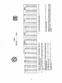
INSTALLATION AND
OPERATING INSTRUCTIONS FOR
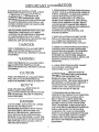
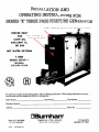
SERIES E THREE PASS FIRETUBE GENERATOR
ASME Stamping plate tack welded to shell
=
T
FORCED DRAFT
FOR Pop riveted to
LIGHT OIL, frontxílue door
GAS/LIGHT OIL,
OR GAS
HOT WATER OR STEAM
7 SIZES:
GROSS OUTPUT —
684,000 to
2,821,000 BTU/HR
© E
For service and repairs to the heating plant, call your Heating Contractor. When seeking information on the boiler,
provide series and size designation shown on rating plate.
Boiler Number Type Firing Type System
Heating Contractor
Address Phone No.
Burnham
Phone: (717) 293-5846 COMMERCIAL STEEL BOILERS P.O. Box 3079
FAX: (717) 293-5877 Burnham Corporation Lancaster, PA 17604
Part No. 8145105R2-7/97
STN
IMPORTANT INFORMATION
BURNER/BOILER SYSTEM, AS USED
THROUGHOUT THIS MANUAL, SHALL MEAN
ALL MECHANICAL AND/OR ELECTRICAL
EQUIPMENT INCLUDING THE BOILER,
BURNER, PUMPS, COMPRESSORS, FEED
WATER SYSTEMS, DEAERATOR SYSTEMS AND
ALL ASSOCIATED PIPING, ELECTRICAL AND
CONTROL SYSTEMS USED AND MAINTAINED
IN THE BOILER ROOM.
THE FOLLOWING DEFINED TERMS ARE USED
THROUGHOUT THIS MANUAL TO BRING
ATTENTION TO THE PRESENCE OF HAZARDS
OF YARIOUS RISK LEVELS OR TO NOTE
IMPORTANT INFORMATION CONCERNING THE
OPERATING LIFE OF THE PRODUCT.
DANGER
INDICATES PRESENCE OF A HAZARD WHICH
WILL CAUSE SEVERE PERSONAL INJURY,
DEATH OR SUBSTANTIAL PROPERTY DAMAGE
IF IGNORED.
WARNING
INDICATES PRESENCE OF A HAZARD WHICH
CAN CAUSE SEVERE PERSONAL INJURY,
DEATH OR SUBSTANTIAL PROPERTY DAMAGE
IF IGNORED.
CAUTION
INDICATES PRESENCE OF A HAZARD WHICH
WILL OR CAN CAUSE MINOR PERSONAL
INJURY OR PROPERTY DAMAGE IF IGNORED.
NOTICE
INDICATES SPECIAL INSTRUCTIONS ON
INSTALLATION, OPERATION OR
MAINTENANCE WHICH ARE IMPORTANT BUT
NOT NECESSARILY RELATED TO PERSONAL
INJURY HAZARDS.
DANGER
1. IF YOU SMELL GAS OR FUEL OIL VAPORS,
DO NOT TRY TO OPERATE THE
BURNER/BOILER SYSTEM. DO NOT TOUCH
ANY ELECTRICAL SWITCH OR USE ANY
PHONE IN THE BUILDING. IMMEDIATELY
CALL THE GAS OR OIL SUPPLIER FROM A
REMOTELY LOCATED PHONE. FOLLOW THE
GAS OR OIL SUPPLIER’S INSTRUCTIONS OR IF
THE SUPPLIER 15 UNAVAILABLE, CONTACT
THE FIRE DEPARTMENT.
2. BURNER/BOILER SYSTEMS PRODUCE STEAM
OR HOT WATER IN A PRESSURIZED VESSEL BY
MIXING EXTREMELY FLAMMABLE GASEOUS,
LIQUID OR SOLID FUELS WITH AIR TO
PRODUCE COMBUSTION AND VERY HOT
PRODUCTS OF COMBUSTION. EXPLOSIONS,
FIRES, SEVERE PERSONAL INJURY, DEATH
AND/OR PROPERTY DAMAGE WILL RESULT
FROM IMPROPER, CARELESS OR INADEQUATE
INSTALLATION, OPERATION OR
MAINTENANCE OF FUEL BURNING AND
BOILER EQUIPMENT.
3. INSULATE ALL STEAM AND HOT WATER
PIPING, FITTINGS AND CONNECTIONS AND
ALL OTHER HOT COMPONENTS AND
EQUIPMENT FROM PERSONNEL CONTACT.
4. ASSURE ALL PIPES, FITTINGS, ELECTRICAL
CONTROLS AND ALL OTHER ASSOCIATED
BURNER/BOILER EQUIPMENT IS OF PROPER
DESIGN AND CONSTRUCTION FOR THE
INTENDED USE AND PROVIDES ADEQUATE
PROTECTION FROM ELECTRICAL SHOCK AND
HARMFUL PHYSICAL CONTACT TO
PERSONNEL.
5. А LEAK TIGHT FUEL DELIVERY CONDUIT
AND CONTROL SYSTEM MUST BE
MAINTAINED AT ALL TIMES.
6. PRODUCTS OF COMBUSTION MUST BE
TRANSPORTED FROM THE BOILER/BURNER
SYSTEM TO THE OUTDOORS IN AN
APPROVED, LEAK TIGHT, INSULATED
VENTING SYSTEM. THE BOILER ROOM MUST
BE POSITIVELY VENTILATED TO PREVENT A
CONCENTRATION OF PRODUCTS OF
COMBUSTION AND A REDUCTION IN THE
AMOUNT OF OXYGEN IN THE AIR.
7. BURNER/BOILER MATERIALS OF
CONSTRUCTION, PRODUCTS OF COMBUSTION
AND FUELS CONTAIN ALUMINA, SILICA,
HEAVY METALS, CARBON MONOXIDE,
NITROGEN OXIDES, ALDEHYDES, CARBON
DIOXIDE, PARTICULATES AND/OR OTHER
TOXIC OR HARMFUL SUBSTANCES WHICH
CAN CAUSE DEATH OR SERIOUS ILLNESS AND
WHICH ARE KNOWN TO THE STATE OF
CALIFORNIA TO CAUSE CANCER, BIRTH
DEFECTS AND OTHER REPRODUCTIVE HARM.
ALWAYS USE PROPER SAFETY CLOTHING,
RESPIRATORS AND EQUIPMENT WHEN
SERVICING OR WORKING NEARBY THE
EQUIPMENT.
WARNING
1. THE EQUIPMENT SHALL BE INSTALLED IN
ACCORDANCE WITH REGULATIONS IN FORCE
IN THE AREA WHERE THE INSTALLATION IS
TO BE MADE. THESE REGULATIONS SHALL BE
CAREFULLY FOLLOWED IN ALL CASES.
AUTHORITIES HAVING JURISDICTION SHALL
BE CONSULTED BEFORE INSTALLATIONS ARE
MADE. ALL BOILER INSTALLATIONS IN THE
USA SHOULD COMPLY WITH THE CURRENT
EDITION OF THE FOLLOWING STANDARDS:
A. AMERICAN NATIONAL STANDARD
ANSUNFPA 31, “INSTALLATION OF OIL
BURNING EQUIPMENT”.
B. AMERICAN NATIONAL STANDARD
ANSI/NFPA 211, “CHIMNEYS, FIREPLACES,
VENTS, AND SOLID FUEL BURNING
APPLIANCES”.
C. AMERICAN SOCIETY OF MECHANICAL
ENGINEERS ASME CSD-1, “CONTROLS AND
SAFETY DEVICES FOR AUTOMATICALLY
FIRED BOILERS”.
2. ALL WIRING ON BOILERS INSTALLED IN
THE USA SHALL BE MADE IN ACCORDANCE
WITH THE NATIONAL ELECTRICAL CODE
AND/OR LOCAL REGULATIONS.
3. INSTALLATION, START-UP, OPERATION
AND/OR MAINTENANCE (SERVICE) OF THIS
BURNER/BOILER SYSTEM MUST BE
UNDERTAKEN ONLY BY TRAINED AND
SKILLED PERSONNEL.
4. FAILURE TO FOLLOW ALL INSTRUCTIONS
IN THE PROPER ORDER CAN CAUSE PERSONAL
INJURY OR DEATH. READ ALL INSTRUCTIONS,
INCLUDING ALL THOSE IN OTHER
BOILER/BURNER SYSTEM MANUALS WHICH
WERE PROVIDED WITH THE EQUIPMENT
BEFORE INSTALLING, OPERATING OR
SERVICING.
5. KEEP BOILER AREA CLEAR AND FREE FROM
COMBUSTIBLE MATERIALS, GASOLINE AND
OTHER FLAMMABLE YAPORS AND LIQUIDS.
6. PROVIDE POSITIVE ASSURANCE THAT
ADEQUATE COMBUSTION AND VENTILATION
AIR IS PROVIDED FROM THE OUTDOORS TO
THE BURNER/BOILER SYSTEM AND THE
BOILER ROOM.
7. DO NOT PLACE ANY OBSTRUCTIONS IN THE
BOILER ROOM THAT WILL HINDER THE FLOW
OF COMBUSTION AND VENTILATING AIR.
8. CAREFULLY READ THIS AND ALL OTHER
MANUALS AND INSTRUCTIONS PROVIDED
BEFORE PROCEEDING WITH THE
INSTALLATION OR SERVICE OF THE
BURNER/BOILER SYSTEM. POST ALL
INSTRUCTIONS AND MANUALS NEAR THE
BOILER FOR REFERENCE BY SERVICE
PERSONNEL.
9. REFER TO BURNER MANUFACTURER'S
INSTALLATION MANUAL PROVIDED FOR
PROPER VENTING OF THE GAS TRAIN
COMPONENTS THAT REQUIRE ATMOSPHERIC
AIR PRESSURE TO BALANCE A DIAPHRAGM.
10. HIGH WATER TEMPERATURES INCREASE
THE RISK OF BURNS OR SCALDING INJURY.
INSTALL AN AUTOMATIC MIXING VALVE AT
THE TANKLESS HEATER OUTLET TO AVOID
EXCESSIVELY HOT WATER AT THE FIXTURES.
11. ALL COVER PLATES, ENCLOSURES AND
GUARDS MUST BE IN PLACE AT ALL TIMES,
EXCEPT DURING MAINTENANCE AND
SERVICING.
NOTICE
1. THIS BOILER HAS A LIMITED WARRANTY, A
COPY OF WHICH IS PRINTED ON THE BACK
PAGE OF THIS MANUAL.
2. IT IS THE RESPONSIBILITY OF THE
INSTALLING CONTRACTOR TO SEE THAT ALL
CONTROLS ARE CORRECTLY INSTALLED AND
ARE OPERATING PROPERLY WHEN THE
INSTALLATION IS COMPLETED.
3. FOR OPTIMUM PERFORMANCE AND
SERVICEABILITY FROM THIS UNIT ADHERE
TO THE FOLLOWING RECOMMENDATIONS:
A. CLEAN FIRETUBES AT LEAST ONCE A YEAR,
PREFERABLY AT THE END OF THE
HEATING SEASON TO REMOVE SOOT AND
SCALE. INSIDE SURFACES OF THE
FURNACE, FRONT AND REAR SMOKEBOXES,
AND REVERSING CHAMBER SHOULD ALSO
BE CLEANED AT THE SAME TIME.
B. HAVE THE BURNER AND CONTROLS
CHECKED AT LEAST ONCE A YEAR OR AS
NECESSARY.
C.RETAIN YOUR CONTRACTOR OR A
COMPETENT SERVICEMAN TO ASSURE
THAT THE UNIT IS PROPERLY ADJUSTED
AND MAINTAINED.
Pama
TABLE OF CONTENTS
SECTION I- GENERAL INFORMATION
Introduction ...................=-e.e=eccoecereee neceser nene een rene eneenen enero no ee Den ee ere oneDnenneen nee
Setting the Unit ..............-..............eee.aercerener canon carnero een rene ere reno ne reee encerrona eee eDeeeeeeeeee
Air Supply/VentiDß EE O O TD
RAtINGS DATA ANO Te
Dimensional Information ...................-.e.-e-secoceocorerane nee reaerrarcanearaceroeeroeoerroencaroncareaecaneraracaraceuerocacenoouercacenncacorevenes
SECTION Il - INSTALLATION INSTRUCTIONS
Boiler Piping........................-.e.ercinoe creen reee een coneenea e ceneo nene nene eee Deneeoeneeoene enero nn.
Steam Trim ............e-e0ccececeneccanrooecarenenreane ne rereacoooreneceoconerenareneneroe roer eeeneneneoneoacernoenecacaoo one ene neon neene neon Deere.
Water Trim N
Burner Installation ......................e..06-eeeccereerencoeneere oe eereneeeee eee ren een econo ceca rerrconrecorecececororoacacenana canon rre cve0es
Tankless Heater Piping .....................e...e=ceseveccrcocene reee nacen acen nene rear rene reeecconeeeceoeorecacenenacencenereoaneoeneereeceooueenaces
SECTION IH - OPERATING INSTRUCTIONS
F1lling SYSÉEIM reo noe eeeneecanereao ce nee ercer ne ene erre e ene ren eoneenenaorranoroncaneneaee nene ene.
Adjusting Bumer .......................=..e..+e.-00merroc reee ooo no ener ne rene reco eCeDoroRrenerneneoooneneocenene roo nneno eno
Testing Controls ........................ecoeecaono nene ereerane nece eRe De Deceneanno nee neeceoen een enene render een recen renDeooenne nenes
Initial Cleaning, Steam Boilers .............-——.-.-e-.e.e-.eseeneeone one eee reee recen enema nen enoeoeececeneoceeoce reee
Initial Cleaning, Water Boilers .....................e....r0eceoceecenr ooo recorre cenee nene een nene recrear rcanenenenenoocannoneaaanannes
Water Boiler Operation .....................e...em0c0nercioo enn enano nene retorne cereooroeconeenene ena recananeee een nora reconoce
Boiler Water Treatment ..........................-..0000000e0erreon aereo enc nneone recreo een enano DeCeneeeee enn enoeoecennne ro nene
pHor Alkalinity Test.................—.e....-.e..erccoccrraaceo ercer een carece career nnereeoenenecacenen encara nene ener nee
Wamings about Frequent Water Addition ....................—.e...e-ee0corcecerec Denon eee ene ren e CCC TR Ree ee
SECTION IV - SERVICE INSTRUCTIONS
Boiler Shutdown and Cool Down Procedures .......................ee..errecererererccer rece e eee rene eaceneecenerecenrenee ener.
Cleaning Boiler Heating Surfaces ...................... e... 0000 nece eneoennenorecanooanneonaannane nacen nerDe nee neenerrenenenene
Reversing Chamber Removal and Installation .................--e.-....ee. ee... rcv sess e sesame
Maintenance of Low Water Cutoff Devices .................=...emeracosnereor recen cese anocaneneaaea ces eneneeeenreerneecareaecconernececenerecee.
Checking Burner dz Controls ...............—.—..e-...-e.e.eseceneene rene Dane rDe reee eoreene ren Ccen en neceno creeo nene Deere eee
LUDTICAÎION N
Checking Safety Valve .................eeeecceeccoooeocro ercer ercer ereearaere reee rdareeonacnereecaconececcrrenacnacamaceeoreaa rene renenecas
General Maintenance Considerations .......................reccesrecvenorococeicao reee reee neacee ein n ener eannane ranas recee ener.
Attention to Boiler while not in Operation .........................-.ee0merceocc rre rene reee eee canes rereneerecenrenenveenecerneces
Ordering Repair Parts ....................e....eeeeceooneeoer ere Reena ne nee ee nee e eee een ene Le Cero ene ene
Reference Drawings ...........—e....eceeeereccoorrecocroncrcceo caca neeencenoeeeneaerencareancancarrecarecarnarearereecaraconarerencaceaecenrrerrececencaaree
Pertodic Testing Recommended Check List .........................esceccrcerconcccorenaceacereoacarenreeere errar nrrnenacereceeraereeceneecaeree
Terms and Conditions of Sale .........................e.e...meocer cera sonanenaa eo rereeren e oerenoerencenarenenaasrcaneacereceno roce rraencenereoanercroe
wn > в +
SECTION I — GENERAL INFORMATION
(1) GENERAL INFORMATION
The E Series is designed specifically for forced draft firing, is
available with light oil, gas, or combination gas/light oil burners,
and operates with a combustion efficiency of over 80%.
In addition to the advantages of forced draft firing — the
elimination of the need for external draft devices such as a
high chimney or mechanical draft equipment — the E series
offers such features as: Compact, 3 pass firetube design, pack-
aged unit that will fit through a standard doorway; Light-
weight vacuum formed reversing chamber; Provision for
instantaneous hot water tankless heater; 7 models ranging
from 684 MBH to 2821 MBH gross output.
This manual gives the necessary information for the proper
installation, operation, maintenance, and service of the units.
For special installation problems, contact Burnham Corpora-
tion, Commercial Steel Boilers, PO. Box 3079, Lancaster, Penn-
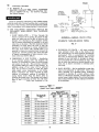
sylvania 17604. Dimensional information is given in Figures
3A and 3B. Ratings and data are given in Table I.
(2) INSPECT SHIPMENT carefully for any signs of damage.
A. ALL EQUIPMENT is carefully manufactured, inspected
and packed. Our responsibility ceases upon delivery of
boiler to the carrier in good condition.
B. ANY CLAIMS for damage or shortage in shipment must
be filed immediately against the carrier by the consignee.
No claims for variances from, or shortage in orders, will be
allowed by the manufacturer unless presented within sixty
(60) days after receipt of goods.
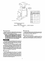
(3 SETTING THE UNIT
Front and rear heads are equipped with two lifting eyes
each to be used in maneuvering the boiler into position. The
boiler can also be rolled into position on a series of pipes.
The unit should be located in the boiler room so as to pro-
vide ease of venting and adequate clearance for maintenance,
serviceability and installation of piping. The tube pull space
listed in Figures 3A and 3B must be provided at either the
front or rear of the boiler. Firetubes may be cleaned from the
front of the boiler without disturbing the reversing chamber.
Care must be taken so as not to damage the reversing cham-
ber with the end of the flue brush. The reversing chamber
pull space must always be provided at the rear of the unit, see
Figures 3A and 3B. The coil pull space listed in Table II must
be maintained at the front of units equipped with tankless
coils.
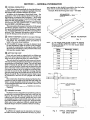
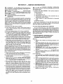
Floor construction should have adequate load bearing char-
acteristics to bear the weight of the boiler filled with water (see
Table I). A boiler foundation similar to the one shown in Figure
1 is recommended if the boiler room floor is weak or uneven or if
a water condition exists.
These boilers are not approved for installation on combus-
tible flooring.
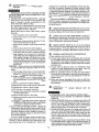
(© CHIMNEY OR VENT
The E Series boiler is designed for forced draft firing and may
be used with a conventional natural draft stack or stub vent (see
Figure 2). For proper Vent Size, see Figures 3A and 3B. Draft
controls are not normally required, although they may be used
on installations where a natural draft stack is used or on mul-
tiple boiler installations with a common stack. If high breeching
drafts make burner adjustment difficult, a locking blade type
adjustable damper should be installed at the boiler breeching.
(5) AIR SUPPLY
A sufficient air supply must be maintained at all times to
the boiler room for proper performance of the unit. A perma-
nent opening or duct should be provided so that the boiler
input will not exceed 4,000 Btuh/in? of free area.
Example: Model E-20 Firing Rate (Gas) = 877 MBH
877,000 BTUH _
4,000 BTUH/In? 7 220 In’ Free Area
CONCRETE SD.
>
N L'
~~ sour FOUNDATION
Fig. 1
NOTE: IF THE BOILER ROOM FLOOR IS WEAK OR UNEVEN
OR IF A WATER CONDITION EXISTS, A BOILER
FOUNDATION SIMILAR TO THE ONE SHOWN ABOVE
IS RECOMMENDED.
>
Boiler Dimension - Inches
Model “pr
E-20 60
E-30 72
E-40 83 /
E-50 88 `
Е-60 97
Е-70 106
Е-80 115
SMOKEPIPE - DO NOT REDUCE BELOW
yr SIZE OF COLLAR ON REAR
SMOKE BOX.
FRONT OF
"BOILER
FLUE al
Fig. 2 TYPICAL ARRANGEMENT
FOR STUB VENT
O,
d
|
“¡9A9] EOS
элоде 1994 (0001 Чэеэ 104 %# JO 9184 9,4) jE poonpa! aq pnoys
SBUIJE4 OUI “POIEIIPUI SSOU) SAOG2 SOPNINIIE 104 ‘sed uo 399} 0002,
pue ¡10 uo 3984 OOOT 03 dn sopnyije je Ajdde anoge umoys ssuney
‘Jojano an} 19|t0G 328 ains
-Soid UUIN(OI J938M LOT + 09 % % ZT uo paseq sie s3ujjel 1a|109
"HAW ‘SZUNEY 19N
¥=g=]| JO siseq UO 18/10 129195 ‘saimeladway Jsjem 13Y9IY 104
"UISISAS ul aunjeladiua) J9)eM
эВезеле 4.0/1 Чо рэзед эле ‘Joa; asenbs ‘лезем 104 SBUNEJ aN
"039 ‘wa)sAs Виа эл15
-u9IX3 “uoNEeJado wejsAs Juda iLLIAdIUL Se yans ‘sjuawadinbals dyoid
pue 3uidid |ensnun 3uiAey suoljejjeisul Joy Jainioejnuew INSUOJ
‘191eM
40) GI'T puke weals 104 88Z'T 01 ESE'T Woy Alea ydiym sajue
-mo|je dnyoid pue 3uidid uo paseq ale umoys s3uiges1iduy =g =| (2)
‘раду HO-SE3 UONEUIQWOI SIZEI
"uojes 19d N1g 000'0PT JO aNıBA Jeay e -1pu! ,,09,, ‘P@sly-[IO sajediput ,0,, “Paly-sed sajeaIpul ,,9,, XIINS
Suey 10 3481 чо расед 5! Наб U! Aldedea лэшапа y=g=| our (€) ‘лезем 154 O€ sajedlpul ,,M3,, ‘weals {Sd GT saiedipul 3, Xijald (1)
18974 0999 9017 ТОР GOE OE LT 9vE OcE SLYE O'te ESVC 061 GCT6 128¢ E 78 08-3
0999 6564 CELE TSE LAC LL SI 140 082 ESOE OIC OPIC TT6I E£96Z 1976 GEL 0Z-3
£98S £929 T9£E 00€ 82¢ ECT 19¢ ote 0£9¢ ¢'81 8281 CEST 0089 COTC 89 09-3
L90S 4957 c86C OSc O6T OZ'CT 61¢ 006 LOGE ¿SI OTST ZvET £199 EVLT Tes 06-3
£E9V7 2110) 4 0LS¢ 466 ЗАТ TO OT 941 091 BEZT OCT 6lcl E9OT (SYA 44 СОРТ 6Tt 071
8EGE BECE LETC 891 CET 778 CET OeT BOET Тб 706 ¿BL 8GcE EVOT CTE 0g-3
£€9¢ ¿ve Yell 60T 98 889 88 08 148 T9 ses ETS BETC 789 70€ 06-3
лэзелл weals sq J91eM weas 1} no opIsIjeM | episest4 (yqui) (uds) 1938M weals шеэ}5 HaW эн Jaquunp
sq - [Ind JYSISM suwunjoA sep die 34317 Haw HEN H'bS nding 43]10g 13109
уча Aq ‘se, a9euny ‘14 ‘bsg Ayiveden $5045) (1)
‘xosddy ‘xo1sddy JUBJUO7 19 EM 32euns Зипеэн (€) 1euung H—9g=l (2) sduiJey y=—g—1 JON H=—g=i
viva —= ~~ SONLLVY
I 319V1
и
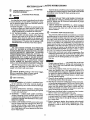
VE ЭН
NOILVIWNHOANI TYNOISN3IWIA
4371109 WVALS
MIA IAS THO MATA LNOYA
"J91LON LNOHLIM 3ONVHD OL 3sv8 QUVANVLS |
193rgns 3uv vi1vO ONY ‘SNOISNINWIC ‘SNOILYD14103dS ‘2 A -
'031Nddv 1300W ¥INYNG NO 35v8 Nodo C | | |
9NIANId30 "CINS ONOA38 193MOWd AVN H3NNNE 9
М1 SSII HLOIM TIVY3A0
“VLVO TVNOISNSWIG ONV SONILVY 2 NIVHO ONY >
H3ILVIH SSIDINVL YOJ E 318V1 335'SN31v3H FTe— NMOOMO1B © —a|| }—=—,2
SSITANYL HLIM 03ddIND3 SLINN JO LNOHJ ЭНА " " 7
LV O3NIYLNIVN 38 LSNW 30VdS 11nd 10D 3HL 5 y 7 1 \
"03ZLN 38 wd LE ;
AYW 39vdS TINd 39N1 YV3Y YO 1NOYJ YAHLIS $ + = -- На ——————]—
O en
(08-13 N
wow 2 1HOIS HL ob) J
NOLLO3NNOD 430-MOTI FI (1) - d33d LNOHSYM FI LNOHSYM £1
SNOLLOBNNOD # (2) - 437108 WVALS NO QYVONYLS " 3 " И
- - NOILIINNOD
NÓ 3015 L437 NO 0319901) -SONlddYL IWNOILIGOY € NENL3N 7 == | LNOHSYM
I I |
‘SAN 31VW35 O3OV3YHL 3HV SONILLI4 "I en “E y
H3HLO T1W*39Nv14 "61 OSI SI NOLLDINNOS ,9 2 | E —+-— Ma --+-—— ———————— A | -
'SIHONI NI 34V SNOISNINIO TIV "1 32vdS TINd -
S310N NN MENIT YIONVHO AE 4108 ‘SONI Lis M
RX — NANTOS SILVA |
4
[ + 3000 SS5309V YUY3IY < ng
vv] v] »| 5%] Ze] Ye | 3718 NOLLOSNNOD NHML3Y — 7, 1 oi X
si[ si] si] si] ti] vi] ti] Zoves Tong usewvHo - A Г | a HSM
т 7 77777 |
$94] $92|#92|#9t | ez) ve | ve | LHOIFH 133HS 3801 -X | ож
£, 3LON 335) Y sSV19 39NV9—.
®| #9) $ | 3193109] oe os змп U3LVMIVWNON -AR| Y SONI oN 23s) |
19 | 26 | ++ | se| se | vz | El | MVad-30vds "ла Зета - A| 01 o A de > J
EZ | 9 | 95 | 2b| 9b | sE | bz |IINON4-39Vvds TiNd 38NL - M | -Ф— " 1
Lo LA scope HO mw | | Fee eee
с | 6| 5 | $5 | + | sv! Y | NOOO! AJO-LNO H31VM MOT- | | I To } OL 93d 13m MN \ Г a Ш
at ai X08 3MOWS LNON3 3 /
| Vs] Fc] Vs] Vs] Vr| Fr] Fe NolLvOON sSVI9 3onvo - $ | | 6 — NA —— - 7”
61| 61| si) 1 | Ae o Ye INOLVIOT NAMIO9 HILYM - Y | I— с =— “YNOLLdO —1lo9 NN 7
YeclYzol Lec Lec - = Пра N 7
rec Tes Tec Tec $20 Tuc fzal —1HOISH HYTIOS 1N3A - "I TT Y3LVM LOH 911S3WOd NI ho =>"
| Ln Bn! Bn] e] He! Ue] varamviA uYT109 INIA - wooa al ed МН А dr ral O Ins. O
61! el | Er | El | BI | 91| 9! HOIIH I9VNENJ - N xog MOWS — 5 N = ‘
1 uv3y / = 39vdS TInd 38nL =
+92) 492) Lo) $92) sz | sz | sz [ LHOEH NOLLOINNOD NuNLZY-A| | OZLVINSNI NL JANA/ (24 3LON 33) 7 — H— n 3909
9| 9] 9] 9 v| v| v| 3ZIS NOILOINNOD AddnS - MI NOILOZNNOD Y 3
se | № | 9г | гг | гг | 1 | II | NOLIVOOINMNISE/AIddns - $ г
е| fof Fe Fe] F2| +4] #4 нааза хов lows змоза - Же я H+ #1
62/67/62 Vez Usa Aso Yoz| LHOI3H X08 IMOWS 1N084 - D a
601 | 001| 16 | 28 | 22 | 99 | ys | HLONZ1 3SvG QuvanuLs - +
ba|-fs2|-H09|-#25/-Fos| sb |Æec) HLON3T 3sVE TvNoLdo - A (+. 31ON 335) LON 33S)
-c6|-Hoa 8. -MeslAosA-cs 9 >>) HLONIT TIVH3AO H3llos - (I * A 32vds Nd 1105
toute. [Farle Posi 1H9I3H Y108 - Y) 39498 Tind 38anL
ce|Fez|éco|Roc|Fcs| tb |Æee! — HLIN3T TIaHS 837108 - A]
$ve|$te] 4ve] See! 1€ | 1€| te HLOIM U31108 - Y
08-13l02-13|09-13109-Tal0»-13|0€ -13/02-13 STAAdON 431108
"3IILON LNOHLIM 39NYH2 OL
193KENS 3ÿv YLVO ONY 'SNOISNIMIO'SNOILYOIAl93dS
’0311ddy 1300N YINHNE NO
9NIANIdIO 'JdIMS GNOAIE LIIr0Wd AYN Y3NUNE
10 J1YNOISN3WIO ONY SONILYU
HALVIH SS3TWNVL HOJ D 370VL 3358 'SHILVIH
SSITHNYL HLIM Q3d4dIND3 SLINN JO LNOH4 IHL
LV OANIVLNIVA 36 1SNW 32¥d4S 100d 1109 3HL
"QIZMILA 39
AV J2VdS 11d 39n1 HY3H HO 1NOH4 H3HLI3
“SdN 3TvW34 O30vaYHL 3uY SONILL TI
*'SIHONI NI 547 SNOISNIWIO TIY -
«
— in
SALON
SI | Si) Si | Si ) bl | 1 | bi | 39Vds TIiNd YH39WYH2 - A
592) $9c|#92|#92 | ez | vi | bi | LH9|3H 133HS 389NL -X
Her Ja Se] Ja EES ONIdid NOILY1NOHID38 - M
19 | 26 | »b | SE | SE | v2 | €! | HV3Y-30VdS TlNd 3801 - À
64 | +9 | 9 | Zb| 9b | SE | b2 IINOM4-32vdS TINS 380. - (À
Bos | Tes 5.05] 2] ег) Tia] À © | NOUVDON 440-100 V31VM MOT- Î
e Vee| Vee| Fee] Fai[ Vei[ F1] SNOILIENNOS LVISVNOV - $
b | + | У | » | + | #€| ZE |NOILVDOT NWNTOO S31VM -
Tec Tes eses Sua Tuc) Pza —1H9I3H HYTIOS INSA -"T
| Lu ul Bn] 2 e| Ye] Ue] YI13AVIA UY TIOS 1N3A - dl
6 | el | El | El | AI | 81] MY LHO9I3H 353VNHNZ - N
$ ail $ai| 4er] $ei] 91 | 91] Fe NOILVIOT ÆlddNS - IM
в | t|b || [42] г 3Z1S NOILIZNNO9 dOL_- H
bi| vi] Évi] Fer) ferlfoi] 2 NOILYI07 NUNL3Y - MP
e| Tal Tal fo | 22| 72 H1430 X08 3M0WS 1NoY4 - El
62| 46267 as Aoz|Vez|1H9I3H XOB 3HOWS LNOHJ - Y
601| 001 | 16 | 78 | 44 | 99| bs | HI9NII 35vE ayvaNVIS - |
ve|fa2|E00|-Luc|-Pac| sb | Fee] HLON3N 3SV9 WNOULdO - Я
rse|-Fge| 8z |-Rca|Xoo|R-cs|?r»| HLONIT TIVHIAO HIllos - (I
FUI UNS LU] Fu |R S2] Rss |B vu JH9I3H yznog - 3)
co|-LuzEco Los | Tas! о» ze H19N91 TI3HS YHlog - El
fuel £ +6] vel 1E| IE] 1€ HLOIM 837108 - VW
oe-wajou-mals-#a{orn3|orns|ocw3|se-a| GS TIQON T1108
ge "Old
NOILVINHO4NI TYNOISNIWIA
437109 H31VM
"M3IA 3041S ГНОМ
3SV6 OYVONVIS J
3sv8 TVNOILdO q
Ÿ
MALA 1NO#4
WBl SSII HLOIMA TI1VH3AO
LI 8
(b, 3LON 33S)
Ai
33VdS T1Nd 390L
ANVL NOISNYdX3 /1LN3A HIV
310N 335)
3IYds T1nd 1109
2 NIVIO ON >
TF NMOONOTE 117 ——| pe 2
TT 7
wd Г
+ fT OO I III SOIT
-— ME LL EE
os-M3 | N
1H9IS NYHL Ob-M3) 5
d33d LNOHSYM $1 LNOHSYM $1 |
|
1
I |
LR + PR - | |
HIN Y3BWVHD waned H1O0@ SONILLIJ |
A — NANO ¥3LVM I \ |
[ -———HOOQ SSI59V Hvay > |
LA a —— Y00d 1N0u3 |
| | I1198VAOW3Y | |
E 1 SNOILIINNOD
| 1Y1SVNOV
со’ $ |
d hen A | !
Э К +
| A T || M13HS OL C3913M ! г---------- 1
35NV9—/ 1 : ~~— X08 3MOWS 1NOHJ \\ | /
= e WE La \ Lo vs == an 3 / /
M Г | = Л \ \ ИХ
Я IWNOILdO -109 NN „у
H3LYM LOH OILS3WOQ NS Ha
3000 y 5 O SD 1 Le и” О
xoa 3»wows /IK_---- AT dr N ET” /
a3 Jy ad / JT 39vds 1nd 3anl cr
19 INSNI
Addns MI = fl ;
ONILLIS
INIA Alas NN139 М
22 — 7 дао Н -—_i — £1
a “
SECTION II
"Y" FITTING
—
=
—GATE VALVE
PREFERRED HARTFORD RETURN CONNECTION
GRAVITY RETURN
CLOSE OR SHOULDER
NIPPLE
——
GATE VALVE
——
ALTERNATE HARTFORD RETURN CONNECTION
GRAVITY RETURN
FRONT OF BOILER
INSTALLATION INSTRUCTIONS
STOP VALVE
\ SYSTEM SUPPLY
© 7 REDUCER
prs
©
(A)
\/
ASME
SAFETY VALVE
BOILER MAKE-UP
WATER
(A)
LOW WATER CUTOFF \ [0 с
CONTROLS RE NW.L
A . WL.
- Г > \ CHECK
GAUGE GLASS A © Q ZA
| iowesr PERMISSIBLE
© y ‹ WATERLINE
STEAM GAUGE > \
~~ | \ STE PIPING
0 у \ DETAIL
SIA TO } 5
e DRAIN \
| | O |
! |
IY
(A ) © GRAVITY
- RETURN
CHECK VALVE
(SEE NOTE #1. }
BLOW-OFF VALVES FOR
FLUSHING BOILER AND SYSTEM
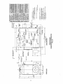
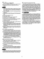
RECOMMENDED BOILER PIPING - STEAM BOILER
GRAVITY RETURN
“Е- 20" = "E- 80 un
SUPPLY BOILER
TO MAKE -UP
SYSTEM WATER
ALL STEAM TAKE-OFFS STOP Check
FROM TOP OF HEADER VALVE pas
/ REDUCER
р STOP
ASME y VALVE
SAFETY OVERFLOW STEAM A
VALVE © TRAP 2" TO 4" » RETURN
> ABOVE NWL (> SYSTEM
© , oraın | Boiler Piping Size (Inches)
р VALVE
N Number | Supply-A | Return-B |Equalizer-C
- 1 1
PRESSURE CONTROLS GATE E-20 4 2% 2%
| VALVE E-30 4 2% 27
CD
TO E-40 4 27 27
STEAM PRESSURE GAUGE DRA IN RECE | VER
9 CHECK TANK E-50 6 4 4
(D) VALVE
STOP E-60 6 4 4
ho
GAUGE GLASS SOLENOID
> VALVE VALVE E-70 6 4 4
(1F REQUIRED)
> E-80 6 4 4
(TA For D, see Note 4
A 0 PUMP CONTROL/LOW WATER CUT-OFF
BLOW -OFF
VALVE
FRONT OF BOILER TO DRAIN
BLOW -OFF
VALVE
RECOMMENDED BOILER PIPING - SINGLE STEAM BOILER
“E-20" - "E-BO" PUMPED RETURN
NOTES:
(1) Return loop connection was designed to eliminate necessity of check valves on gravity return
systems, but in some localities a check valve is a legal requirement.
When pump discharge piping exceeds 25 ft. install swing check valve at pump discharge.
If pump discharge is looped above normal boiler waterline, install a spring-loaded check valve
(2)
3)
(4)
at return header and at pump discharge.
piping tables.
MINIMUM PIPING REQUIREMENTS — STEAM BOILERS
Fig. 4
8
Pumped return piping size (D) must be calculated using pump size, distance, and standard
EXPANSION TANK
SYSTEM RETURN
SUPPLY TO SYSTEM
NN TEMPERATURE /
~ / pressure GAUGE
10
\ RECIRCULATION
| / reine
ASME SAFETY
RELIEF VALVE
BOILER | PIPE SIZE [INCHES)
MODEL | suppLy-A | RETURN - 8
EW-20 2 2
EW -30 27 25
EW-40 3 3
EW-50 4 4
EW-60 4 4
EW-70 4 4
EW-B80 4 4
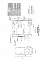
RECOMMENDED BOILER PIPING - WATER BOILER
il EW-20" — u EW-80"
MINIMUM PIPING REQUIREMENTS — WATER BOILERS
Fig. 5
TT
(1) BOILER PIPING
Attach flow and return piping lines and insert plugs and
bushings in connections as required. Flow and return piping
headers are detailed in Figure 4 and Figure 5.
CAUTION — IT IS IMPORTANT TO COMPLY WITH THE
MINIMUM PIPING REQUIREMENTS IN ORDER TO
ENSURE MAXIMUM PERFORMANCE AND RELJABIL-
ITY. PARTICULAR ATTENTION SHOULD BE GIVEN
TO THE CONSTRUCTION OF THE STEAM HEADER
AND HARTFORD LOOP ON STEAM BOILERS.
WARNING:
The nominal temperature differential between supply and
return water recommended for Burnham Series E water boil-
ers is 20°F. As a precaution against thermal shock, this differ-
ential should never exceed 40°F.
The boiler should not be operated for any length of time at
a temperature setting that allows the formation of conden-
sate in the tubes or smokebox. This generally dictates a mini-
mum setting of approximately 170°F on the low limit on sys-
tems with a 20°F system differential. On cold start up, con-
densation can be expected until the boiler warms up. If for-
mation of condensate persists, the low limit should be adjusted
upward until condensate no longer forms.
(2) STEAM TRIM
Install the gauge glass trim in the two (2) %” couplings
located at the front right side of the boiler. Mount the pres-
sure gauge in the 2” threaded connection located at the top
of the front head. Install the safety valve in the connection at
the top, rear centerline of the boiler. Install the drain valve in
the connection at the bottom rear centerline of the boiler. The
connections are labeled in Figure 3A.
(3) WATER TRIM
Install the combination pressure-temperature gauge, drain
valve and pressure relief valve as shown in Figure 5. Connec-
tions for the trim are labeled in Figure 3B.
(© BURNER INSTALLATION
Refer to burner manufacturer’s installation manual fur-
nished with the E-Series boiler for proper installation, fuel
piping, wiring, burner adjustment and service instructions.
(5) TANKLESS HEATER
A. IF BOILER IS ORDERED WITH TANKLESS
HEATER, CONNECT TANKLESS HEATER PIP-
ING AS SHOWN IN Fig. 6. See Table II for Tank-
less Heater Ratings.
Install an automatic mixing valve at the tankless heater
outlet to avoid risk of burns or scalding due to excessively
hot water at the fixtures. Adjust and maintain the mixing
valve in accordance with the manufacturer's instructions.
B. THE FOLLOWING GUIDELINES SHOULD BE
FOLLOWED WHEN PIPING THE TANKLESS
HEATER:
1. FLOW REGULATION — If flow through the
heater is greater than its rating, the supply of ade-
quate hot water may not be able to keep up with
demand. For this reason a flow regulator match-
ing the heater rating should be installed in the cold
water line to the heater. The flow regulator should
preferably be located below the inlet so that the
regulator is not subjected to excess temperatures
that may occur during “off” periods when it is
possible for heat to be conducted back through the
supply line. The flow regulator also limits the flow
of supply water regardless of inlet pressure varia-
tions in the range of 20 to 125 psi.
2. TEMPERING OF HOT WATER — Installation
of an automatic mixing valve will lengthen the
delivery of the available hot water by mixing some
cold water with the hot. This prevents excessive
and possibly scalding hot water at the fixtures. In
addition, savings of hot water will be achieved
since the user will not waste as much hot water
while seeking water temperature to his liking.
Higher temperature hot water required by dish-
washers and automatic washers is available by
piping the hot water from the heater prior to
entering the mixing valve. The mixing valve should
be “trapped” by installing it below the cold water
inlet to heater to prevent lime formation in the
valve.
HIGH TEMP
TEMPERED WATER FOR QUTLET INLET
AUTOMATIC O
HOT WATER WASHERS. ETC
TO FAUCETS ‚ ЕТС,
AND SHOWERS
OSE BIB
IN HOT WATER
LINE FOR |
PERIODIC
FLUSHING OF
SEDIMENT,
COLD
WATER
SUPPLY
TABLE ||
TANKLESS HEATER RATINGS
(Steam and Water Boilers)
GLOBE VALVE _ 37
OR SQ. HD. ®
e HD. COCK NN auTOMATIC
Y td
TANKLESS
HEATER
MIXING VALVE
FT Ч >
' —— О
FLOW REGULATOR
SAFETY IN COLD WATER
RELIEF LINE AT LEAST 3 FEET
AHEAD OF TANKLESS HEATER
VALVE
SCHEMATIC TANKLESS HEATER PIPING
SCHEMATIC TANKLESS HEATER PIPING
FIG. 6
. FLUSHING OF HEATER — All water contains
some sediment which settles on the inside of the
coil. Consequently, the heater should be periodically
backwashed. This is accomplished by installing
hose bibs as illustrated and allowing water at city
pressure to run into hosebib A, through the heater,
and out hosebib B until the discharge is clear. The
tees in which the hosebibs are located should be the
same size as heater connections to minimize pres- .
sure drop. :
`
. HARD WATER — May be applicable to some city
water and particularly to well water. Have your
water analyzed by a qualified water treatment
specialist to determine if a water softner, condi-
tioner or filtration is required. Treated water will
ensure longer tankless heater life and performance
and is also beneficial to all the piping and fixtures
in the building.
Rated Capacity
Gallons Heated 40° to 140°F
with Boiler Water Temperature @
Heater For Use on the Heater Coil
Coil Following Boiler 180°F 180°F 212°F Pull Space
Number Sizes: GPM GPH GPH Inches
INA-200 E20 3.5 210 325 16
INA-210 All Sizes Except E20 3.5 210 325 2414
INA-300 All Sizes Except E20 5.0 300 466 29
INA-360 All Sizes Except E20 6.0 360 560 241
INA-450 Al! Sizes Except E20 7.5 450 700 29
INA-600 E60 and Larger 10.0 600 933 45
INA-750 E60 and Larger 12.5 750 1165 49
INA-900 E40 and Larger 15.0 900 1400 41 /
INA-1125 E60 and Larger 18.7 1125 1750 49 >
INA-1350 E70 and Larger 22.5 1350 2100 59
INA-1500 ESO 25.0 1500 2330 69
10
TN
SECTION III OPERATING INSTRUCTIONS
ALWAYS INSPECT INSTALLATION BEFORE
STARTING BURNER.
(2) FILL HEATING SYSTEM WITH WATER.
IMPORTANT
Any time that raw water is introduced into the boiler
it must be heated to at least 180°F immediately to dissi-
pate the dissolved gases which can otherwise cause in-
ternal corrosion to the boiler.
A. STEAM BOILERS — Fill boiler to normal water line
as shown on figure 3A. Water should be visible in the
gauge glass. After boiler is in operation, make up water
should be added slowly to maintain the water level.
B. HOT WATER BOILERS — In a hot water heating
system, the boiler and entire system (other than the
expansion tank) must be full of water for satisfactory
operation. Water should be added to the system until
the boiler pressure gauge registers normal system design
operating pressure. To ensure that the system is full,
water should come out of all air vents when opened.
WARNING
ON A HOT WATER SYSTEM THE PRESSURE
MUST NOT EXCEED 30 POUNDS UNLESS THE
BOILER IS ESPECIALLY DESIGNED FOR A HIGHER
MAXIMUM WORKING PRESSURE. IF BOILER
PRESSURE EXCEEDS PRESSURE SETTING OF
SAFETY RELIEF VALVE, VALVE WILL RELIEVE
IMMEDIATELY, BUT CAUSE OF RELIEF MUST BE
INVESTIGATED AND CORRECTED. EXCESS PRES-
SURE IS DANGEROUS, IN ADDITION, COULD
CAUSE DAMAGE TO HEATING SYSTEM, PER-
SONAL INJURY OR SERIOUS PROPERTY DAMAGE.
DO NOT draw water from boiler while in use. When
adding water while boiler is in operation, do not open
supply valve fully but add water slowly.
3) ADJUST BURNER according to the burner manu-
facturer's specifications. Refer to burner manufacturer's
installation manual furnished with the boiler.
(4) TEST CONTROLS
WARNING
Before Installation of the boiler is considered com-
plete the operation of the boiler controls should be
checked, particularly the low water cutoff and the high
limit control.
A. CHECK OPERATING CONTROL OPERATION.
Raise and lower operating control setting as required
to start and stop burner.
B. WARNING — CHECK HIGH LIMIT CONTROL
Jumper Operating Control Terminals. Allow burner
to operate until shutdown by limit. Installation is not
considered complete until this check has been made.
REMOVE JUMPER.
C. CHECK LOW WATER CUTOFF control with water
level at normal water line (see Figure 3A). Raise op-
erating control setting to allow burner to operate.
Open boiler drain to allow water level to drop to bot-
tom of sight glass until burner operation is shut down
by low water cutoff.
11
Close boiler drain and refill to normal water line. Unless boiler
is equipped with a manual reset low water cutoff, burner should
automatically restart during fill. Reset operating control.
IMPORTANT
PROBE AND FLOAT TYPE LOW WATER CUT-OFF DE-
VICES REQUIRE ANNUAL INSPECTION AND MAINTE-
NANCE. Refer to step @ of Service Instructions for proper
cleaning instructions.
D. CHECK OPERATING CONTROL on a boiler equipped
with a tankless heater. With burner off, draw hot water
until burner starts, then turn off hot water and check
burner shutdown.
6) CLEANING A NEW STEAM BOILER
Oil, greases & sediments which accumulate in a new boiler
and piping must be removed from the system in order to pre-
vent an unsteady water line and carry over of the water into
the supply main above boiler. Operate the boiler with steam
in the entire system for a few days allowing the condensate to
return to the boiler. If the condensate can temporarily be
wasted, operate boiler only for the length of time it takes for
condensate to run clear. If the latter cannot be achieved or if
the condensate is returned to the boiler, boil out the boiler
using the SURFACE BLOWOFF connection. Refer to figure
3A, note 3 for location of surface blowoff connection.
A. Drain boiler until water is just visible in gauge glass. Run
temporary pipe line from the surface blow-off or safety valve
connection to an open drain or some other location where
hot water may be discharged safely. Do not install valve in
this line.
Certain state and local codes may restrict the use of some
of the chemicals listed for cleaning and maintaining the
boiler. Check with local authorities before proceeding to
use any chemicals.
B. Drain about 5 gallons of hot water from boiler into a con-
tainer and dissolve into it the appropriate amount of a
recommended boilout compound. Additional containers may
be required to dissolve sufficient chemicals for large mod-
els. Remove safety valve and add solution to boiler water
through exposed tapping.
C. Close all valves leading to and from the system to isolate
the cleaning solution from the system.
D. Start burner and operate sufficiently to boil the water with-
out producing steam pressure. Boil for about 5 hours. Open
boiler feed pipe sufficiently to permit a steady trickle of
water from the surface blowoff pipe. Continue this slow
boiling and trickle of overflow for several hours until the
water coming from the overflow is clear.
E. Stop burner and drain boiler in a manner and to a location
that hot water can be discharged with safety.
E When the boiler has cooled down to 120°F or less refill boiler
to normal water line. If water in gauge glass does not appear
to be clear, repeat steps A through E, boiling out the boiler
for a longer time.
G. Remove temporary piping, plug tapping and/or reinstall
safety valve. Boil or bring water temperature to 180°F
promptly in order to drive off any dissolved gases in the
fresh water.
(6) CLEANING A WATER BOILER
The oil and grease which accumulate in a new hot water
boiler can be washed out in the following manner.
A. Remove safety relief valve using extreme care to avoid dam--
aging it.
Certain state and local codes may restrict the use of some
of the chemicals listed for cleaning and maintaining the
boiler. Check with local authorities before proceeding to
use any chemicals.
. Add an appropriate amount of recommended boilout
compound.
. Add solution through exposed tapping, and reinstall safety
valve.
. Fill the entire system with water.
. Start firing the boiler.
Circulate the water through the entire system.
G. Vent the system, including the radiation.
H. Allow boiler water to reach operating temperature, if possible.
I. Continue to circulate the water for a few hours.
J. Stop firing the boiler.
K. Drain the system in a manner and to a location that hot
water can be discharged with safety.
L. When the boiler has cooled down to 120°F or less, remove
plugs from all available returns and wash the water side of
the boiler as thoroughly as possible, using a high-pressure
water stream.
M. Refill the system with fresh water, and bring water tem-
perature to 180°F promptly in order to drive off any dis-
solved gases.
ATED a E
(7) WATER BOILER OPERATION
The following guidelines relating to system water tempera-
ture fluctuation and flow through the boiler must be observed.
A. It is important to operate your boiler in such a manner as to
prevent temperature fluctuation of more than 40°F at any
time. Rapid temperature changes within the boiler can create
stresses in the boiler metal. These stresses can cause damage
to the boiler by loosening tubes, or in more severe instances
can crack tube sheet ligaments, furnaces, or waterlegs.
B. It is equally important to insure that there is circulation
through the boiler of at least 1/2 GPM/BHP at all times
when the burner is firing.
BOILER WATER TREATMENT
Boiler water treatment will help maximize the effective-
ness and. prolong the life of pressure vessels.
The general objectives of boiler water treatment are:
A. Remove corrosive gases from feedwater and boiler water.
B. Prevent sludge and scale deposits on the water side heat-
ing surfaces.
C. Prevent foaming and carryover.
Consult with a local water treatment company regularly en-
gaged in the treatment of boiler water for advice on maintaining
the proper feedwater, boiler water, and condensate chemistry.
Certain state and local codes may restrict the use of some of
the chemicals listed for cleaning and maintaining the boiler. Check
with local authorities before proceeding to use any chemicals.
12
(9) MAKE PH OR ALKALINITY TEST
After boiler and system have been cleaned and refilled as
previously described, test the pH of the water in the system.
This can easily be done by drawing a small sample of boiler
water and testing with hydrion paper which is used in the
same manner as litmus paper, except it gives specific read-
ings. A small color chart on the side of the hydrion dispenser
gives the reading in pH. Hydrion paper is inexpensive and
obtainable from any chemical supply house or through your
local druggist. The pH should be higher than 7, but lower than
11. Add some of the washout chemical (caustic soda), if neces-
sary, to bring the pH within the specified range.
(OR IMPORTANT
If, during normal operation, it is necessary to add water to
this boiler more frequently than once a month consult a quali-
fied service technician to check your system for leaks. À leaky
system will increase the volume of make-up water supplied to
the boiler which can significantly shorten the life of the boiler.
Entrained in make-up water are dissolved minerals and oxy-
gen. When the fresh, cool make-up water is heated in the boiler
the minerals fall out as sediment and the oxygen escapes as a
gas. Both can result in reduced boiler life.
Problems caused by oxygen and mineral contamination of
boiler water are not covered by Burnham's standards war-
ranty. Therefore, it is in everyone's best interest to prevent
this type of failure. The maintenance of system integrity is
the best method to achieve this.
SECTION IV — SERVICE INSTRUCTIONS
IMPORTANT — See Item @ under Operating Instruc-
tions if it becomes necessary to add water to the boiler more
frequently than once a month.
@ GENERAL — Inspection should be conducted annually.
Service as frequently as specified in paragraphs below. Before
service or maintenance is performed complete boiler shut-
down/cooldown procedure.
BOILER SHUTDOWN AND COOLDOWN
PROCEDURE
NOTE: This procedure is generally required in preparation
for corrective or preventative maintenance on the unit. This
procedure must be supervised by an individual who is thor-
oughly qualified in operation and maintenance of the equip-
ment at hand. This is written with Low Pressure Heating
Boilers in mind, but the principles are applicable to Hot Wa-
ter Boilers as well.
À. Decrease plant load as low as possible.
B. Turn burner switch off. If control power from burner is
used to support accessories, leave on until boiler/system
has cooled down.
. Shut and lock manual gas and oil valves as applicable.
. In single boiler installations, some small steam loads can
remain on to assist in a controlled cooldown. of the boiler
(i.e. deaerator). In multiple boiler installations, shut the
non-return valve and back up valve. Lock them shut.
. Allow the boiler feed pump to remain active. As the boiler
cools down, the water level is reduced by demand or shrink.
It is best to be aware of boiler water level at all times.
When boiler pressure has decreased to 5 to 10 psi on the
pressure gauge, open the boiler manual vent valve on the
top of the boiler. This is to act as a sentinel against an
increase in pressure and to prevent the boiler from going
into a vacuum. Lock the valve open.
NOTE: Depending on the size of the boiler, the large mass of
heating surfaces that are still hot can cause the boiler water
temperature to increase, even if the gauge pressure is “0”. It
is better to allow the entire system to cool gradually. Never
force cool the boiler or system, as damage can also be inflicted
due to “thermal shock.”
G. When boiler and water are below 120 degrees, secure power
to the unit and lock out the circuit breakers.
H. If required, open front and rear doors for observations of
fireside surfaces.
I. Drain boiler down as far as required. (Usually completely.)
Make sure the vent valve on the top of the boiler remains
open. Open and lock the float control low water cutoff drain
valves. These will serve as an additional vent.
J. Shut and lock all boiler feed valves, and any blow down
valves that can be affected by other boilers in the same
facility (i.e., bottom blow down valves can tie into a com-
mon blow down separator in a multiple boiler installation).
. If necessary to remove handhole and/or manhole plates for
water side inspection or maintenance, use extreme caution.
Loosen the nuts securing the arch enough to allow the plate
to drop approximately 1/8 inch when tapped loose with a
mallet. Once again, ensure the pressure in the boiler is
“0” before loosening the plate. Remove the plate the re-
mainder of the way. Wear gloves and eye protection at all
times.
13
CLEAN THE BOILER HEATING SURFACES
AND FLUE at least once each year, preferably at the end of
the heating season.
A. CLEAN THE VENT SYSTEM - Vent system should be
checked annually for:
1. Obstructions.
2. Accumulations of soot.
3. Deterioration of vent pipe or vent accessories due to
condensation or other reasons.
4. Proper support - no sags, particularly in horizontal
runs.
5. Tightness of joints.
Remove all accumulations of soot with wire brush and
vacuum. Remove all obstructions. Replace all deteriorated
parts and support properly. Seal all joints.
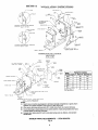
B. CLEAN THE BOILER HEATING SURFACES
At the end of heating season, clean boiler heating surfaces
thoroughly. Access to boiler firetubes may be gained by re-
moving the front and rear smokeboxes. Remove turbulators
and clean firetubes with flue brush furnished with boiler. Re-
place turbulators as shown in Figure 7. Remove soot and rust
and reseal the boiler.
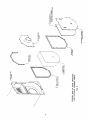
C. PROPER REMOVAL AND INSTALLATION
PROCEDURES FOR REAR REVERSING
CHAMBER LINER (See Figures 8 & 9)
Removal:
1. Remove nuts, washers and reversing chamber cover
plate.
2. Reversing chamber liner often can be removed in one
piece by inserting several fingers through the observa-
tion port opening to support the weight of the liner as
it is pulled clear of the wrapper.
3. IMPORTANT: The 2” ceramic fiber strip must be re-
placed whenever the reversing chamber liner has been
removed.
4. Remove all traces of fiber and adhesive from the rear
tube sheet. Also remove any fiber that adheres to the
front edge of the liner.
INSTALLATION:
1. Apply adhesive (i.e., waterglas) to the perimeter of rear
tube sheet and position the 2” ceramic fiber (cerafelt)
strip.
2. Ifthereversing chamber liner was removed in one piece
and is not cracked, it may be reused. If damaged, the
reversing chamber liner must be replaced. Insert the
reversing chamber liner until it is seated uniformly
against the ceramic fiber strip on the rear tube sheet.
3. IMPORTANT: The blanket on the cover plate and the
bolt hole gasket may be reused, if both are in good condi-
tion. If damaged, they must be replaced.
4. Install Cover Plate, washer and nuts. Sufficiently
tighten for gas tight seal.
(5) MAINTENANCE OF LOW WATER CUTOFF
DEVICES
IMPORTANT
PROBE AND FLOAT TYPE LOW WATER CUTOFF
DEVICES REQUIRE ANNUAL INSPECTION AND
MAINTENANCE.
A. PROBE TYPE LOW WATER CUTOFF - Although
these devices are solid state in the operation, the
probe’ is exposed to possible contamination in the
boiler water and subject to fouling.
It is important to physically remove the probe from
the boiler tapping annually and inspect that probe
for accumulation of scale or sediment.
Follow these steps to inspect, clean and/or replace
the probe:
1.
2.
3.
Ou
Turn off electric service to the boiler.
Drain boiler water to a level below the tapping
for the probe.
Disconnect wiring connections between the low
water cutoff control and the probe.
. Dismount the low water cutoff control from the
probe.
. Unscrew the probe from the boiler tapping.
. Inspect that portion of the probe that is exposed
to the boiler water for scale or sediment buildup.
. Light deposits may be removed by wiping the
probe with a damp cloth. Wiping the probe with a
cloth soaked in vinegar will remove more tena-
cious lime deposits. The most stubborn deposits
may be removed from the probe by using a diluted
amount (3 part of water to 1 part) of phosphoric
acid (H,P0,).
CAUTION — Exercise caution when handling phospho-
ric acid and follow the instruction label on its con-
tainer.
8.
9.
10.
11.
12.
13.
14.
15.
16.
17.
18.
Wire brushing of the probe is not recommended.
Clean the pipe threads of the probe to remove old,
hardened pipe dope and other foreign matter.
Apply a moderate amount of good quality pipe
dope to the pipe threads on the probe, leaving the
two end threads bare. Do not use PTFE (Teflon)
tape.
Screw the probe into the boiler tapping.
Mount the low water cutoff control on the probe.
Reconnect the control to probe wiring.
Fill the boiler to its normal waterline.
Add boiler water treatment compound as needed
(see Section III Item 8).
Restore electric service to the boiler.
Fire burner to heat the water in the boiler to drive
off free oxygen.
WARNING — BEFORE RETURNING BOILER
TO SERVICE: Follow the low water cutoff check
out procedure in Section III Item 4 Part C.
B. FLOAT TYPE LOW WATER CUTOFF - During the
heating season, if an external low water cutoff is on the
boiler, the blow off valve should be opened once a month
(use greater frequency where conditions warrant), to
flush out the sediment chamber so the device will be
free to function properly.
Low water cutoffs and water feeders should be dis-
mantled annually by qualified personnel, to the extent
necessary to insure freedom from obstructions and
proper functioning of the working parts. Inspect con-
necting lines to boiler for accumulation of mud, scale, etc.,
and clean as required. Examine all visible wiring for brittle
or worn insulation and make sure electrical contacts are clean
and that they function properly. Give special attention to sol-
der joints on bellows and float when this type of control is
used. Check float for evidence of collapse and check mercury
bulb (where applicable) for mercury separation or discolora-
tion.
DO NOT ATTEMPT TO REPAIR MECHANISMS IN THE
FIELD. Complete replacement mechanisms, including neces-
sary gaskets and installation instructions, are available from
the manufacturer.
(6) CHECK BURNER AND CONTROLS at least once a year.
See Item ® under Operating Instructions for control checks.
See Burner Manual for burner tests and adjustments.
(7) LUBRICATE BOILER COMPONENTS according to
manufacturer's instructions. Generally, this involves the burner
and circulator. This includes the type of lubricant to use, fre-
quency of lubrication, and points to lubricate.
CHECK SAFETY VALVE at the start of each heating
season and once or twice during the season to be sure it is in
working condition. To do this, fasten wire or cord to lever of
valve and pull lever standing a safe distance away from valve.
(9) GENERAL MAINTENANCE CONSIDERATIONS
A. Keep radiators and convectors clean.
B. If a hot water radiator is hot at the bottom but not at the
top, it indicates that air has accumulated inside and should
be vented. To vent radiator, hold small cup under air vent
(located near top of radiator), open vent until water escapes
and then close.
C. If much water is added to system, it is advisable to heat
system to a high temperature and vent again. This will
make less venting necessary during the winter.
D. Where an expansion tank is used, make sure that neither
the tank nor its drain pipe is exposed to freezing tempera-
tures. Never place valves in piping leading to or from ex-
pansion tank.
E. Boiler and system cleaning will help assure trouble free
operation. See Item ® & ® under Operating Instructions
for procedure.
ATTENTION TO BOILER WHILE NOT IN
OPERATION
IMPORTANT
A. IF BOILER IS NOT USED DURING WINTER TIME, IT
MUST BE FULLY DRAINED TO PREVENT FREEZE
DAMAGE.
B. STEAM BOILERS-Procedure for taking steam boilers off
line at the end of the heating season. Drain off boiler water
until it runs clear while holding the boiler temperature
between 180 to 200°F. Then refill to the top of the gauge
glass, and add necessity of adequate water treatment.
C. WATER BOILERS-Procedure for taking water boilers off
line at the end of the heating season. While the boiler tem-
perature is still between 180 to 200°F, drain water from the
bottom of the boiler until it runs clear. Then refill the sys-
tem to normal water pressure, and add necessity of adequate
water treatment.
D. Note any time raw water is introduced into the boiler it must
be immediately heated to 180°F to drive off dissolved gases. If
water treatment is used, sufficient water treatment compound
should be added to condition the make up water.
14
REPAIR PARTS
Give boiler series and model number when ordering repair
parts. All repair parts can be ordered through the commercial
steel sales office. See figures 8 and 9 for rear smokebox and
reversing chamber part descriptions.
Burnham Corporation
Commercial Steel Boilers
P.O. Box 3079
Lancaster, PA 17604
Phone: (717) 293-5846
Fax: (717) 293-5977
O O FRONT VIEW
| i
MODELS "E-20" THRU "E-40"
(48) TURBULATORS
NOTE: TUBES MARKED xX HAVE TURBULATORS.
INSTALL TURBULATORS FLUSH WITH Fig. 7
FRONT END OF TUBES.
FIRETUBE CONFIGURATION
VERSUS
TURBULATOR LOCATIONS
15
O
O
|
MODELS "E-50" THRU "E-80"
(40) TURBULATORS
|
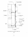
I" THK. INSULATION
+ + rc = re еннннн
h > м
5
6 |
REAR SMOKEBOX
DIVIDER PLATE
|
|
|
|
|
4 THK.X 1" WIDE ADHESIVE
FIBERGLASS TAPE GASKET
REAR SMOKEBOX
DOOR
| pero
0 |
и
LA
3 THK. CERAFELT
INSUL ATION
REVERSING
|
CHAMBER
LINER
ZZ
;
(LLL
VENT COLLAR
REAR REVERSING CHAMBER
COVER PLATE
THK.X 1% 1.0. хай 0.0.
FIBER GASKET
L
16
2" NPS CONDUIT
BUSHING
|" 3"
8 THK. X 27g DIA.
PYREX GLASS
4 THK. X I" WIDE ADHESIVE
FIBERGLASS TAPE GASKET
DOOR GUIDE
> THK. CERAFELT
INSULATION
REAR SMOKEBOX AND REVERSING CHAMBER DETAIL
Fig. 8
16
а
=
31V 1d H3A09
YIEANVHI ONISY3IA3IY
NOILYVINSNI 31VId H3A0I
HI9NYHI INISUY3IAJH г
1134V439 HL $ ,
11 0
A 0
a
400d
XO83MOWS HYAY
LC
NE
6 ‘314
SLYVd HIFWYHD DNISHIAIY ONV
,
LISTO Javi XO93MONS UVIN 10 M3IA A3001dX3
JINIT HI9NYHO9
INISHIA3Y
di¥dls 11347439 2
ЗО! „2 Хх ЭН. T
O
13MSY9 34vl
SS 1949814
ЗИ УЗ
831108 YVay
17
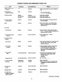
PERIODIC TESTING RECOMMENDED CHECK LIST
Pilot turndown
tests
Refractory hold in
Low-water fuel cutoff
and alarm
High limit safety
control
Operating control
Low draft, fan, air
pressure, and damper
position interlocks
As required/annually
As required/annually
Daily/weekly
Semiannually
Annually
Annually
Monthly
Service technician
Service technician
Operator
Operator
Service technician
Service technician
Operator
18
item Frequency Accomplished by Remarks
Gages, monitors, and Daily Operator Make visual inspection and record readings in
indicators log
Instrument and Daily Operator Make visual check against
equipment settings recommended specifications
Firing rate control Weekly Operator Verify factory settings
Semiannually Service technician Verify factory settings
Annually Service technician Check with combustion test
Flue, vent, stack, or Monthly Operator Make visual inspection of linkage, check for
outlet dampers proper operation
Igniter Weekly Operator Make visual inspection, check flame signal
strength If meter-fitted (see “Combustion
safety controls”)
Fuel valves
Pilot and main Weekly Operator Open limit switch — make aural and visual
check — check valve position indicators and
check fuel meters if so fitted
Pilot and main gas or Annually Service technician Perform leakage tests — refer to
main oil instructions
Combustion safety
controls
Flame failure Weekly Operator Close manual fuel supply for (1) pilot, (2) main \
fuel cock, and/or valve(s); check safety
shutdown timing; log
Flame signal Weekly Operator К flame signal meter installed, read and log;
strength for both pilot and main flames, notify
service organization if readings are very
high, very low, or fluctuating; refer to
instructions
Required after any adjustments to flame
scanner mount or pilot burner; verify
annually — refer to
instructions
See “Pilot turndown tests”
Refer to instructions
Perform a slow drain test in accordance with
ASME Boiler and Pressure Vessel Code
Section VI
Refer to instructions
Refer to instructions
Refer to instructions
re
(continued on next page)
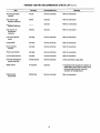
PERIODIC TESTING RECOMMENDED CHECK LIST (Cont'd)
Item Frequency Accomplished by Remarks
Atomizing air/steam Annually Service technician Refer to instructions
interlock
High and low gas Monthly Operator Refer to instructions
pressure interlocks
High and low oil Monthly Operator Refers to instructions
pressure interlocks |
High and low oil Monthly Operator Refer to instructions
temperature
interlocks
Fuel valve interlock Annually Service technician Refer to instructions
switch
Purge switch Annually Service technician Refer to instructions
Burner position Annually Service technician Refer to instructions
interlock
Rotary cup interlock Annually Service technician Refer to instructions
Low fire start interlock Annually Service technician Refer to instruclions
Automatic changeover At least annually Service technician Under supervision of gas utility
control (dual fuel)
Safety valves As required Operator In accordance with procedure in Section VI,
ASME Boller and Pressure Vessel Code,
Recommended Rules for Care and
Operation of Heating Boilers
Inspect burner Semiannualiy Service technician Refer to instructions
components
19
TN