1
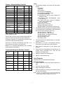
AutoDome™ System
TC700 Series Camera, Lens, Pan/Tilt,
and Receiver/Driver Modules
User’s Manual
points or short-out parts that could result in a fire or electric shock.
Never spill liquid of any kind on the unit.
IMPORTANT SAFEGUARDS
16. Servicing - Do not attempt to service this unit yourself as opening
or removing covers may expose you to dangerous voltage or other
hazards. Refer all servicing to qualified service personnel.
1. Read Instructions - All the safety and operating instructions should
be read before the unit is operated.
2. Retain Instructions - The safety and operating instructions should
be retained for future reference.
17. Damage Requiring Service - Unplug the unit from the outlet and
refer servicing to qualified service personnel under the following
conditions:
3. Heed Warnings - All warnings on the unit and in the operating
instructions should be adhered to.
a.
b.
c.
d.
4. Follow Instructions - All operating and use instructions should be
followed.
5. Cleaning - Unplug the unit from the outlet before cleaning. Do not
use liquid cleaners or aerosol cleaners. Use a damp cloth for
cleaning.
6. Attachments - Do not use attachments not recommended by the
product manufacturer as they may cause hazards.
7. Water and Moisture - Do not use this unit near water - for
example, near a bath tub, wash bowl, kitchen sink, or laundry tub,
in a wet basement, near a swimming pool, in an unprotected
outdoor installation, or any area which is classified as a wet
location.
e.
f.
When the power-supply cord or plug is damaged.
If liquid has been spilled, or objects have fallen into the unit.
If the unit has been exposed to rain or water.
If the unit does not operate normally by following the
operating instructions. Adjust only those controls that are
covered by the operating instructions, as an improper
adjustment of other controls may result in damage and will
often require extensive work by a qualified technician to
restore the unit to its normal operation.
If the unit has been dropped or the cabinet has been
damaged.
When the unit exhibits a distinct change in performance--this
indicates a need for service.
18. Replacement Parts - When replacement parts are required, be
sure the service technician has used replacement parts specified
by the manufacturer or have the same characteristics as the
original part. Unauthorized substitutions may result in fire, electric
shock or other hazards.
8. Accessories - Do not place this unit on an unstable stand, tripod,
bracket, or mount. The unit may fall, causing serious injury to a
person and serious damage to the unit. Use only with a stand,
tripod, bracket, or mount recommended by the manufacturer, or
sold with the product. Any mounting of the unit should follow the
manufacturer's instructions, and should use a mounting accessory
recommended by the manufacturer.
19. Safety Check - Upon completion of any service or repairs to this
unit, ask the service technician to perform safety checks to
determine that the unit is in proper operating condition.
An appliance and cart combination should be moved with
care. Quick stops, excessive force, and uneven surfaces
may cause the appliance and cart combination to
overturn.
20. Coax Grounding - If an outside cable system is connected to the
unit, be sure the cable system is grounded. U.S.A. models only-Section 810 of the National Electrical Code, ANSI/NFPA
No.70-1981, provides information with respect to proper
grounding of the mount and supporting structure, grounding of the
coax to a discharge unit, size of grounding conductors, location of
discharge unit, connection to grounding electrodes, and
requirements for the grounding electrode.
9. Ventilation - Openings in the enclosure, if any, are provided for
ventilation and to ensure reliable operation of the unit and to
protect it from overheating. These openings must not be blocked
or covered. This unit should not be placed in a built-in installation
unless proper ventilation is provided or the manufacturer's
instructions have been adhered to.
21. Lightning - For added protection of this unit during a lightning
storm, or when it is left unattended and unused for long periods of
time, unplug it from the wall outlet and disconnect the cable
system. This will prevent damage to the unit due to lightning and
power-line surges.
10. Power Sources - This unit should be operated only from the type
of power source indicated on the marking label. If you are not sure
of the type of power supply you plan to use, consult your
appliance dealer or local power company. For units intended to
operate from battery power, or other sources, refer to the
operating instructions.
FCC & ICES INFORMATION
11. Grounding or Polarization - This unit may be equipped with a
polarized alternating-current line plug (a plug having one blade
wider than the other). This plug will fit into the power outlet only
one way. This is a safety feature. If you are unable to insert the
plug fully into the outlet, try reversing the plug. If the plug should
still fail to fit, contact your electrician to replace your obsolete
outlet. Do not defeat the safety purpose of the polarized plug.
(U.S.A. and Canadian Models Only)
WARNING - This equipment has been tested and found to comply with
the limits for a Class B digital device, pursuant to Part 15 of the FCC
Rules and ICES-003 of Industry Canada. These limits are designed to
provide reasonable protection against harmful interference when the
equipment is operated in a residential installation. This equipment
generates, uses and can radiate radio frequency energy and, if not
installed and used in accordance with the instructions, may cause
harmful interference to radio communications. However, there is no
guarantee that interference will not occur in a particular installation. If
this equipment does cause harmful interference to radio or television
reception, which can be determined by turning the equipment off and
on, the user is encouraged to try to correct the interference by one or
more of the following measures:
Alternately, this unit may be equipped with a 3-wire groundingtype plug, a plug having a third (grounding) pin. This plug will only
fit into a grounding-type power outlet. This is a safety feature. If
you are unable to insert the plug into the outlet, contact your
electrician to replace your obsolete outlet. Do not defeat the safety
purpose of the grounding-type plug.
12. Power-Cord Protection - Power-supply cords should be routed so
that they are not likely to be walked on or pinched by items placed
upon or against them, paying particular attention to cords and
plugs, convenience receptacles, and the point where they exit
from the appliance.
-
13. Power Lines - An outdoor system should not be located in the
vicinity of overhead power lines or other electric light or power
circuits, or where it can fall into such power lines or circuits. When
installing an outdoor system, extreme care should be taken to
keep from touching such power lines or circuits as contact with
them might be fatal. U.S.A. models only - refer to the National
Electrical Code Article 820 regarding installation of CATV
systems.
-
Reorient or relocate the receiving antenna.
Increase the separation between the equipment and receiver.
Connect the equipment into an outlet on a circuit different from
that to which the receiver is connected.
Consult the dealer or an experienced radio/TV technician for help.
Intentional or unintentional changes or modifications not expressly
approved by the party responsible for compliance shall not be made.
Any such changes or modifications could void the user's authority to
operate the equipment.
The user may find the following booklet prepared by the Federal
Communications Commission helpful: "How to Identify and Resolve
Radio-TV Interference Problems". This booklet is available from the
U.S. Government Printing Office, Washington, DC 20402, Stock
No.004-000-00345-4.
14. Overloading - Do not overload outlets and extension cords as this
can result in a risk of fire or electric shock.
15. Object and Liquid Entry - Never push objects of any kind into this
unit through openings as they may touch dangerous voltage
2
Safety Precautions
Securite
CAUTION
ATTENTION
RISK OF ELECTRIC
SHOCK. DO NOT OPEN!
RISQUE DE CHOC ELECTRIQUE.
NE PAS OUVRIR.
CAUTION: TO REDUCE THE RISK OF ELECTRICAL
SHOCK, DO NOT OPEN COVERS. NO USER
SERVICEABLE PARTS INSIDE. REFER SERVICING TO
QUALIFIED SERVICE PERSONNEL.
Danger: Pour éviter tout risque d'électrocution, ne pas
ouvrir le boîtier. Il n'y a pas de pièces remplaçables à
l'intérieur. Pour toute révision, s'adresser à un technicien
spécialisé.
This label may appear on the bottom of the unit due to space
limitations.
Cet étiquette peut apparaître en dessous de l'appareil dû aux
limitations d''espace.
The lightning flash with an arrowhead symbol, within an
equilateral triangle, is intended to alert the user to the
presence of uninsulated "dangerous voltage" within the
product's enclosure that may be of sufficient magnitude to
constitute a risk of electric shock to persons.
L'éclair fléché dans un triangle équilatéral avertit l'utilisateur
de la présence d'une haute tension non isolée à l'intérieur de
l'appareil. Elle peut être d'une magnitude suffisante pour
constituer un risque d'électrocution.
Le point d'exclamation à l'intérieur d'un triangle équilatéral
avertit l'utilisateur de la présence d'instructions importantes
d'utilisation et de maintenance dans la documentation
accompagnant l'appareil.
The exclamation point within an equilateral triangle is
intended to alert the user to presence of important operating
and maintenance (servicing) instructions in the literature
accompanying the appliance.
Attention
Pour éviter un incendie ou une électrocution, ne pas exposer
les appareils qui ne sont pas conçus spécifiquement pour
usage extérieur à la pluie ou à l'humidité.
Warning
To prevent fire or shock hazard, do not expose units not
specifically designed for outdoor use to rain or moisture.
Attention: Installation should be performed by qualified
service personnel only in accordance with the National
Electrical Code or applicable local codes.
Attention: L'installation doit être effectuée uniquement par du
personnel de service qualifié conformément à la
réglementation du Code Electrique National ou à la
réglementation locale.
Power Disconnect. Units with or without ON-OFF switches
have power supplied to the unit whenever the power cord is
inserted into the power source; however, the unit is
operational only when the ON-OFF switch is in the ON
position. The power cord is the main power disconnect for all
units.
Disjonction de l'alimentation. Les appareils avec ou sans
commutateurs ON-OFF sont alimentés à chaque fois que le
cordon d'alimentation est branché à la source d'alimentation;
toutefois, les appareils disposant de commutateurs ON-OFF
ne fonctionnnent que lorsque le commutateur ON-OFF est sur
la position ON. Le cordon d'alimentation est la disjonction
d'alimentation principale pour tous les appareils.
External Power Supplies
Use only the Recommended Power Supplies. Power
supplies must comply with the requirements of the latest
version of IEC 65/VDE 0860. Substitutions may damage the
unit or cause a fire or shock hazard.
Sources d'alimentation extérieures
Utiliser
uniquement
les
sources
d'alimentation
recommandées. Les sources d'alimentation doivent être
conformes aux réglementations de la dernière version IEC
65/VDE 0860. Toute modification peut endommager l'appareil
ou provoquer un incendie ou un choc électrique.
24 VAC Units
Do Not Exceed 30 VAC Input. Voltage applied to the unit's power
input should not exceed 30 VAC. Normal input voltage is 24 VAC. User
supplied wiring from 24 VAC supply to unit must be in compliance with
electrical codes (Class 2 power levels). Do not ground 24 VAC supply
at power supply terminals or at unit's power supply terminals.
Appareils 24 VCA
Ne pas excéder 30 VCA. La tension appliquée à l'entrée d'alimentation
de l'appareil ne devrait pas excéder 30 VCA. Toute installation
électrique fournissant du 24 Volts courant alternatif doit être conforme
aux codes électriques. (Niveaux d'alimentation de la Classe 2). Ne pas
brancher une prise de terre sur les bornes d'alimentation 24 Volts ou
aux bornes d'alimentation de l'appareil.
220-240 V, 50 Hz Power Cords
220-240 V, 50 Hz power cords, input and output, must comply
with the latest versions of IEC Publication 227 or IEC
Publication 245.
Les cordons secteur 220-240 V, 50 Hz
Les cordons secteur 220-240 V, 50 Hz, entrée et sortie,
doivent êtro conformes aux versions les plus récentes de la
publication 227 de la C.I.E. ou à la publication 245 de la C.I.E.
3
Sicherheitsvorkehrungen
Precauciones de Seguridad
VORSICHT
PRECAUCION
RISIKO EINES ELEKTRISCHEN
SCHLAGES NICHT ÖFFNEN!
R IESG O D E C HOQ U E
ELEC TRICO . ¡N O ABRIR!
VORSICHT: UM EINEN ELEKTRISCHEN SCHLAG ZU
VERMEIDEN,
ABDECKUNG
NICHT
ENTFERNEN.
WARTUNGEN ALLER ART QUALIFIZIERTEM PERSONAL
ÜBERLASSEN.
Precaucion: Para Reducir El Riesgo De Choque Eléctrico,
Favor No Abrir La Cubierta. Este Equipo No Consta De
Piezas O Partes Que Requieren Servicio O Mantenimiento.
Para Reparaciones Favor Referirse A Un Técnico
Calificado.
Aus Platzgründen kann diese Warnung auf der Unterseite des Gerätes
angebracht sein.
Debido a limitaciones de espacio, esta etiqueta puede aparecer en la
parte inferior de la unidad.
Das Blitzsymbol im gleichseitigen Dreieck soll den Benutzer
auf nicht isolierte “Hochspannung” im Gehäuse aufmerksam
machen, die eventuell stark genug ist, um einen elektrischen
Schlag zu verursachen.
El símbolo representado por un relámpago con punta de
flecha dentro de un triángulo equilátero, se muestra con el
objetivo de alertar al usuario que existen "voltages
peligrosos" sin aislamiento, dentro de la cubierta de la unidad.
Dichos voltages pueden ser de tal magnitud que constituyen
un riesgo de choque eléctrico a personas.
Das Ausrufezeichen im gleichseitigen Dreieck soll den
Benutzer auf wichtige Bedienungs- und Wartungsanleitungen
in der dem Gerät beigefügten Literatur aufmerksam machen.
El símbolo de exclamación dentro de un triángulo equilátero,
se muestra con el objetivo de alertar al ususario de que
instrucciones de operación y mantenimiento importantes
acompañan al equipo.
Warnung
Um Feuer oder elektrische Schläge zu vermeiden, setzen Sie
das Gerät niemals Regen oder Feuchtigkeit aus.
Peligro
Para evitar el peligro de incendio ó choque eléctrico, no
exponga a la lluvia ó humedad, equipos que no han sido
diseñados para uso exterior.
Achtung! Die Installation sollte nur von qualifiziertem
Kundendienstpersonal
gemäß
jeweilig
zutreffender
Elektrovorschriften ausgeführt werden.
Netzanschluß. Geräte mit oder ohne Netzschalter haben
Spannung am Gerät anliegen, sobald der Netzstecker in die
Steckdose gesteckt wird. Das Gerät ist jedoch nur
betriebsbereit, wenn der Netzschalter (EIN/AUS) auf EIN
steht. Wenn man das Netzkabel aus der Steckdose zieht,
dann ist die Spannungszuführung zum Gerät vollkommen
unterbrochen.
Atención: La instalación de este equipo debe ser realizada
por personal capacitado, solo en acuerdo, y en cumplimiento
de normas del "National Electric Code" (Código Eléctrico
Nacional) ó las normas del Gobierno Nacional Local.
Para Desconectar la Alimentación: Unidades no equipadas
con interruptores ON/OFF, son alimentadas cuando el cable
de alimentación es conectado a la corriente eléctrica. Las
unidades equipadas con interruptores son alimentadas de
igual forma, pero adicionalmente requieren que el interruptor
esté posicionado en ON. El cable de alimentación es el medio
principal de desconexión del equipo.
Externe Netzgeräte
Nur vom Hersteller empfohlene Netzgeräte verwenden!
Die Netzgeräte müssen der jeweils gültigen Version der IEC
65/VDE
0860
Bestimmungen
entsprechen.
Andere
Ersatznetzgeräte können das vorliegende Gerät beschädigen
und Feuer oder Elektroschlag bewirken.
Fuentes de Alimentación Externas
Usar solo las fuentes de alimentación recomendadas. Las
fuentes de alimentación deben cumplir con los requisitos de
la versión más reciente de la IEC 65/VDE 0860. El uso de
substitutos puede dañar la unidad, ó crear peligro de incendio
o choque eléctrico.
24 VAC Geräte
Achtung! 30 Volt Eingangswechselspannung darf für 24 VAC Modelle
nicht überschritten werden. Normalbetrieb findet bei 24 Volt
Wechselspannung statt. Die Kabel- bzw. Drahtverbindung vom
Netzgerät zu dem vorliegenden Gerät muß die Bestimmungen der
Schutzklasse II erfüllen. Nicht die 24-Volt-Leitung erden weder am
Netzgerät noch an den Anschlußklemmen des vorliegenden Gerätes.
Unidades de 24 VCA
No exceder 30 VCA de entrada. Voltage suplido a la unidad no debe
exceder 30 VCA. Voltage de entrada normal es de 24 VCA. El
cableado de 24 VCA provisto por el usuario debe cumplir con las
normas eléctricas (Clase 2 de niveles de alimentación). No conectar
los 24 VCA a tierra en las terminales de la alimentación ó a las
terminales de la fuente de alimentación de la unidad.
220-240 V, 50 Hz Netzkabel, Eingang und Ausgang
220-240 V, 50 Hz Netzkabel, Eingang und Ausgang, muß die
neueste Version der IEC Vorschriften, Veröffentlichung 227
oder 245, erfüllen.
220-240 V, los cables eléctricos de 50 Hz
220-240 V, los cables eléctricos de 50 Hz, de entrada y de
salida, deben cumplir con las versiones mas recientes de la
publicación IEC 227 ó la Publicación IEC 245.
4
TC700 Series - Camera, Lens,
Pan/Tilt, and Receiver/Driver Modules
Monochrome Models
Model No.
TC750-4-1
TC750-4-2
TC750-6-1
TC750-6-2
TC750-9-1
TC750-9-2
TC750X-4-1
TC750X-4-2
TC750X-6-1
TC750X-6-2
TC750X-9-1
TC750X-9-2
ATTENTION
OBSERVE PRECAUTIONS
FOR HANDLING
ELECTROSTATIC
SENSITIVE
DEVICES
WARNING: Electrostatic-sensitive device. Use
proper CMOS/MOSFET handling precautions to
avoid electrostatic discharge.
NOTE: Grounded wrist straps must be worn and
proper ESD safety precautions observed when
handling the electrostatic-sensitive printed circuit
boards.
Sync System
EIA RS-170
EIA RS-170
EIA RS-170
EIA RS-170
EIA RS-170
EIA RS-170
CCIR
CCIR
CCIR
CCIR
CCIR
CCIR
1
Lens
4 to 40 mm
4 to 40 mm
5.8 to 58 mm
5.8 to 58 mm
8.7 to 87 mm
8.7 to 87 mm
4 to 40 mm
4 to 40 mm
5.8 to 58 mm
5.8 to 58 mm
8.7 to 87 mm
8.7 to 87 mm
Receiver
Allegiant biphase
RS-232
Allegiant biphase
RS-232
Allegiant biphase
RS-232
Allegiant biphase
RS-232
Allegiant biphase
RS-232
Allegiant biphase
RS-232
Color Models
1
Model No.
Color System Lens
Receiver
TC770-4-1
NTSC
4 to 40 mm
Allegiant biphase
TC770-4-2
NTSC
4 to 40 mm
RS-232
TC770-6-1
NTSC
5.8 to 58 mm
Allegiant biphase
TC770-6-2
NTSC
5.8 to 58 mm
RS-232
TC770-9-1
NTSC
8.7 to 87 mm
Allegiant biphase
TC770-9-2
NTSC
8.7 to 87 mm
RS-232
TC770X-4-1
PAL B
4 to 40 mm
Allegiant biphase
TC770X-4-2
PAL B
4 to 40 mm
RS-232
TC770X-6-1
PAL B
5.8 to 58 mm
Allegiant biphase
TC770X-6-2
PAL B
5.8 to 58 mm
RS-232
TC770X-9-1
PAL B
8.7 to 87 mm
Allegiant biphase
TC770X-9-2
PAL B
8.7 to 87 mm
RS-232
TC790-4-1
NTSC
4 to 40 mm
Allegiant biphase
TC790-4-2
NTSC
4 to 40 mm
RS-232
TC790-6-1
NTSC
5.8 to 58 mm
Allegiant biphase
TC790-6-2
NTSC
5.8 to 58 mm
RS-232
TC790-9-1
NTSC
8.7 to 87 mm
Allegiant biphase
TC790-9-2
NTSC
8.7 to 87 mm
RS-232
TC790X-4-1
PAL B
4 to 40 mm
Allegiant biphase
TC790X-4-2
PAL B
4 to 40 mm
RS-232
TC790X-6-1
PAL B
5.8 to 58 mm
Allegiant biphase
TC790X-6-2
PAL B
5.8 to 58 mm
RS-232
TC790X-9-1
PAL B
8.7 to 87 mm
Allegiant biphase
TC790X-9-2
PAL B
8.7 to 87 mm
RS-232
1. All models include a 1/3-inch, f/1.8, 10X auto-iris zoom lens with
auto-focus and pre-position with specified focal length.
CONTENTS
UNPACKING .................................................................. 5
TC700 Series - Camera, Lens, Pan/Tilt, and
Receiver/Driver Modules...................................... 5
SERVICE........................................................................ 5
DESCRIPTION ............................................................... 6
INSTALLATION.............................................................. 6
Removing Module From Carton ................................ 6
OPERATION .................................................................. 6
Camera Control......................................................... 6
Changing Operating Modes ...................................... 6
AutoDome Commands.............................................. 6
DIP Switches ............................................................. 8
Thumbwheel Switch .................................................. 8
Camera Commands .................................................. 8
ILLUSTRATIONS ......................................................... 11
UNPACKING
SERVICE
Unpack carefully. This is electro-mechanical equipment
and should be handled carefully. See INSTALLATION
for additional unpacking instructions.
If the unit ever needs repair service, the customer should
contact the nearest Philips Communication & Security
Systems Inc. Service Center for authorization to return
and shipping instructions.
Check for the following items:
TC700 Series: Camera, lens, pan/tilt, and
receiver/driver. See TC700 Series - Camera, Lens,
Pan/Tilt, and Receiver/Driver Modules for model
numbers.
Service Centers
U.S.A. & Canada: 800-366-2283
Mexico & Central America: 52-5-688-1466
Europe & Middle East: 44-1932-765666
South America: 54-1-956-0837
Australia: 61-2-888-9000
New Zealand: 64-4-237-7297
If an item appears to have been damaged in shipment,
replace it properly in its carton and notify the shipper. If
any items are missing, notify your Philips
Communication & Security Systems Inc. Sales
Representative or Customer Service.
The shipping carton is the safest container in which the
unit may be transported. Save it for possible future use
5
DESCRIPTION
OPERATION
The TC700 Series AutoDome™ systems are quiet,
lightweight, and discreet surveillance dome systems
containing high sensitivity 1/3-inch image format full
performance monochrome or color CCD cameras with a
10:1 auto-iris, auto-focus zoom lens, a high-speed
pan/tilt, and an intelligent, integral receiver/driver. The
one-piece camera, lens, pan/tilt, and receiver/driver
module is housed in a domed enclosure. They are
available in suspended ceiling, hard ceiling recessed,
surface, and pendant mount models. Pendant mount
models are available for indoor or outdoor applications.
Camera Control
These units, as shipped, are factory adjusted as
described below:
Line-lock mode enabled with zero degree phase
delay.
AGC on.
Backlight compensation off.
Electronic shutter off.
Automatic white balance on (color cameras only).
Changing Operating Modes
The AutoDome unit operating modes can be changed
using either a TC8135B Series Controller/Follower or an
Allegiant series keyboard. An Allegiant series keyboard
is required to take full advantage of all the various
features available. See Camera Commands for
description of various camera operating adjustments.
INSTALLATION
Attention: Installation should be performed
by qualified service personnel only in
accordance with the National Electrical Code
or applicable local codes.
AutoDome Commands
Attention: L'installation doit être effectuée
uniquement par du personnel de service
qualifié conformément à la réglementation du
Code
Electrique
National
ou
à
la
réglementation locale.
Receiver/Driver - Using Auxiliary Controls
Achtung! Die Installation sollte nur von
qualifiziertem Kundendienstpersonal gemäß
jeweilig zutreffender Elektrovorschriften ausgeführt werden.
Atención: La instalación de este equipo debe
ser realizada por personal capacitado, solo
en acuerdo, y en cumplimiento de normas
del "National Electric Code" (Código
Eléctrico Nacional) ó las normas del
Gobierno Nacional Local.
Receiver/Driver
Function
Aux
No.
Description
On/Off
Notes
Scan
1
On/off
5
Auto-Pan
2
On/off
--
Pre-Position Tour
Set Scan/auto-pan
speed
Set tour period
8
14
Auto-pan without
limits
Auto-pan between
limits
---
On/off
Inc/dec
-2
2
Auto-Speed
16
Sets pause between Inc/dec
tour callups
Enables/disables
On/off
auto-speed
15
2
Lens - Using Auxiliary Controls
Removing Module From Carton
Lens
Function
Aux
No.
Description
On/Off
Notes
Iris Control
3
--
1
Focus Control
4
--
Auto-iris ALC adj
Auto-iris Level adj
Auto-focus
Activation
Auto-iris Activation
10
11
12
--Activates AF upon
movement
Activates AI upon
movement
Auto/
manual
Auto/
manual
Peak/ave
Inc/dec
On/off
1
1
2
On/off
2
Refer to ILLUSTRATIONS for component description.
CAUTION: Keep in foil bag until grounded at
unit. Be sure to observe all safety measures
for static control when working with this unit
while out of its enclosure. Otherwise, static
damage may result.
For removal from foil bag and installation instructions,
see TC700 Series - Camera, Lens, Pan/Tilt, and
Receiver/Driver
Modules
Installation
under
INSTALLATION in the Installation and Operating
Instructions supplied with the particular Backbox
Module ordered.
13
1
Auto-Speed (AUX 16)
Auto-speed On: Issuing this command provides
variable pan speed when unit is operated from a fixed
speed location. The pan speed starts slowly and
increases as the pan control is held on. The speed
resets to slow when the pan control is released. Note:
DIP Switch S2005.4 must be in the OFF position to use
this command; see DIP Switch Settings in the applicable
Installation and Operating Instructions for additional
information.
CAUTION: Do not handle the unit by the
circuit board because this may result in
physical damage to the unit.
6
Notes:
1. The following settings are stored with pre-position
scenes:
Pan position.
Tilt position.
Zoom position.
Focus mode AUTO/MANUAL.
Focus position for MANUAL mode.
Iris mode AUTO/MANUAL.
Iris ALC/LEVEL for AUTO mode or position for
MANUAL mode.
White Balance mode AUTO/MANUAL (color
cameras only).
Red content and Blue content for MANUAL
mode (color cameras only).
Shutter mode ON/OFF.
Shutter setting for ON mode.
Backlight compensation ON/OFF.
Highlight ON/OFF (monochrome cameras only).
Camera - Using Auxiliary Controls
Camera
Function
Aux
No.
Description
On/Off
Notes
BL_COMP
20
Backlight
Compensation
On/off
1
HIGH-LIGHT
21
Highlight
On/off
1, 7
SHUTTER_ADJ
22
Shutter Adjust
Inc/dec
1
SHUTTER
23
Shutter
On/off
1
WHITE_BALANCE
30
White Balance
Auto/
manual
8
RED
31
Red Adjust
Inc/dec
1, 8
BLUE
32
Blue Adjust
Inc/dec
1, 8
R_Y_HUE
33
R-Y Hue Adjust
Inc/dec
3, 8
B_Y_HUE
34
B-Y Hue Adjust
Inc/dec
3, 8
FIXED_WB
35
Fixed
White Balance
Indoor/out 1, 8
door
FACTORY_
DEFAULTS
40
Factory Default
Settings
Set/---
1,3
LL_PHASE
41
Adjust LL Phase
Delay
Inc/dec
3
SYNC
42
Sync Mode
ll/xtal
3
AGC
43
AGC
On/off
3
Auto-iris and auto-focus revert to manual mode when the
manual iris and focus controls are used, respectively.
2. The following settings are stored as a default setting
in nonvolatile memory (EEPROM) on R/D board and
are used to restore settings at power-up:
Auto-pan left limit = 0 degrees.
Auto-pan right limit = 359.9 degrees.
Auto-pan speed = 30 degrees per second.
Auto-focus activation = ON.
Auto-iris activation = ON.
Auto-speed = OFF.
Switching to manual iris or manual focus from auto mode
reverts to the last manual setting used.
3. This setting stored as a default setting in nonvolatile
memory in camera.
Auto-focus is activated automatically upon pan or tilt
when Auto-focus Activation is on (AUX #12).
4. Pre-position #1 (if set) is automatically called-up
upon power-up just after the homing sequence.
Manual iris is activated automatically upon activating
(ON) Backlight Compensation.
5. Scan direction determined by last manual pan
direction.
Commands Using Pre-Position Controls
6. Pre-positions can be disabled such that they do not
operate during pre-position tour. They are still
available for manual call-up.
Note: Auto-pan is discontinued when the manual pan
control (joystick) is used.
Receiver/Driver
Function
PrePosition
No.
Description
SET/SHOT
Notes
Pre-position
1-60
---
Set/show
4
Future
PP Expansion
61-100
---
----/----
--
Auto-pan
left limit
101
---
Set/show
2
Auto-pan
right limit
102
---
Set/show
2
Home Position
110
---
Recalibrate/
show
--
Recording Playback:
1. Position AutoDome to the point where playback is to
start.
Disable/Enable
PP
901-960
---
Disable/
enable
6
2. Press On, AUX 100, ENTER.
Global Disable/
Enable PP
900
---
Disable/
enable
6
3. Begin controlling the AutoDome.
7. Applies to monochrome cameras only.
8. Applies to color cameras only.
Auto-Playback
Applicable only to units fitted with this feature.
4. At the completion of controlling the AutoDome, press
Off, AUX 100, ENTER.
Note: If you run out of record time prior to issuing the stop record
command, the AutoDome will position itself at the beginning and
not move until the joystick is released for one second.
7
Executing Playback:
1. Press ON, AUX 50, ENTER for continuous playback.
DIP Switch Settings
1
2
3
Off
Off
Off
On
Off
Off
Off
On
Off
On
On
Off
Off
Off
On
On
Off
On
Off
On
On
On
On
On
2. Press ON, AUX 51, ENTER for single playback.
Stopping Playback:
1. Press Off, AUX 50 or AUX 51, ENTER or move
joystick.
Resuming Playback After Stopping During Playback:
1. After stopping during playback, press On, AUX 52,
ENTER.
Maximum Speed
(°/s)
4
6
10
15
20
30
45
60
If the auto-speed feature is enabled (see DIP switch
S2005.4), these DIP switches apply only to the tilt speed.
Note: If you have moved the AutoDome since stopping, playback will
resume where playback was previously stopped.
S2005.4: This switch controls the Auto-speed feature.
When on, auto-speed is always enabled and control by
AUX 16 is ignored; see Auto-Speed (AUX 16) under
SETUP & MAINTENANCE in TC700 Series Camera,
Lens, Pan/Tilt, and Receiver/Driver Modules User’s
Manual (TC700-UM) for description. When auto-speed
is enabled, the pan speed starts out slowly and
increases as the pan control is held on. The speed
resets to slow when the pan control is released. The tilt
speed is not affected by this switch. It is still controlled by
the setting determined by DIP switches S2005.1,
S2005.2, and S2005.3. The auto-speed feature is only
applicable when the dome is being controlled by a
system generating “fixed speed” commands.
Adding To Previously Recorded Playback:
1. Execute a single playback.
2. Wait for the playback to end.
3. Press On, AUX 101, ENTER.
4. Begin controlling the AutoDome.
5. At the completion of controlling the AutoDome, press
Off, AUX 100 or AUX 101, ENTER.
Changing Ending of Previously Recorded Playback:
1. Execute a single playback.
2. Wait for the playback to reach the point where the
change is desired.
S2006.1: RS-232 Baud rate: 2400 - OFF, 9600 - ON
S2006.2: Lens Zoom Polarity
S2006.3: Lens Focus Polarity
S2006.4: Lens Iris Polarity
S2007.1: Not defined, set to OFF
S2007.2: Not defined, set to OFF
S2007.3: Not defined, set to OFF
S2007.4: Not defined, set to OFF
S2008.1: Reserved, set to OFF
S2008.2: Reserved, set to OFF
S2008.3: Reserved, set to OFF
S2008.4: Not defined, set to OFF
3. Press Off, AUX 50 or AUX 51, ENTER to stop
playback. This step is optional.
4. Press On, AUX 101, ENTER
5. Begin controlling the AutoDome.
6. At the completion of controlling the AutoDome, press
Off, AUX 100 or AUX 101, ENTER.
Erasing A Playback From Some Point
In Playback To The End:
1. Execute a single playback.
2. Wait for the playback to reach the new stopping
position.
Thumbwheel Switch
3. Press Off, AUX 50 or AUX 51, ENTER.
As Address selector, 0000 responds to all messages
regardless of address; otherwise the unit will only
respond to commands issued for that address.
4. Press Set, AUX 500, ENTER.
DIP Switches
Camera Commands
S2005.1, S2005.2, and S2005.3: These DIP switches
are used to set both the pan and tilt speeds when the
dome is being controlled by a system generating "fixedspeed" commands. The table below lists the maximum
speeds when the zoom lens is set for full wide angle.
The speed automatically decreases from the maximum
speed as the lens is adjusted towards the telephoto
settings. At its full telephoto setting, the speed will be
decreased to approximately 12% of its full wide angle
speed.
Adjustable Phase Vertical Line Lock (AUX 41)
In multicamera systems using vertical interval switchers,
it is desirable to have the video output signals from all
cameras vertically synchronized. To achieve synchronization, it may be necessary to generate phase delays
in some cameras, especially if the cameras receive
power from different phases of a 3-phase power source.
As shipped from the factory, camera vertical sync is
aligned with the positive-going zero crossing of the hot
8
side of the AC power input to the dome. This is the "zero
phase delay" position. The phase delay between the AC
line zero crossing and camera vertical sync can range to
360 degrees, with respect to the original "zero phase"
position. The 360 degree range is divided into 362 steps
for NTSC cameras and 370 steps for PAL cameras, so
that very fine adjustment of the phase delay is possible.
Backlight Compensation Off: Issuing this command
disables the camera's backlight compensation mode.
(AUX 20 - Off.)
Increase Phase Delay: Issuing this command increases
the line-lock phase delay by one step. (AUX 41 - On.)
Decrease Phase Delay: Issuing this command
decreases the line-lock phase delay by one step. The
phase delay commands have no effect when the camera
is in the internal crystal sync mode. (AUX 41 - Off.)
S929A64BE
Backlit Condition
Backlight Compensation OFF
Sync Mode Selection (AUX 42)
Line-Lock Mode On: Issuing this command puts the
camera into the line-lock sync mode. The phase delay
will be at the most recently set position. (AUX 42 - On.)
Backlight Compensation On: Issuing this command
enables the camera's backlight compensation mode.
(AUX 20 - On.)
Internal Crystal Mode On: Issuing this command puts
the camera into the internal crystal sync mode. In this
mode, the camera's vertical sync has no fixed
relationship to the AC power line. The vertical rate is
59.94 Hz for NTSC cameras and 50 Hz for PAL
cameras. (In line-lock mode, the vertical rate is 60 Hz
for NTSC cameras and 50 Hz for PAL cameras.) (AUX
42 - Off.)
AGC Mode Selection (AUX 43)
S929A66AE
The camera includes an AGC circuit that automatically
increases camera sensitivity at low levels of illumination.
Backlit Condition
Backlight Compensation ON
AGC On: Issuing this command turns the camera AGC
on. The AGC operates with its maximum range of 30 dB.
(AUX 43 - On.)
AGC Off: Issuing this command turns the camera AGC
off. The AGC operates with a fixed gain of 5 dB, resulting
in a loss of camera sensitivity, but improving the signalto-noise ratio. (AUX 43 - Off.)
line 80
line 200
Backlight Compensation (AUX 20)
Normally, the camera AGC averages the contents of the
entire field-of-view to determine the best AGC operating
point. If the field-of-view contains large brightly lit
background areas and a small dimly lit foreground
object, the camera AGC may select an operating point
that does not allow for adequate viewing of the
foreground object. The AutoDome series cameras have
a fixed zone backlight compensation mode to alleviate
this problem. With backlight compensation turned on, the
camera determines its AGC operating point by averaging
over a subset of the entire field-of-view, as shown in the
figure below. (Camera AGC must be ON for the
backlight compensation to function.) If the object of
interest falls inside this zone, its visibility will remain
relatively constant even if the background illumination
varies. To achieve the best picture quality, under most
lighting conditions, turn off the backlight compensation.
Use this mode only to specifically compensate for a
backlit condition.
S929A65AE
Zone of AGC Operation
With Backlight Compensation ON
Highlight (AUX 21)
Highlight On: Issuing this command turns on the
highlight mode. This mode is an alternative method for
compensating a field-of-view that contains a brightly lit
background and a dimly lit foreground object. With
highlight mode turned on, a fixed center zone will appear
on the screen having a gain of approximately 10 dB
higher than the operating point determined by the AGC.
The camera continues to average the contents of the
entire field-of-view to determine the best operating point.
The advantage of using this mode is that the area
surrounding the lit object will not white-wash. Only
objects in the center zone will be amplified. This mode
could also help target the backlight compensation zone
9
since both zones are the same. A dome operator can
see where the backlight compensation zone will average
in the field-of-view.
Manual White Balance - Increase Red: Issuing this
command increases the red content of the picture by
one step. (AUX 31 - On.)
Electronic Shutter (AUX 22, 23)
Manual White Balance - Decrease Red: Issuing this
command decreases the red content of the picture by
one step. (AUX 31 - Off.)
The camera's electronic shutter covers a range of 1/60
second (1/50 second for PAL units) to 1/10,000 second
in 261 steps (311 steps for PAL units). As the electronic
shutter speed increases, the time allowed during each
video field for light to collect on the CCD decreases,
resulting in a loss of sensitivity. However, higher shutter
speeds tend to produce a "stop action" effect on moving
images, greatly increasing the camera's dynamic
resolution.
Manual White Balance - Increase Blue: Issuing this
command increases the blue content of the picture by
one step. (AUX 32 - On.)
Manual White Balance - Decrease Blue: Issuing this
command decreases the blue content of the picture by
one step. (AUX 32 - Off.)
Fixed 3200 K White Balance On: Issuing this command
turns off the automatic mode, and sets the white balance
to approximately 3200 K. (AUX 35 - On.)
Increase Electronic Shutter Speed: Issuing this
command will turn on the electronic shutter, and
increase the shutter speed by one step. (AUX 22 - On.)
Fixed 5500 K White Balance On: Issuing this command
turns off the automatic mode, and sets the white balance
to approximately 5500 K. (AUX 35 - Off.)
Decrease Electronic Shutter Speed: Issuing this
command will turn on the electronic shutter, and
decrease the shutter speed by one step. (AUX 22 - Off.)
Hue Adjustment (AUX 33, 34)
Electronic Shutter Off: Issuing this command will
disable the camera's electronic shutter. (AUX 23 - Off.)
For most applications it is not necessary to make any
hue adjustments to the camera. If you do need to make
hue adjustments, be aware that by improving the color
rendition of one hue, you are probably degrading the
color rendition of some other hue. Depending on the
trade-offs required by each application, this may or may
not be acceptable.
Electronic Shutter On: Issuing this command will turn
on the camera's electronic shutter. The shutter speed
will be at the last set position. (AUX 23 - On.)
White Balance (AUX 30, 31, 32, 35)
Auto White Balance On: Issuing this command turns on
the automatic white balance. The white balance setting
adjusts continuously as the color temperature of the
scene changes. This mode is recommended for
situations where the color temperature of the scene
varies during shooting. Continuous white balancing may
not produce optimum color rendition when little or no
white is present in the scene. (AUX 30 - On.)
R-Y Hue Increase: Issuing this command will shift red
hues toward magenta by one step. (AUX 33 - On.)
R-Y Hue Decrease: Issuing this command will shift red
hues toward yellow by one step. (AUX 33 - Off.)
B-Y Hue Increase: Issuing this command will shift blue
hues toward cyan by one step. (AUX 34 - On.)
B-Y Hue Decrease: Issuing this command will shift blue
hues toward magenta by one step. (AUX 34 - Off.)
Perform "Push Button" White Balance: Take the
following steps to perform a
"push button" white
balance:
Factory Default (AUX 40)
1. Aim the camera at a white object, such as a white
wall or a piece of paper. The white object should fill
the entire field of view of the camera.
The camera can always be returned to its original state,
as shipped from the factory. (AUX 40 - On.)
Factory Defaults: Issuing this command will reset the
camera hues to their factory adjusted values, turn on the
AGC and the auto white balance, turn off the electronic
shutter and the backlight compensation, and put the
camera in line-lock mode with a phase delay of zero
degrees.
2. Issue the command (AUX 30 - Off.). The picture
should turn white within a few seconds. Continuous
automatic white balancing is now disabled.
Turning on the manual white balance disables the
automatic white balance. There are 107 steps of
adjustment for changing either the red or blue content of
the picture.
10
ILLUSTRATIONS
Site Address Thumbwheel
DIP Switches
Remove Screw &
Shipping Bracket
Prior to Operation
Tilt Motor
Remove Foam
Prior To Operation
Connector
S9407002AE
TC700 Series - Camera, Lens, Pan/Tilt, and Receiver/Driver Module
11
Patented under U.S. Patent No. 5,517,236
ALL SPECIFICATIONS SUBJECT TO CHANGE WITHOUT NOTICE. INFORMATION FURNISHED BY PHILIPS COMMUNICATION & SECURITY SYSTEMS INC. (PCSS) IS BELIEVED TO BE
ACCURATE AND RELIABLE. HOWEVER, NO RESPONSIBILITY OR LIABILITY IS ASSUMED BY PCSS FOR ITS USE, NOR FOR ANY INFRINGEMENT OF PATENTS OR OTHER RIGHTS OF
THIRD PARTIES WHICH MAY RESULT FROM ITS USE. NO LICENSE IS GRANTED BY IMPLICATION OR OTHERWISE UNDER ANY PATENT OR OTHER RIGHTS OF PCSS.
© 1994, 1995, 1996 by Philips Communication & Security Systems Inc. All Right Reserved.
BURLE ® is a registered trademark of BURLE TECHNOLOGIES, INC. Marca(s) Registrada(s).
Philips Communication & Security Systems Inc., 1004 New Holland Avenue, Lancaster, PA 17601-5606, USA Tel: 1-717-295-6123 Fax: 1-717-295-6097
Philips Communication & Security Systems Inc., 750 Vista Blvd., Suite 403, Sparks, NV 89434, USA Tel: 1-702-331-4155 Fax: 1-702-331-2306
Philips Communication & Security Systems Inc., Access Control Hardware, 7041 Orchard, Dearborn, MI 48126-1781, USA Tel: 1-313-846-2623 Fax: 1-313-846-3569
Philips Electronics UK Ltd., Windmill Court, Brooklands Close, Sunbury-on-Thames, Middlesex TW16 7DX, England, U.K. Tel: 44-1932-765666 Fax: 44-1932-783198
n.v. Philips Professional Systems s.a., Monnikenwerve 17-19, B-8000 Brugge, Belgium Tel: 32-50-454670 Fax: 32-50-454544
Philips Singapore Pte Ltd., 7500A Beach Road, #04-324 The Plaza, Singapore 199591, Republic of Singapore Tel: 65-293-0555 Fax: 65-293-7238
Printed in U.S.A./JUL96
TC700-UM00