1
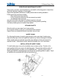
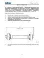
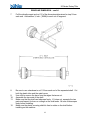
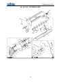
25 Series Rotary Tiller
TABLE OF CONTENTS
DESCRIPTION
PAGE
WARRANTY................................................................ 1
INTRODUCTION ......................................................... 2
SAFETY....................................................................... 3
Safety................................................................ 3
General Safety .................................................. 4
Start Up Safety.................................................. 4
Operation Safety ............................................... 4
Transport Safety................................................ 4
Service & Maintenance Safety .......................... 5
Storage Safety .................................................. 5
Safety Signs ...................................................... 5
Safety Sign Installation...................................... 5
ASSEMBLY
Assembly Instructions ....................................... 7
START UP................................................................... 7
Machine Break-In .............................................. 7
OPERATION ............................................................... 8
Pre-Operation Checklist .................................... 8
Machine Components ....................................... 9
Equipment Matching ......................................... 10
Driveline Dimension .......................................... 11
Attaching/Unhooking ......................................... 13
Field Operation.................................................. 14
Transporting ...................................................... 17
Storage ............................................................. 18
Theory of Operation .......................................... 19
MAINTENANCE .......................................................... 20
Service .............................................................. 20
Fluids and Lubricants ........................................ 20
Greasing ........................................................... 20
Servicing Intervals............................................. 21
A-Frame Adjustment ......................................... 23
Tine Replacement ............................................. 23
Shear Bolt ......................................................... 24
Slip Clutch ......................................................... 26
Troubleshooting ................................................ 27
Bolt Torque
25 Series Rotary Tiller
PARTS LISTS
Tiller Drawings and Parts List............................ 28
PTO (Shear Pin) Drawing & Parts List .............. 33
PTO (Slip Clutch) Drawing & Parts List............. 35
Gearbox Drawing & Parts List ........................... 37
SHIPPING KIT AND BUNDLE NUMBERS ................. 38
25 Series Rotary Tiller
WARRANTY POLICY
Buhler Manufacturing products are warranted for a period of twelve (12) months (90 days for
commercial application) from original date of purchase, by original purchaser, to be free from
defects in material and workmanship under correct, normal agricultural use and proper
applications.
Buhler Manufacturing’s obligations under this warranty shall be limited to the repair or
exchange, at Buhler Manufacturing’s option, of any Buhler Manufacturing product or part which
proves to be defective as provided. Buhler Manufacturing reserves the right to either inspect
the product at the buyer’s location or have it returned to the factory for inspection.
The above warranty does not extend to goods damaged or subject to accident, abuse or misuse
after shipment from Buhler Manufacturing’s factory, nor to goods altered or repaired by anyone
other than an authorized Buhler Manufacturing representative.
Buhler Manufacturing makes no Express Warranties other than those, which are specifically
described. Any description of goods, including any references and specifications in catalogues,
circulars and other written material published, is for the sole purpose of identifying goods and
shall conform to such descriptions. Any sample or model is for illustrative purposes only and
does not create an Express Warranty that the goods conform to sample or model shown.
The purchaser is solely responsible for determining suitability of goods sold. This warranty is
expressly in lieu of all other warranties expressed or implied. Buhler Manufacturing will in no
event be liable for any incidental or consequential damages whatsoever. Nor for any sum in
excess of the price received for the goods for which liability is claimed.
WARRANTY CLAIMS:
Warranty requests must be prepared on Buhler Manufacturing Warranty Claim Forms with all
requested information properly completed. Warranty Claims must be submitted within a thirty
(30) day period from date of failure repair.
WARRANTY LABOR:
Any labor subject to warranty must be authorized by Buhler Manufacturing. The labor rate for
replacing defective parts, where applicable, will be credited at 100% of the dealer’s posted shop
rate. Defective parts will receive an extra 10% discount to assist with freight or other incidental
costs.
GOVERNMENT LEGISLATION:
Warranty terms and conditions are subject to Provincial or State legislation.
IMPORTANT FACTS:
Buckets and Bucket Tines Carry No Warranty
Bent Spears Carry No Warranty
Snowblower Fan Shafts Carry No Warranty
Mower Blades Carry No Warranty
Portable Auger Parts Have Two (2) Year Warranty
Loader Parts Have Two (2) Year Warranty
IMPORTANT NOTE: This warranty does not apply to rentals
1
25 Series Rotary Tiller
INTRODUCTION
Buhler Farm King has a collection of rotary tiller models to suit your garden and
landscaping needs. The 25 Series Tiller attaches to the 3-point hitch as well as our Cat.
1 Quick Hitch and is designed to fit a variety of tractors from 12 hp to 25 hp. Tilling
widths range from 36” to 54” in the 25 Series.
The tilling shaft is equipped with four to six flanges, depending on the model. Flanges
on all series are available with four tines. This provides an optimum balance between
performance and durability, even in heavy soils and when breaking untilled soil.
Standard on all Buhler Farm King Rotary Tillers, the skid shoes are adjustable so it is
easy to set the perfect tilling depth. The automatic chain tightener is standard on all
models. This ensures the chain remains tight even under the toughest tilling conditions.
Housing within a sealed oil bath, the chain tightener is designed to be reliable and
maintenance-free. Getting close to the fences, hedges or covering a tire track is easy
with the side shift feature. The entire unit can be pushed to one side, while the PTO
shaft remains in line with the tractor to minimize stress on the universal joint. The side
shift feature is available on all 25 Series Buhler Farm King Rotary Tillers.
Keep this manual handy for frequent reference. All new operators or owners must
review the manual before using the equipment and at least annually thereafter. Contact
your Buhler Dealer if you need assistance, information, or additional copies of the
manual. Visit our website at www.buhler.com for a complete list of dealers in your area.
The directions left, right, front and rear, as mentioned throughout this manual, are as
seen facing in the direction of travel of the implement.
2
25 Series Rotary Tiller
SAFETY
Remember, YOU are the key to safety. Good safety practices not only protect you, but
also the people around you. Make these practices a working part of your safety
program. Be certain that everyone operating this equipment is familiar with the
recommended operating and maintenance procedures and follows all the safety
precautions. Most accidents can be prevented. Do not risk injury or death by ignoring
good safety practices.
The alert symbol is used throughout this manual. It indicates attention is required and
identifies hazards. Follow the recommended precautions.
The
safety alert symbol means…
ATTENTION! BECOME ALERT! YOUR SAFETY IS INVOLVED!
CAUTION
The caution symbol indicates a potentially hazardous situation that, if not avoided, may
result in minor or moderate injury. It may also be used to alert against unsafe practices.
WARNING
The Warning Symbol indicates a potentially hazardous situation that, if not avoided,
could result in death or serious injury, and includes hazards that are exposed when
guards are removed. It may also be used to alert against unsafe practices.
DANGER
The Danger Symbol indicates an imminently hazardous situation that, if not avoided will
result in death or serious injury. This signal word is to be limited to the most extreme
situations, typically for machine components that, for functional purposes, cannot be
guarded.
3
25 Series Rotary Tiller
GENERAL SAFETY
Have a first-aid kit available for use and know how to use it.
Have a fire extinguisher available, stored in a highly visible location, and know how to
use it.
Wear appropriate protective gear. This list includes but is not limited to:
- a hard hat
- Protective shoes with slip resistant soles
- Protective glasses or goggles
- Heavy gloves
- Wet weather gear
- Hearing protection
- Respirator or filter mask
Read and understand the Operator’s Manual and all safety signs before operating,
servicing, adjusting, repairing, or unplugging the equipment.
Do not attempt any unauthorized modifications to your Buhler product as this could
affect function or safety, and could affect the life of the equipment.
Never start or operate the tiller except from the operator’s station on the power unit.
Inspect and clean the working area before operating.
Keep hands, feet, clothing, and hair away from moving parts.
Ensure bystanders are clear of the area before operating.
START-UP SAFETY
Do not let inexperienced operators or children run this equipment.
Place all tractor and machine controls in neutral before starting.
Operate only with ROPS and seatbelt equipped tractors.
Do not operate inside a building unless there is adequate ventilation.
Ensure all shields are in place and in good condition before operating.
Stay clear of PTO shaft and machine when engaging PTO.
OPERATING SAFETY
Do not allow riders.
Do not wear loose fitting clothing during operation.
Never operate over 540 rpm PTO speed.
Never operate the equipment in the raised operation.
TRANSPORT SAFETY
Review Transport Safety instructions in tractor manual before moving.
Check with local authorities regarding transport on public roads. Obey all applicable
laws and regulations.
Make sure the SMV (Slow Moving Vehicle) emblem and all the lights and reflectors that
are required by the local highway and transport authorities are in place, are clean, and
can be seen clearly by all overtaking and oncoming traffic.
Never have the equipment in operation during transport.
Always travel at a safe speed.
4
25 Series Rotary Tiller
SERVICE AND MAINTENANCE SAFETY
Stop engine, set brake, remove ignition key, and wait for all moving parts to stop before
servicing, adjusting, repairing, or unplugging.
Support the equipment with blocks or safety stands before working beneath it.
Follow good shop practices including
- keep service area clean and dry
- be sure electrical outlets and tools are properly grounded
- use adequate light for the job
Use only tools, jacks, and hoists of sufficient capacity for the job.
Replace and secure all shields removed during servicing before operating.
Use heavy leather gloves to handle sharp objects.
STORAGE SAFETY
Store the unit in an area away from human activity.
Do not permit children to play on or around the stored machine.
Support frame on stands and blocks to provide a secure base.
SAFETY SIGNS
The following illustration shows the approximate location and detail of safety signs.
Keep all safety signs clean and legible and replace any that are damaged or missing.
When original parts are replaced, any safety signs affixed to those parts should be
replaced as well. Replacement safety signs are available from your local dealer.
INSTALLATION OF SAFETY SIGNS
To install safety signs, ensure the installation area is clean and dry. Decide on the
exact position before you remove the backing paper. Remove the smallest portion of
the split backing paper and align over the specified area. Carefully, press in place.
Slowly peel back the remaining paper and smooth the remaining portion in place. Small
air pockets can be pierced with a pin and smoothed out.
5
25 Series Rotary Tiller
SAFETY SIGN LOCATIONS – cont’d.
Safety sign “A”
Safety sign “B”
Safety sign “C”
Safety Sign “C”
Replace safety signs immediately should they become damaged, torn or illegible.
Obtain replacements from your authorized dealer using the part numbers shown.
6
25 Series Rotary Tiller
ASSEMBLY
The machine is shipped with the PTO shaft not installed.
To install the PTO driveline on the machine, follow this procedure:
1.
2.
3.
4.
5.
6.
Clear the area of bystanders, especially small children.
Clean the splines on the yoke and the input shaft.
Align the splines on the yoke and the shaft.
Attach the driveline to the tiller by removing the tapered pin and sliding the
yoke onto the gearbox shaft. Line up the pin with the groove in the
gearbox shaft and fasten with the tapered pin. The plastic gearbox PTO
guard has a removable door on top to access the pin. The A-frame brace
can be removed to improve accessibility. Replace the brace after
tightening the nut on the tapered pin.
Be sure the yoke is locked in position. Pull on the yoke to be sure the pin
clicks into position.
Be sure that the PTO shaft is the appropriate length for the tractor/Tiller
combination. Refer to Driveline Dimension Section for details.
START UP
MACHINE BREAK-IN
Although there are no operational restrictions on the Tiller when used for the first time, it
is recommended that the following mechanical items be checked:
A. After operating for 1/2 hour or after completing 1/2 acre:
1.
Check all nuts, bolts and other fasteners. Tighten to their specified torque
level.
2.
Check that the blades are in good condition and bolted securely to the
rotor.
3.
Check the oil level in the gearbox. Add as required.
4.
Check that the PTO driveline shield turns freely.
5.
Lubricate all grease points.
B. After operating for 5 hours and 10 hours:
1.
Repeat items 1 through 5 of Section A.
2.
Then go to the regular service schedule as defined in Section 5.
7
25 Series Rotary Tiller
PRE-OPERATION CHECKLIST
Efficient and safe operation of the Rotary Tiller requires that each operator reads and
understands the operating procedures and all related safety precautions outlined in this
section. A pre-operation checklist is provided for the operator. It is important for both
personal safety and maintaining the good mechanical condition of the Tiller that this
checklist is followed.
Before operating the machine and each time thereafter, the following areas should be
checked off:
Lubricate the machine per the schedule outlined in the Service and Maintenance
Section.
Use only a tractor of adequate power and weight to pull the machine.
Check that the machine is properly attached to the tractor. Be sure retainers are
used on the mounting pins.
Check the oil level in the gearbox. Add as required.
Check that the PTO driveline shield turns freely and that the driveline can
telescope easily. Clean and lubricate if required.
Check the blades. Be sure they are not damaged or broken and are bolted
securely to the rotor. Repair or replace as required.
Remove any entangled material on rotating parts.
Install and secure all guards, doors and covers before starting.
The four socket set screws on the inside of the PTO clutch assembly must be
turned out as far as they go to engage the clutch.
8
25 Series Rotary Tiller
OPERATION
TO THE NEW OPERATOR OR OWNER
The Buhler Farm King 25 Series Rotary Tiller is a machine that combines the primary
and secondary tillage operation into one machine. It breaks up the soil and prepares
the seed bed in one pass. Rotational power to the rotor is provided by the tractor PTO.
Be familiar with the machine before starting.
It is the responsibility of the owner or operator to read this manual and to train all
other operators before they start working with the machine. Follow all safety
instructions exactly. Safety is everyone's business. By following recommended
procedures, a safe working environment is provided for the operator, bystanders
and the area around the work site. Untrained operators are not qualified to
operate the machine.
Many features incorporated into this machine are the result of suggestions made by
customers like you. Read this manual carefully to learn how to operate the machine
safely and how to set it to provide maximum field efficiency. By following the operating
instructions in conjunction with a good maintenance program, your Tiller will provide
many years of trouble-free service.
MACHINE COMPONENTS
The Buhler Farm King 25 Series Rotary Tiller consists of a rotating drum that is
equipped with bent blades for breaking up and leveling soil. The blades are turned
through the soil while the machine moves over the working area. A Drag Shield is used
to maintain a level seedbed. Rotational power to the drum is provided by the PTO on
the tractor. The power is transmitted through the gearbox in the center of the machine
to the chain drive down the side. The A-frame can be moved to offset the machine.
A
B
C
D
E
F
G
Point A-Frame
PTO Driveline
Gear Box
Chain Drive
Rotor
Blades
Skid Plates
9
25 Series Rotary Tiller
EQUIPMENT MATCHING
To insure the safe and reliable operation of the Tiller, it is necessary to use a tractor
with the correct specifications. Use the following list as a guide in selecting a tractor to
use on the machine.
1.
Horsepower: Use Table 1 as a guide in selecting the tractor horsepower
appropriate for your width of machine. Use only small Agricultural tractors on this
machine.
Table 1 Horsepower vs. Width
Model
40S
48S
60S
Width
40 inches
(1.0m)
4 feet
(1.3m)
5 feet
(1.5m)
Horsepower
18
22
25
ALERT: Do not exceed the recommended horsepower levels. The use
of horsepower will void the warranty.
2.
3 Point Hitch:
The Tiller is equipped with a Category 1, 3 point hitch. Be sure the tractor 3 point
hitch is in the Category 1 configuration.
Install the lift arm blocks or shorten the stop chains to place the arms into the
non-sway configuration. Refer to the tractor manual for details.
3.
Load Sensing Hydraulics:
Many newer tractors are equipped with "Load Sensing" hydraulics. It is the
responsibility of the operator to set the tractor hydraulic system to provide "float"
on the 3 point hitch.
The float feature will allow the machine to follow the ground contours during
operation.
4.
PTO Shaft:
The tractor must have a 1 3/8" 6 spline 540 RPM PTO shaft to fit the driveline
shaft supplied with the machine. Do not use shaft adapters or operate at any
other speed.
It is not recommended that a tractor with variable speed PTO's be used on the
Tiller. Operating at speeds faster than 540 RPM will overload the drivetrain and
lead to early failures. Attach the safety chains supplied with the PTO shaft,
allowing sufficient slack for the Driveline during turns and operation. Check
booklet attached to the PTO for instructions.
10
25 Series Rotary Tiller
DRIVELINE DIMENSION
A PTO driveline is supplied with the machine. To accommodate the variety of 3 point
hitch geometry available today, the driveline can be too long for some machines and
must be cut. It is very important that the driveline be free to telescope but not bottom
out when going through its working range. If the driveline bottoms out, the bearings on
both the machine and tractor PTO shaft will be overloaded and fail in a short time.
When cutting the driveline, follow this procedure:
1.
2.
3.
4.
5.
6.
Clear the area of bystanders, especially small children.
Attach the Tiller to the tractor but do not attach the driveline.
Raise the machine until the input shaft is level with the tractor PTO shaft.
Measure the dimension between the locking groove on the tractor PTO shaft and
the groove on the Tiller input shaft.
Measure the same dimensions on the compressed driveline.
If the driveline dimension exceeds the machine dimension, the driveline will have
to be cut.
11
25 Series Rotary Tiller
DRIVELINE DIMENSION – cont’d.
7.
Pull the driveline apart and cut 1/2 of the dimension determined in step 5 from
each end. Add another ½ inch (12MM) to each cut off segment.
8.
Be sure to use a hacksaw to cut 1/2 from each end of the separated shaft. Cut
both the plastic tube and the metal cores.
Use a file to remove the burrs from the edges that were cut.
Assemble the two ends of the shaft.
Make sure that the shaft can telescope freely. If it does not, separate the two
parts and inspect for burrs or cuttings on the shaft ends. Be sure it telescopes
freely before installing.
Make sure the plastic covering shield is free to rotate on the shaft before
installing on the machine.
9.
10.
11.
12.
12
25 Series Rotary Tiller
ATTACHING/UNHOOKING
The Tiller should always be located on a level, dry area that is free of debris and other
foreign objects. When attaching the machine to a tractor, follow this procedure:
1.
Clear the area of bystanders, especially small children.
2.
Be sure the tractor 3 point hitch is in the Category 1 configuration and the lift
arms are in the non-sway configuration (See tractor manual).
3.
Make sure there is enough room and clearance to safely back up to the Tiller.
4.
Attach the PTO driveline to the Tiller if it was removed for storage (See
Assembly).
5.
While backing up, align the lift arm balls with the mounting pins on the Tiller.
ALERT: It may be necessary to add weight to the 3-point hitch to lower
the lift arms.
6.
Stop tractor, set park brake, remove ignition key and wait for all moving parts to
stop before dismounting.
7.
If your tractor is not equipped with a Quick Hitch:
a.
Align the left lower link arm with the mounting pin.
b.
Slide the ball over the pin and install the Linch Pin.
c.
Use the screw jack on the right lift arm to align the ball with the pin.
d.
Slide the ball over the mounting pin and install the Linch Pin.
e.
Level the frame using the screw jack.
f.
Remove retainer and pin from the mast.
g.
Align top link using the turnbuckle.
h.
Insert pin and install Linch Pin
i.
Level frame using the turnbuckle.
8.
Attach the PTO driveline:
a. Check that the driveline telescopes easily and that the shield rotates freely.
CAUTION: Be sure that the driveline does not bottom out when going
through its working angles.
b.
c.
Attach the driveline to the tractor by retracting the locking pin, slide the
yoke over the shaft and push on the yoke until the lock pin clicks into
position. Pull on the yoke to be sure it is locked in position.
Attach the anchor chain on the driveline shield to the frame.
9.
Use the 3 point hitch to raise the machine.
10.
Remove the blocks from under the Depth Gauge Shoes.
11.
Reverse the above procedure when unhooking from the tractor.
13
25 Series Rotary Tiller
FIELD OPERATION
Buhler Farm King 25 Series Rotary Tillers are designed with the inherent flexibility of
operating well in almost any kind of soil and terrain conditions. However, the operator
has the responsibility of being familiar with all operating and safety procedures and
following them.
Each operator should review this section of the manual at the start of the season and as
often as required to be familiar with the machine. When using, follow this procedure:
1.
Review and follow the pre-operation Checklist. Review Safety Instructions.
2.
Attach the tractor to the machine. See Attaching/Unhooking Section.
3.
Before going to the field review Transporting Section.
4.
Pull into the field and position the machine in a level area.
5.
Lower into working position.
6.
Set the machine:
a.
Level the frame:
Use the screw jack on the right lift arm to level the frame from side-to-side.
b.
Depth: Use the Depth Gauge Shoes on each side to set the operating
depth. Position the Depth Gauge Shoes in the top hole for shallow tilling
and in the bottom hole for deep tilling.
ALERT: In soft soil conditions, the skid plates become less effective and
sink into the ground. Use the turnbuckle on the top link to set the frame
angle so the bottom of the Depth Gauge Shoes are level when operating.
Offset:
c.
The Category Pin Brackets can be moved 3 to 4 inches along the Deck
Assembly to either side of center if required. Center the machine for
normal operation. Offset if the tire tracks are wider than the machine or
when tilling around trees, bushes or other areas.
Drag Shield:
Adjust the chain in the Adjustment Bracket to set the height of the Drag
Shield. Set the Drag Shield to just contact the tilled soil when operating.
14
25 Series Rotary Tiller
FIELD OPERATION - cont'd.
7.
Align the unit with the working area.
8.
Starting machine:
a.
Run the engine at low idle.
b.
Slowly engage the PTO control to start the machine.
c.
Slowly bring the engine to the rated PTO speed. Never exceed rated
speed.
d.
Lower the machine to the ground and proceed down the field.
9.
Stopping machine:
a.
Slowly decrease engine speed to low idle.
b.
Raise machine out of the ground.
c.
Disengage PTO clutch slowly.
CAUTION: Place all controls in neutral, lower machine, stop engine, set
park brake remove ignition key and wait for all moving parts to stop before
dismounting.
10.
Ground Speed:
Travel speed can vary between 2 and 5 mph (3 and 8 km/h) depending on the
soil and terrain conditions. It is the responsibility of the operator to note the
condition of the job being done and set the speed to obtain a quality tilling job
and maintain control of the machine.
The speed can be increased to optimize tilling.
Decrease speed if you want the soil worked to a finer texture.
11.
Operating hints:
a.
b.
c.
d.
Determine the moisture content of the soil before starting. Soil that is too
wet will "ball-up" in the rotor blades making tilling impossible. Sandy soils
normally can be worked better than heavy clay or loam soils. It is the
responsibility of the operator to determine the soil type and moisture
content before starting. It may be necessary to wait for the soil to dry out
before starting to work.
Set the length of the Top Link to obtain the quality of the job desired
without needlessly using power and fuel in churning the soil. Use the
condition of the seedbed as your guide.
When tilling hard or compacted soils, it is recommended that two passes
be used when working. Use the Depth Gauge Shoes on each side of the
frame to adjust the tilling depth of the machine. The second pass should
be made at an angle to the first to give a consistent job and minimize
compaction.
Always remove heavy crop cover, all grass and weeds, before starting to
prevent rotor plugging.
15
25 Series Rotary Tiller
FIELD OPERATION - cont'd.
e.
f.
g.
h.
The rotation of the Tines propel the machine in the forward direction.
Always use the tractor transmission to control the speed of forward travel.
Always disengage the PTO control and raise the machine out of the
ground before depressing the master clutch on the tractor.
Use low gear on the tractor to start the job. Increase the speed of forward
travel only as the quality of the job and power available will allow.
If the slip clutch slips, reduce the ground speed or raise the machine
slightly out of the ground.
16
25 Series Rotary Tiller
TRANSPORTING
When transporting the machine, review and follow these instructions:
1.
2.
3.
4.
5.
6.
7.
8.
9.
10.
Be sure all bystanders are clear of the machine.
Be sure that the machine is securely attached to the tractor and all retainer pins
are installed.
Clean the SMV emblem, lights and reflectors and be sure they are working.
Be sure you are in compliance with all applicable lighting and marking regulations
when transporting. Check with your local authorities.
Be sure your machine can clearly be seen by overtaking and oncoming traffic.
Keep to the right and yield the right-of-way to allow faster traffic to pass. Drive
on the road shoulder if permitted by law.
Do not allow riders.
Always use hazard flashers on the tractor when transporting unless prohibited by
law.
Use pilot vehicles front and rear when transporting during times of limited
visibility.
Never transport the machine faster than 20 mph (32 km/h). The ratio of the
tractor weight to the Tiller weight plays an important role in defining acceptable
travel speed. Table 2 summarizes the recommended travel speed to weight
ratio.
Table 2
Speed vs. weight Ratio
Weight of fully equipped
or loaded implement(s)
relative to weight of
towing machine
Road Speed
Up to 32 km/h
(20 mph)
1 to 1, or less
Up to 16 km/h
(10 mph)
2 to 1, or less
Do not tow
More than 2 to 1
17
25 Series Rotary Tiller
STORAGE
After the season's use, the machine should be thoroughly inspected and prepared for
storage. Repair or replace any worn or damaged components to prevent any
unnecessary down time at the start of next season. To insure a long, trouble free life,
this procedure should be followed when preparing the unit for storage:
1.
Clear the area of bystanders, especially small children.
2.
Thoroughly wash the machine using a pressure washer to remove all dirt, mud,
debris and residue.
3.
Inspect the blades and rotors for damage or entangled material. Repair or
replace damaged parts. Remove all entangled material.
4.
Change the oil in the gear box.
5.
Lubricate all grease fittings. Make sure that all grease cavities have been filled
with grease to remove any water residue from the washing.
6.
Touch up all paint nicks and scratches to prevent rusting.
7.
Move to storage area.
8.
Select an area that is dry, level and free of debris.
9.
Place blocks under the Depth Gauge Shoes.
10.
Unhook from tractor.
11.
If the machine cannot be placed inside, cover with a waterproof tarpaulin and tie
securely in place.
12.
Store the machine in an area away from human activity.
13.
Do not allow children to play on or around the stored machine.
18
25 Series Rotary Tiller
THEORY OF OPERATIONS
19
25 Series Rotary Tiller
MAINTENANCE
SERVICE
Follow Maintenance Safety Instructions as outlined.
FLUIDS AND LUBRICANTS
1.
Hydraulic Oil:
Use a standard hydraulic oil for all operating conditions.
2.
Gear Box Oil:
Use an SAE 85W90 gear oil for all operating conditions.
Gear Box Capacity: 1 U.S. quart (0.85 liter)
3.
Chain Case Grease:
Use a multi purpose grease for all operating conditions.
If chain case is removed, refill with 800 grams of grease.
4.
Storing Lubricants:
Your machine can operate at top efficiency only if clean lubricants are used. Use
clean containers to handle all lubricants. Store them in an area protected from
dust, moisture and other contaminants.
GREASING
Use a Maintenance Checklist to keep a record of all scheduled maintenance.
1.
Use a hand-held grease gun for all greasing.
2.
Wipe grease fitting with a clean cloth before greasing, to avoid injecting dirt and
grit.
3.
Replace and repair broken fittings immediately.
4.
If fittings will not take grease, remove and clean thoroughly. Also clean lubricant
passageway. Replace fitting if necessary.
20
25 Series Rotary Tiller
SERVICING INTERVALS
The periods recommended below are based on normal operating conditions. Severe or
unusual conditions may require more frequent lubrication or oil changes.
8 Hours or Daily; Telescoping Tubes and Quick Disconnect 20 Hours
1. Lubricate PTO driveline (7 locations).
ALERT: When using the safety chains supplied with the PTO shaft, the
shield bearings must be kept lubricated.
80 hours or once a season:
2. Lubricate rotor driven end
bearing (1 location)
3. Lubricate rotor drive end
bearing
(1 location).
4. Lubricate chain drive
bearing
(1 location)
-
21
use 3 squirts only
push grease in gradually
25 Series Rotary Tiller
SERVICING INTERVALS – cont’d.
40 Hours
1. Check gearbox oil level.
Add as required
2. Add approximately 10 squirts
of grease in chain case.
Annually
1. Change gearbox oil. Refill with SAE 85W90 gear oil.
2. Wash machine.
22
25 Series Rotary Tiller
MAINTENANCE
By following a careful service and maintenance program for your machine, you will
enjoy many years of trouble-free operation.
A-FRAME ADJUSTMENT
When moving the hitch along the front frame to adjust the offset, follow this procedure:
1.
Clear the area of bystanders, especially small children.
2.
Raise the machine so it is slightly out of the ground.
3.
Loosen the u-bolts through the Category Pin brackets.
4.
Slide the A-frame along the Deck until the machine is set at the desired
offset.
5.
Tighten the clamping bolts to their specified torque.
TINE REPLACEMENT
When the tines are damaged in any way, they will need to be replaced. When
replacing, follow this procedure:
1.
Clear the area of bystanders, especially small children.
2.
Raise the machine until the tines are slightly above the ground.
3.
Stop engine, set park brake, remove ignition key and wait for all moving
parts to stop before dismounting.
4.
Place blocks under each Depth Gauge Shoe to support the machine.
5.
Raise the Drag Shield and secure in the up position.
6.
Wear leather or heavy canvas gloves when handling Tines.
7.
Remove mounting bolts from Tine.
ALERT: An alternate method would be to disconnect the machine
from the tractor and tip it forward on its nose.
8.
Install a new replacement blade and tighten the mounting bolts to their
specified torque.
9.
Lower the rear gate.
10.
Remove the blocks under the skid plates.
23
25 Series Rotary Tiller
SHEAR BOLT
A shear pin is provided in the input drive shaft at the gearbox to protect the drive system
during an overload. To change the shear pin, follow this procedure:
1.
Place all controls in neutral, stop engine, set park brake, remove ignition key and
wait for all moving parts to stop before dismounting.
2.
Disconnect the PTO shaft from the tractor and lay to the side.
3.
Carefully remove remaining shear bolt using a hammer and punch if necessary.
Be careful not to enlarge the holes.
4.
Install the new shear bolt and tighten. (6mm & 40mm, Gr.5)
ALERT: Use only genuine Buhler Farm King parts. These shear bolts are
specially designed to provide protection for the drive system. Do not
install just any bolt.
SLIP CLUTCH (OPTIONAL)
During normal operation, the slip clutch can release and slip when encountering an
obstruction or when overloaded. It is designed to slip when the load exceeds 3 times its
nominal rating. When the clutch slips too frequently during normal operating conditions,
it is necessary to replace the clutch linings. NOTE: The PTO shafts are shipped with
the slip clutch disengaged. There are four socket set screws on the inside of the clutch
assembly, which are turned out as far as they go to engage the clutch. Disengage
clutch by turning set screws in fully.
To replace clutch linings, follow this procedure:
1.
Disengage the clutch by turning the four set screws all the way in.
2.
Remove the outside bolts from the clutch assembly and replace the clutch
linings.
3.
When re-tightening the bolts, stop when the clutch spacer starts to touch the
clutch plates. You should be able to just move the spacer by hand when you
have the correct bolt torque.
4.
Engage clutch by turning out set screws after assembly is complete.
24
25 Series Rotary Tiller
CLUTCH MAINTENANCE
1.
Before first use or after storage of more than one month, the clutch should be
checked.
2.
Disengage clutch by turning in the four socket set screws.
3.
Run the PTO at low idle to slip the clutch linings. This will help remove the dirt,
corrosion, and surface gloss from the clutch plates and also ensure that the
linings are loose.
4.
Engage the clutch by turning out the socket set screws.
5.
Normally the clutch will slip at a 20% higher torque after the “run in” than before.
6.
Check the temperature of the clutch after running for 20 minutes and every 8
hours after that. If the clutch is hot to the touch or smokes, check that the
outside bolts are correctly tightened as explained in slip clutch section. If clutch
still slips, linings may have to be replaced.
25
25 Series Rotary Tiller
TROUBLE SHOOTING
The Buhler Farm King 25 Series Rotary Tiller moves curved Tines on a turning rotor
through the ground to break it up and prepare a seed bed. It is a simple and reliable
system that requires minimal maintenance.
In the following section, we have listed many of the problems, causes and solutions to
the problems that you may encounter.
If you encounter a problem that is difficult to solve, even after having read through this
trouble shooting section, please call your local Buhler Farm King distributor dealer.
Before you call, please have this Operator's Manual and the serial number from your
Tiller ready.
PROBLEM
CAUSE
SOLUTION
Rotor won't
turn.
Slip clutch slipping.
Check that clutch is engaged
or replace friction plates.
PTO clutch slipping.
Set PTO clutch. See
tractor manual.
Broken drive chain.
Repair or replace chain.
****
Untilled
ground behind
machine.
3 point hitch not set.
Set 3 point hitch in
float. See tractor
manual.
Traveling too fast.
Travel slower.
Ground very hard.
Slow down. Make
2 passes.
Machine not leveled.
Adjust screw jack
on 3 point arm.
Adjust Depth Gauge
Shoes.
****
Seed bed lumpy.
Traveling too fast.
Slow down.
Make 2 passes.
****
Uneven seed bed.
Machine not level.
Level machine.
Drag Shield too high.
Adjust Drag Shield.
26
25 Series Rotary Tiller
BOLT TORQUE
27
25 Series Rotary Tiller
40”, 48” & 60” 25 SERIES TILLERS
28
25 Series Rotary Tiller
29
25 Series Rotary Tiller
PARTS LIST
WHEN ORDERING PARTS
Always give your dealer the Model, Color and Serial Number of your machine to assist
him in ordering and obtaining the correct parts. Use the exploded view and tabular
listing of the area of interest to exactly identify the required part.
40'', 48'', & 60'' 25 SERIES TILLERS
ITEM PART #
1
2
3
4
5
6
7
8
9
10
11
12
13
14
15
16
17
18
19
20
906290
906291
906292
967348
967350
959224
959225
959226
F0356
F0357
983405211
983485211
983605211
983405311
983485311
983605311
81593
912300165
903171
983005111
903319
912300131
961676
983006222
983006300
967353
983000200
983000250
967354
967355
967356
909729
909730
909731
DESCRIPTION
Deck Weldment (40")
Deck Weldment (48")
Deck Weldment (60")
Category Pin Bracket Weldment
1/2'' U-Bolt
Hex Drive Shaft (40")
Hex Drive Shaft (48")
Hex Drive Shaft (60")
PTO Shaft w/ Slip Clutch
PTO Shaft w/ Shear Pin
Drive Shaft Shield - Outer (40")
Drive Shaft Shield - Outer (48")
Drive Shaft Shield - Outer (60")
Drive Shaft Shield - Inner (40")
Drive Shaft Shield - Inner (48")
Drive Shaft Shield - Inner (60")
3/8'' Lock Washer
Gearbox PTO Guard
Spacer 1.05'' OD x 2 1/4''
Shield Mount Weldment
Drive Shaft Shield Weldment - Right
1 1/4'' - 2 Bolt Flange Bearing
1 1/4'' Bearing Only (greasable)
1 1/4'' Oil Seal Plate
Shaft Cover - Right
Bearing Cover - Left
Depth Gauge Shoe Weldment - Right
Depth Gauge Shoe Weldment - Left
Rotor Shaft Weldment (40")
Rotor Shaft Weldment (48")
Rotor Shaft Weldment (60")
Drag Shield (40")
Drag Shield (48")
Drag Shield (60")
30
25 Series Rotary Tiller
21
22
23
24
25
26
27
28
29
30
31
32
33
34
35
36
37
38
39
40
41
42
43
44
45
46
47
48
49
50
51
52
53
54
55
56
57
58
59
60
61
62
63
983000471
967357
903156
967483
967484
983000241
967386
912303405
912300172
959222
81592
967359
959223
903209
982005711
967377
912300164
967361
965911
909710
909711
909712
912301557
912303601
982006422
967363
967364
967164
906313
84299
812482
81525
84498
81627
81637
81636
81619
812763
812765
84277
812364
81701
84000
84072
812363
812026
1/4" X 11 Link Chain
Drag Shield Bracket
A-Frame Brace Plate
Tine - Right
Tine - Left
Depth Gauge Shoe Bracket
1 1/4'' Retainer Ring
1 1/4'' Oil Seal
60-B-12 Sprocket
Top Sprocket Spacer 2 1/2''OD x 13/16'' long
3/8'' Hex Nut
60-B-22 Sprocket
Bottom Sprocket Spacer 3''OD x 13/16'' long
Chain Guard
Tension Spring
Chain Tensioner Weldment
4033 B Gearbox
7/8'' x 4'' Clevis Pin
7/16" Linch Pin
Drag Shield Hinge Rod (40'')
Drag Shield Hinge Rod (48'')
Drag Shield Hinge Rod (60'')
1 5/8'' Retainer Ring
1 5/8" Oil Seal
1 5/8'' Oil Seal Plate
1 5/8'' 4-Bolt Flange Bearing
1 5/8'' Bearing only
Pound-In Grease Fitting
60H Roller Chain (55 Link w/ Connector & Offset)
5/8'' x 2'' Hex Bolt
5/8'' Lock Nut
1/4'' x 3/4'' Hex Bolt
1/4" Lock Nut
1/2'' x 3'' Hex Bolt
1/2'' Lock Washer
1/2'' Hex Nut
1/2'' x 1'' Hex Bolt
1/2'' x 1 1/2'' GR.8 Hex Bolt (NF)
1/2'' GR.8 Hex Nut (NF)
1/2'' x 1 1/2'' Hex Bolt
1/2'' Lock Nut
3/4'' Lock Washer
3/8'' B.S. Flat Washer
3/8'' x 3/4'' Hex Bolt
3/8'' Lock Nut
5/16'' x 1'' Hex Bolt
31
25 Series Rotary Tiller
64
65
66
67
68
69
70
71
72
73
74
75
76
77
78
79
80
81
82
83
81569
9812767
965807
967279
84270
984077
81620
902676
86170
903158
903159
903160
811790
81700
81568
909277
84048
9812433
982000500
912301660
5/16'' Lock Washer
1/2'' GR.8 Lock Washer
CAT. 1 Top Link Pin
Tension Spring Spacer (1 5/8'' Long)
5/8'' x 1 3/4'' Hex Bolt
1/2'' Hex Jam Nut
1/2'' x 1 1/4'' Hex Bolt
Adapter Weldment Category 1 to 0
3/8'' x 1'' Hex Bolt
A-Frame Bottom Weldment
A-Frame Top Left Hand Weldment
A-Frame Top Right Hand Weldment
3/4'' x 4 1/2'' Hex Bolt
3/4'' Hex Nut
5/16" Hex Nut
Manual Holder
1/2'' Flat Washer
1 1/2'' Cotter Pin
Side Stand Weldment
Snapper Clip
32
25 Series Rotary Tiller
25 SERIES TILLER PTO (SHEAR PIN)
33
25 Series Rotary Tiller
25 SERIES TILLER PTO PARTS LIST (SHEAR PIN)
ITEM
1
2
3
4
5
6
7
8
9
10
11
12
13
14
15
16
17
18
19
20
PART NO.
DESCRIPTION
F0357
908251
908252
907290
920-002
920-004
920-006
920-009
920-010
930-109
920-003
908245
920-013
936300
920-018
920-012
936305
920-015
966213
908244
908247
920-020
936402
Shaft Complete
Outer Half Shaft - Tractor
Inner Half Shaft w/Shear - Implement
Yoke RS
Ser 2 Repair Kit
Outer Tube Yoke
Flexible Pin
Outer Cardan Tube
Inner Cardan Tube
Flexible Pin
Inner Tube Yoke
Shear Assembly
Outer Bearing
Outer Cone Set
CM. Shield Tube (Outer)
CM. Shield Tube (Inner)
Inner Cone Set
Inner Bearing
Complete Push Button
Ball Collar Kit
Grease Zerk
Shear Pin & Nut
Safety Chain
34
25 Series Rotary Tiller
25 SERIES TILLER PTO (SLIP CLUTCH)
35
25 Series Rotary Tiller
25 SERIES TILLER PTO PARTS LIST (SLIP CLUTCH)
ITEM
1
2
3
4
5
6
7
8
9
10
11
12
13
14
15
16
17
18
19
20
21
22
23
24
25
26
*27
PART NO.
F0356
908258
936515
907290
920-002
920-004
920-006
936560
936561
930-109
920-003
936503
920-013
936300
936504
936505
936506
920-015
966213
908244
936513
936508
936340
936511
936510
936507
936402
966223
936514
936512
DESCRIPTION
Shaft Complete
Outer Half Shaft
Inner Half Shaft
Yoke
Ser 2 Repair Kit
Outer Tube Yoke
Flexible Pin
Outer Cardan Tube
Inner Cardan Tube
Flexible Pin
Inner Tube Yoke
Torque Lim, DF
Outer Bearing
Outer Cone Set
Outer Safety Tube
Inner Safety Tube
Inner Cone Set
Inner Shield Support
Complete Push Button
Ball & Collar Kit
Spring
Flange Yoke
Clutch Lining
Hub c/w Q.D.
Pressure Plate
Clutch Screw
Safety Chain
Anti-Friction Sleeve
Cover
Set Screw
* Set Screw should be backed out all the way to engage clutch
36
25 Series Rotary Tiller
25 SERIES TILLER GEARBOX
25 SERIES TILLER GEARBOX PARTS LIST
ITEM PART NO.
1
2
3
4
5
6
7
8
9
10
11
12
13
14
15
16
17
18
912300164
967300
967301
967302
967303
967304
967305
967314
967315
967316
967317
967318
967306
966542
967308
967309
967310
967312
967313
DESCRIPTION
QUANTITY
Gearbox Complete
Housing
Hex Shaft 35.2mm Diameter
Cover 110mm Diameter
Snap Ring, E.35, DIN 471/2
Snap Ring, I.72, DIN 472
Snap Ring, I.80, DIN 472
Ring, 35.2 x 44.7 x .6
Ring, 35.2 x 44.7 x .8
Ring, 35.2 x 44.7 x 1.0
Ring, 35.2 x 44.7 x .3
Ring, 35.2 x 44.7 x .4
Ball Bearing, 6010
Ball Bearing, 6207
Bearing Cone & Cup, 30207
Oil Seal, 50 x 80 x 10
Oil Seal, 35 x 72 x 10
Oil Plug, 3/8'' Ga. 2, DIN 906
Gear Set, R=1.46
1
1
1
1
1
2
2
As Required
As Required
As Required
As Required
As Required
2
1
1
2
1
3
1
37
25 Series Rotary Tiller
SHIPPING KIT AND BUNDLE NUMBERS
The following is a list of Kit Numbers for this product and the Bundle Numbers,
Descriptions and Quantities for each Kit.
QUANTITY
BUNDLE NO.
DESCRIPTION
C2540 40” Tiller c/w slip clutch PTO
1
1
F0852
F0356
Deck Assembly
PTO
C2548 48” Tiller c/w slip clutch PTO
1
1
F0853
F0356
Deck Assembly
PTO
C2560 60” Tiller c/w slip clutch PTO
1
1
F0854
F0356
Deck Assembly
PTO
C2540S 40” Tiller c/w shear pin PTO
1
1
F0852
F0357
Deck Assembly
PTO
C2548S 48” Tiller c/w shear pin PTO
1
1
F0853
F0357
Deck Assembly
PTO
C2560S 60” Tiller c/w shear pin PTO
1
1
F0854
F0357
Deck Assembly
PTO
Options:
The following is a list of options available for the Kits listed above.
902676
Adaptor kit (Cat. 1 to Cat. 0)
38
DIVISION LOCATIONS
Farm King Division
301 Mountain Street S.
Morden, MB R6M 1X7
Ph.: (204) 822-4467
Fax: (204) 822-6348
Allied/Inland Division
1260 Clarence Avenue
Winnipeg, MB R3T 1T2
Ph.: (204) 284-6100
Fax: (204) 477-2325
B.I.I. Division
1330 43rd Street N.W.
Fargo, ND 58102
Ph: (701) 282-7014
Fax: (701) 282-5865
CANADIAN WAREHOUSES
U.S. WAREHOUSES
AR, West Memphis
(870) 732-3132
GA, Stone Mountain
(770) 908-9439
ID, Meridian
(208) 887-6006
IN, Clarksville
(812) 284-3376
KS, Wichita
(316) 265-9577
MN, Lakeville
(952) 469-5267
MT, Billings
(406) 248-7771
ND, Bismarck
(701) 223-1886
ND, Fargo
(701) 282-7003
NE, Blair
(402) 426-8211
OH, Youngstown
(330) 793-0862
OR, Beaverton
(503) 641-1865
SD, Huron
(605) 352-8616
TX, Houston
(713) 928-2632
UT, Salt Lake City
(801) 972-4321
WI, Portage
(608) 742-1370
OFFSHORE WAREHOUSES
B.C., Abbotsford
(604) 864-2665
AB, Edmonton
(780) 962-6991
SK, Regina
(306) 781-2300
ON, Woodstock
(519) 539-0435
Burando Hill
Katanning
W. Australia
011-618-98-214422
Chihuahua, Mexico
011-52-158-90306
John Kerr Equipment Ltd.
Wilcoxholm Farm
Linlithgow, W. Lothian
Scotland
011-441-506-842280
Skovde, Sweden
011-46-500-452651
Naestved, Denmark
011-45-557-29511
QC, Dorion
(450) 455-4840
Buhler Manufacturing
301 Mountain Street S.
Morden MB.
R6M 1X7
Ph.: (204) 822-4467
Fax: (204) 822-6348
www.buhler.com
Printed in Canada