1
WLM2-G54
Users Guide
Warning ........................................................................................................................................................................................................................................................................................... iii
PART I
1.0
Introduction I ................................................................................................................................................................................................................................................................... 1
1.1
Summary of Features ..................................................................................................................................................................................................................................................... 1
2.0
Package Contents ........................................................................................................................................................................................................................................................... 1
3.0
System Requirements .................................................................................................................................................................................................................................................... 1
4.0
Product Views .................................................................................................................................................................................................................................................................. 1
5.0
Features ............................................................................................................................................................................................................................................................................. 3
5.1
Security Features ............................................................................................................................................................................................................................................................. 3
5.1.1
Authentication ................................................................................................................................................................................................................................................................. 3
5.1.2
Privacy ............................................................................................................................................................................................................................................................................... 3
5.1.3
Access Authorization ..................................................................................................................................................................................................................................................... 3
5.1.4
IBSS Security .................................................................................................................................................................................................................................................................... 3
5.2
Integrity Features ............................................................................................................................................................................................................................................................ 3
5.2.1
Improved Fault Tolerance .............................................................................................................................................................................................................................................. 3
5.2.2
Link Integrity .................................................................................................................................................................................................................................................................... 3
5.2.3
Spanning Tree (IEEE802.1d) ........................................................................................................................................................................................................................................... 4
5.3
Network Load Distribution Features ......................................................................................................................................................................................................................... 4
5.3.1
Load Balancing ................................................................................................................................................................................................................................................................. 4
5.3.2
Repeater ............................................................................................................................................................................................................................................................................ 4
5.3.3
WDS – Wireless Distribution System ........................................................................................................................................................................................................................ 4
5.4
Network Administration Features .............................................................................................................................................................................................................................. 4
5.4.1
SNMP – Simple Network Management Protocol .................................................................................................................................................................................................... 4
5.4.2
Syslog ................................................................................................................................................................................................................................................................................. 4
5.5
Easy Support Features ................................................................................................................................................................................................................................................... 5
6.0
Network Solutions ......................................................................................................................................................................................................................................................... 5
6.1
Typical Office Situations ................................................................................................................................................................................................................................................ 5
6.2
Apartments or Condominiums ................................................................................................................................................................................................................................... 5
6.3
Schools .............................................................................................................................................................................................................................................................................. 7
6.4
Hospitals ........................................................................................................................................................................................................................................................................... 7
6.5
Factories ............................................................................................................................................................................................................................................................................ 7
6.6
Area Intranets .................................................................................................................................................................................................................................................................. 7
7.0
Support Functions .......................................................................................................................................................................................................................................................... 7
7.1
PoE - Power over Ethernet ........................................................................................................................................................................................................................................... 7
7.2
Environmental Resistance ............................................................................................................................................................................................................................................. 8
7.3
Upgradeable Firmware .................................................................................................................................................................................................................................................. 8
7.4
Diagnostic Support ......................................................................................................................................................................................................................................................... 8
PART II
8.0
8.1
8.2
8.3
8.4
8.5
8.6
8.7
8.8
Client Configuration ...................................................................................................................................................................................................................................................... 8
Introduction II .................................................................................................................................................................................................................................................................. 8
Setup Preparation ........................................................................................................................................................................................................................................................... 8
Setup Overview ............................................................................................................................................................................................................................................................... 8
Installation of the Client Manager ............................................................................................................................................................................................................................... 8
Setup Screen .................................................................................................................................................................................................................................................................... 9
Input Parameters Through the Client Manager ..................................................................................................................................................................................................... 10
Input Parameters Through a Wired PC, Terminal Software ................................................................................................................................................................................. 10
Input Parameters Through a Wired PC, Telnet Software ..................................................................................................................................................................................... 11
PART III
9.0
9.1
9.2
9.2.1
9.2.2
9.2.3
9.2.4
9.2.5
9.3
9.4
9.4.1
Detailed Configurations .............................................................................................................................................................................................................................................. 12
Introduction III ............................................................................................................................................................................................................................................................... 12
Basic Settings .................................................................................................................................................................................................................................................................. 12
AirStation Name ........................................................................................................................................................................................................................................................... 12
Connection type ........................................................................................................................................................................................................................................................... 12
IP Address ....................................................................................................................................................................................................................................................................... 12
Default Gateway ............................................................................................................................................................................................................................................................ 12
DNS Server .................................................................................................................................................................................................................................................................... 12
Time Settings ................................................................................................................................................................................................................................................................. 13
Management ................................................................................................................................................................................................................................................................... 13
Host Setup ...................................................................................................................................................................................................................................................................... 13
i
9.4.2
9.4.3
9.5
9.5.1
9.5.2
9.5.3
9.5.4
9.5.5
9.5.6
9.5.7
9.5.8
9.6
9.6.1
9.6.2
9.6.3
9.7
9.7.1
9.7.2
9.8
9.9.1
9.9.2
9.9.3
9.10
9.10.1
9.10.2
9.10.3
9.10.4
9.10.5
9.10.6
9.10.7
9.10.8
9.10.9
9.10.10
9.11
9.11.1
9.11.2
9.11.3
9.11.4
9.11.5
9.11.6
9.12
Syslog Setup ................................................................................................................................................................................................................................................................... 13
Moved to Network Setup section ............................................................................................................................................................................................................................ 14
Bridge ............................................................................................................................................................................................................................................................................... 14
Spanning Tree ................................................................................................................................................................................................................................................................. 14
Bridge Priority ............................................................................................................................................................................................................................................................... 14
Forward Delay ............................................................................................................................................................................................................................................................... 14
“Hello” Time .................................................................................................................................................................................................................................................................. 15
Max Age ........................................................................................................................................................................................................................................................................... 15
Aging Time ...................................................................................................................................................................................................................................................................... 15
Port Priority ................................................................................................................................................................................................................................................................... 15
Path Cost ........................................................................................................................................................................................................................................................................ 15
Routing ............................................................................................................................................................................................................................................................................ 15
RIP Reception ................................................................................................................................................................................................................................................................ 15
Add Routing Table Entry .............................................................................................................................................................................................................................................. 15
Routing Table Entries .................................................................................................................................................................................................................................................... 16
Basic Filter ...................................................................................................................................................................................................................................................................... 16
Filter Settings ................................................................................................................................................................................................................................................................. 16
Basic Filter Information ............................................................................................................................................................................................................................................... 16
RADIUS ........................................................................................................................................................................................................................................................................... 16
Manual Setting ................................................................................................................................................................................................................................................................ 16
List of the Wireless PCs .............................................................................................................................................................................................................................................. 17
Authorized Wireless LAN PCs .................................................................................................................................................................................................................................. 17
Wireless .......................................................................................................................................................................................................................................................................... 17
Add Peer AirStation (MAC Address) ........................................................................................................................................................................................................................ 17
ESS-ID .............................................................................................................................................................................................................................................................................. 18
DS Channel (Wireless Channel Set) ........................................................................................................................................................................................................................ 18
MAC Restrict ................................................................................................................................................................................................................................................................. 18
EAP ................................................................................................................................................................................................................................................................................... 18
Privacy, WEP .................................................................................................................................................................................................................................................................. 19
PS - Privacy Separator .................................................................................................................................................................................................................................................. 19
BSS (Basic Service Set) Basic Rate Set ..................................................................................................................................................................................................................... 19
DTIM Period .................................................................................................................................................................................................................................................................. 19
ANY Connection .......................................................................................................................................................................................................................................................... 19
Link Integrity Settings .................................................................................................................................................................................................................................................. 19
Link Integrity .................................................................................................................................................................................................................................................................. 19
Destination Host ........................................................................................................................................................................................................................................................... 19
Interval of Checking Connection .............................................................................................................................................................................................................................. 21
Retry Count ................................................................................................................................................................................................................................................................... 21
Apply Device .................................................................................................................................................................................................................................................................. 21
Status ............................................................................................................................................................................................................................................................................... 21
Wireless Distribution System Settings .................................................................................................................................................................................................................... 21
PART IV
10.0
Diagnostics ..................................................................................................................................................................................................................................................................... 21
10.1
Introduction IV .............................................................................................................................................................................................................................................................. 21
10.2
Parameters for the Diagnostic Operation .............................................................................................................................................................................................................. 21
10.2.1 Unit Information ........................................................................................................................................................................................................................................................... 21
10.2.2 Transfer Packet Information ....................................................................................................................................................................................................................................... 21
10.2.3 Wireless LAN PC Information .................................................................................................................................................................................................................................. 21
10.2.4 Log Information ............................................................................................................................................................................................................................................................. 21
10.2.5 Ping Test ........................................................................................................................................................................................................................................................................... 22
10.2.6 Return to Default Setting ............................................................................................................................................................................................................................................ 22
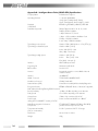
Appendix A ..................................................................................................................................................................................................................................................................................... 23
Appendix A - Intelligent Access Point (WLM2-G54) Specifications .................................................................................................................................................................................. 24
Appendix B - Troubleshooting .................................................................................................................................................................................................................................................... 25
B.1 LED Activity ............................................................................................................................................................................................................................................................................. 25
TABLE B.1 DIAG LED Activity Table ......................................................................................................................................................................................................................................... 25
B. 2 Other Problems ..................................................................................................................................................................................................................................................................... 25
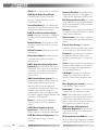
Glossary .......................................................................................................................................................................................................................................................................................... 25
Buffalo Technology Technical Support ....................................................................................................................................................................................................................................... 31
Web
.......................................................................................................................................................................................................................................................................................... 31
ii
Warning
This section explains the symbols, signs and terminology used in
this manual.
The following terminology is used in this manual to distinguish
between an Ethernet 10/100BASE-T LAN and a Wireless LAN
and should not be construed as generally accepted terminology
outside this context.
A PC with the BUFFALO Wireless client installed is called the
Wireless LAN PC.
Ethernet LAN: A LAN connected by cables
Wireless LAN: A LAN connected by radio signal
The PC used to change the AirStation access point settings:
The Setting PC.
For your safety be sure to read, understand and follow the
instructions below thoroughly before using the product. This
manual contains instructions concerning general operation of
the computer to which the product is connected in addition to
those concerning the product itself.
Please take note that our warranty will not cover any failures
and problems of the computer, any losses and failures of data,
or failures and problems of the product caused by misuse.
Signs
Strongly recommended: Follow the warning and caution
instructions issued by the PC and peripheral manufactures.
Prohibit: Do not attempt to disassemble or repair the WLML11G. This may result in fire or electric shock.
Strongly recommended: Install this product away from children.
Failure to do so may result in injury.
Prohibit: Do not handle the equipment with wet hands while it
is in operation. This may result in electric shock.
It is strongly recommended to touch a metal object such as a
door handle or metal window before touching the device in
order to prevent damage to the equipment due to static
electricity.
We strongly recommend to refer to the product manual
before and during usage of the PC and peripheral.
It is strongly recommended to remove dust from all connectors. Dust may result in failure in performance.
Do not Place this product in the following locations.
• Doing so may result in electric shock or fire, or may
adversely affect this product.
• Locations with strong magnetic fields or static electricity
(may result in failure)
• Locations prone to vibration (may result in injury or
damage)
• Locations that are not level (may result in injury or damage)
• Locations in direct sunlight (may result in failure or deformation)
• Locations close to fire, or subject to heating (may result in
failure or deformation)
• Locations with water leakage or current may result in failure
or electric shock
• Locations with excessive dust (may result in failure)
It is strongly recommended to not get caught on the cables
connected to this product. Doing so may result in personal
injury and/or damage this product.
Buffalo strongly recommends the users back up the contents of
the hard disk to other media such as floppy disks.
We recommend that dual backups before and after updating of
original data be created for important data. Data may be
damaged or lost in the following cases.
• When the device is used incorrectly
• When the device receives static electricity or electrical noise
• When the device breaks down or is repaired
• When the power is turned on immediately after the PC is
turned off
• When the device is damaged by natural disasters
Please note that BUFFALO TECHNOLOGY INC. shall not be
liable for any expenses incurred due to the damage or loss of
hard disk data that may arise in the above cases or in any other
case.
We also strongly recommend backing up the contents of the
hard disk before making any changes to your PC environment
such as installing software or installing or removing hardware.
Even if data is damaged or lost due to misuse or faults, backup
data can minimize the extent of such damage. Please note that
BUFFALO TECHNOLOGY INC. shall not be liable for any
expenses incurred due to the damage or loss of hard disk data.
iii
PART I
• Other network administrative functions
1.0
2.0
Introduction I
The WLM2-G54 protects customers’
investments over the long term. Buffalo’s new
WLAN product, WLM2-G54, is the
IEEE802.11g-based access point (AP). The
Buffalo solution offers simultaneous communication on both 11Mbps and 54Mbps bands
without annoying bottlenecks. High reliability,
manageability and standard Buffalo features
are integrated in the product and will assure
easy management and high quality signal
communication. The WLM2-G54’s versatility
will allow indoor as well as outdoor (stationto-station) applications.
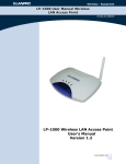
Package Contents
The AirStation™ WLM2-G54 package
consists of the following items. If any item is
missing, please contact the seller.
1. WLM2-G54 Access Point
2. AC adapter
3. Power cable
4. Mini-DIN 8 pin-Dsub 9 pin cross serial
cable
5. WLM2-G54 Manual
6. Air Navigator CD
7. Warranty and Registration card
3.0
1.1 Summary of Features
• Updated and extensive security (128-WEP,
802.1x/EAP, TKIP, RADIUS)
• Network integrity (fault tolerance, link
integrity, spanning tree)
• Network load distribution (load balancing,
repeater, WDS)
• Interoperable with IEEE802.11g Wi-Fi™‚
compliant equipment
• Roaming, best access point selection and
traffic filtering (IP and MAC address)
• ESS-ID "any" rejection option
• Configurable through web browser
• Command line setup by Telnet and/or a
serial console
• Downloadable firmware update
• Long range (diversity antenna) and even
longer range (with additional outdoor
antenna)
• Bridge to multiple networks, or AP-to-AP
communication
• Outdoor point-to-multipoint broadcasting
• Repeating function support
• Power over Ethernet, PoE, for convenient
power supply
• Auto MDI/X port for any CAT5 type
cables
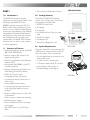
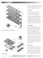
4.0 Product Views
System Requirements
The system requires IP routing externally. The
TCP/IP protocol must be loaded on each PC
used in the system. Other requirements:
• One broadband Internet connection via an
existing LAN system.
• A router, a hub or a switching hub
• UTP network cable with RJ-45 connector
• Internet Explorer 4.0 or higher, or
Netscape Navigator 4.0 or higher
TOP VIEW
BACK VIEW
Insert the antenna here.
SIDE VIEW
1
5.0
Features
The Buffalo AirStation Intelligent access point
provides the features necessary in today’s
business environment, with a high level of
reliability and security. Use of these features
along with VPN will allow the user to have
the highest security a WLAN can offer. For
minimum security measures Buffalo
recommends the use of 128bit WEP and
registering client MAC addresses in the
AirStation. Some of the noteworthy features
are shown below. Other features are listed
in Section 9.
5.1
Security Features
The WLM2-G54 model provides three levels
of security: authentication, privacy and access
authorization. The first level consists of
checking and issuing the user’s authentication
by EAP and 802.1x, similar to the Windows
XP authentication process.
The second is encrypting user’s data with
WEP, TKIP or MIC encryption algorithms.
Finally, granting the data access privilege only
after the user’s authentication is offered by
exchanging a specific key under the 802.1x
method.
5.1.1 Authentication
The IEEE802.1x security method imposes
access port control at the access point level
for each user communication signal. The EAP
function in a client PC performs an authentication login to the authorization server, such
as RADIUS, through the WLM2-G54 access
point when the link is established and before
data transmission takes place.
EAP – Extensible Authentication Protocol is
a function in a client PC, which initiates the
authentication login to a network through an
AP such as the WLM2-G54. When the client
is approved and authenticated for a communication session, the client receives a unique
WEP key from a network security server such
as RADIUS.
802.1x – Known as .1x, this is the key
exchange standard used between a client and
an AP for the user’s authentication process.
Configuration for a large network is much
easier since individual WEP settings are no
longer required for each client. In addition,
access management is performed easily in the
RADIUS server environment, making this
feature valuable for network administration.
5.1.2 Privacy
Several encryption algorithms can be used to
mix with the data for protecting privacy. WEP
is the encryption method adopted in the
current WLAN industry. Because WEP was
found to be vulnerable, WEP will be replaced
with a more powerful Advanced Encryption
System (AES) in the future so that even
higher levels of security will be available.
Meanwhile, use of TKIP and MIC can be an
alternative to AES.
WEP – Wired Equivalent Privacy is a security
method for wireless networking using the
RC4 encryption algorithm. WEP consists of
two elements: an Initialization Vector (IV) of
24 bits that describes the packet header
information, and current data of 40 or 104
bits. For example, a 128bit WEP key means a
24bit IV plus a 104bit data encryption and
they are encrypted separately.
2
TKIP – Temporal Key Integrity Protocol is an
advanced encryption method using the RC4
algorithm. Instead of using the sequential IV, a
random IV will be used, and the IV key
definition will be updated regularly at a preset
time interval.
MIC – Message Integrity Check is an
encryption method used to prevent a hacker
from changing the data content. An
encryption algorithm and bit checksum at
both the sender and receiver ends are used
to check for alteration of the packet content.
5.1.3 Access Authorization
When the client is approved and authenticated for a communication session, the client
receives a unique WEP key from the security
server, such as a RADIUS server, under the
802.1x/EAP authorization specification. A
new WEP key is issued for each connection,
thus improving security, and the WEP key is
updated regularly at a preset time interval.
Another method to screen out unauthorized
users is MAC address filtering.
ESS-ID – Extended Service Set Identification
is a type of unique identifier applied to both
the AP and the wireless client, as well as each
information packet. It allows APs to
recognize each wireless client and its traffic.
This option, however, does not provide
sufficient security for today’s wireless
networking environment. If the ESS-ID is set
to "any" or "null", anybody can connect to the
AP. Also, Windows XP automatically displays
the ESS-ID of the AP when a client receives a
"beacon." This is because APs transmit their
ESS-ID periodically and these transmissions
can be easily intercepted.
5.1.4 IBSS Security
IBSS – Independent Basic Service Set
security is used for ad hoc communications
like the point-to-point protocol (PPP)
method. WEP and MAC address filtering can
be used at this point.
5.2 Integrity Features
5.2.1 Improved Fault Tolerance
A company’s Intranet is an important
corporate communication backbone, so the
WLM2-G54 AP offers features for network
stability, which is achieved through the
system’s redundant switching function,
activated automatically in the event of faults.
The auto system redundancy provides the
network reliability necessary for mission
critical applications.
5.2.2 Link Integrity
When multiple access points use the same
frequency for roaming, they tend to interfere
with each other. The WLM2-G54 AP
automatically switches all PCs under the same
wireless ESS-ID to another available access
point if the current access point becomes
disconnected form the network, thus
preserving the connection and throughput.
MAC Address – Media Access Control
address is a hardware address that uniquely
identifies network hardware such as a
wireless NIC or an AP. It is easy to access a
network with a stolen wireless NIC.
Although it is used as the top level filtering, it
is not secure enough, because MAC
addresses can be duplicated by nonregistered users.
3
5.2.3 Spanning Tree (IEEE802.1d)
Network looping often results in repeated
packet transmission, which causes overloads
and interruption of communications. The
Spanning Tree in a network loop disconnects
one of the links, rerouting the traffic in the
5.3 Network Load Distribution
Features
5.3.1 Load Balancing
This feature enables automatic selection of an
available access point with the least load
among multiple APs. It allows easy roaming,
and the network stability can be increased
significantly through even distribution of the
traffic load.
5.3.2 Repeater
The WLM2-G54 AP can act as a repeater to
other APs. This feature provides a solution for
clients operating in the "dead zone," where
signal does not reach. Combination of this
function and add-on antennas can offer
extended range.
5.3.3 WDS – Wireless Distribution System
WDS is used to create access-point to
access-point communications when a CAT5
cable cannot be used or is unavailable. Similar
to repeating, it is primarily used to extend the
reach of the WLAN. Displaying the name of
the available AirStation while roaming is also
possible.
event of failure, avoiding packet sending
repetition and increasing network stability.
5.4 Network Administration Features
5.4.1 SNMP – Simple Network Management Protocol
The WLM2-G54 AP supports SNMP. Each
unit acts as an SNMP agent so that the
network connection status and configuration
information may be accessed remotely
through the SNMP manager, which enables
centralized traffic and fault monitoring.
5.4.2 Syslog
This feature allows sending a copy of the
system log to the Syslog server automatically.
The log contains information on the operating
status of each device, which enables real-time
monitoring of operational data, fault data, user
login data and other such information.
Although the WLM2-G54 model supports
4
the Syslog server as a part of its administrative utilities, it is possible to use additional offthe-shelf Syslog server software.
5.5
Easy Support Features
Buffalo periodically releases new firmware
updates for AirStation products. The firmware
is easily uploaded to the AirStation from a
PC. Look for new firmware releases on our
website.
6.0
Network Solutions
Some basic application scenarios are
described in this section. In each scenario
specific features of WLM2-G54 are highlighted.
6.1
Figure 5.4 Network Administration Features
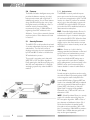
Typical Office Situations
Buffalo’s total wireless solution can provide
network connections to distant factories and
branch offices efficiently and economically.
Remote setups and remote administration
functions allow easy detection and quick
troubleshooting of network problems. The
solution works even when multiple access
points are used simultaneously. Buffalo offers
the most economical wireless building-tobuilding communication solution available.
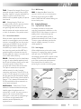
6.2
Apartments or Condominiums
Newer apartments require an Internet-ready
solution. Providing separate Internet access
to each room can be very expensive, not to
mention the high costs of initial installation.
Buffalo’s wireless solution benefits both the
landlord and the tenants. Internet access (by
a single DSL or CATV line) to the apartment
building can be shared by multiple PCs (or
rooms) anywhere in the building, a unique
feature of wireless systems. Additionally, the
Figure 5.1 Typical Office Situations
5
system can be set with authenticated security
so that only the authorized tenants can access
the network. Buffalo’s wireless solution can
be used as an optional fee-based service.
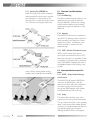
6.3
Schools
Sometimes it is necessary for students to
have personal Internet connections for
schoolwork. Wireless LANs make the
network connection flexible within a school
campus. The broadband availability area can
be expanded using Buffalo’s wireless buildingto-building solution. This solution uses an
outdoor antenna for each building instead of
installing CAT5 cable between buildings.
Accessing the network and Internet anywhere
and anytime on campus is a part of Buffalo’s
total support of educational technology.
6.4
Figure 6.2 Apartments and Condominiums
Medical test results and diagnostics for each
patient in the hospital database should be
updated in real time. The wireless solution
used to connect to the hospital network can
be crucial for saving patients’ lives. For
example, the newest diagnostic data is
updated to a hand-held wireless device at the
patient’s bedside so that the appropriate
prescription is prepared on time. Similarly,
surgical data can be transmitted to a central
database in real time for crosschecking the
operating procedures. In these cases, there is
no need for network cables. The security of
wireless communication is well enhanced by
MAC address filtering (port security) so that
only authorized personnel can access the
hospital network.
6.5
Figure 6.3 Schools
6
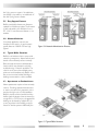
Hospitals
Factories
In this scenario, a wireless LAN is seen in a
manufacturing line in a factory. A variety of
control machines and robots are connected
to the central server and operated wirelessly.
Using Buffalo’s wireless networking system,
the manufacturing data is sent to the factory
server immediately so that the center can
efficiently respond to decisions and com-
mands. With a wireless LAN, any changes in
the factory’s machine layout can be completed quickly. Wireless flexibility offers
installation and operation cost savings for the
factory.
6.6
Area Intranets
Community buildings such as schools, city
halls, gyms, etc., can be connected by Buffalo’s
wireless LAN system to form an area
Intranet. Buffalo offers the most effective
wireless solution for building-to-building
applications. There is no need for costly and
time-consuming installations of fiber optics
and cables between buildings. Additions to
and expansion of the wireless network are
simple and flexible. Using Buffalo’s wireless
solution within the building provides
additional freedom and quick data deployment/configuration changes to network
systems.
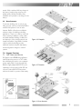
7.0
7.1
Figure 6.4 Hospitals
Support Functions
PoE - Power over Ethernet
PoE based on the IEEE802.3af specification,
draft 2.0, provides power in a CAT5 cable,
thus eliminating the need to use a separate
power supply cable. It must be used with
Buffalo’s supply adapter WLE-POE-S (sold
separately) as shown below. With PoE, the
user can locate a WLM2-G54 anywhere
without the need for a power outlet nearby.
Figure 6.5 Factories
Figure 6.6 Area Intranets
7
7.2
Environmental Resistance
The WLM2-G54 AP’s high durability design
allows resistance to environmental conditions
like temperature changes. Since it is less
susceptible to environmental change, it is
suitable for warehouses, public areas and
other locations where temperature control is
not available. Optional dust-proof and
waterproof casings are available.
Setup Preparation
With Buffalo’s firmware upgrade utility tool,
updating the firmware will be simple.
The following parameters must be known
before setting up the WLM2-G54 Intelligent
Access Point. If you do not have these, you
should consult with your IT personnel.
• WLM2-G54’s ESS-ID
• WLM2-G54’s system name or location
name
• WLM2-G54’s IP address. If you plan to use
DHCP, this is not necessary.
• WLM2-G54’s wired side MAC address.
Check the label on the back of the WLM2G54.
7.4
8.3
7.3
Upgradeable Firmware
Diagnostic Support
The WLM2-G54 provides tools to monitor
and methods to correct its wireless
operations. Some of these tools are device
status, packet status, wireless PC information,
ping test, log information and re-initialization
of parameters.
PART II
8.0
8.1
Client Configuration
Introduction II
This chapter provides general information
about:
• Basic Setup
• Time Setup
• Administrative Managing
• Bridging Setup
• Routing Setup
• Packet filtering Setup
• Limiting wireless client number
• WDS (AP-to-AP) Setup
• Wireless Setup
Explanations for each parameter and details
of how to use the parameter are described
in the next chapter. Connecting and setting
up the access point for accessing the Internet
quickly are the objective of this chapter.
8
8.2
Setup Overview
A general setup process is shown below.
Special setups for security, filtering and others
will be explained in later sections.
1. Connect the cables to WLM2-G54 based
on the wiring instructions. It is possible to
use a straight cable to connect the
AirStation directly to your PC. In this case
you need some type of Terminal Software
to set up the WLM2-G54.
2. The PC must have a valid TCP/IP setting.
For the TCP/IP setup or to check it, please
refer to the instructions for your OS (the
default IP and subnet address of the
WLM2-G54 is 1.1.1.1 and 255.255.0).
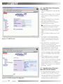
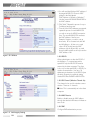
8.4 Installation of the Client Manager
1. Insert the Air Navigator CD into the CDROM drive.
2. Start the Install wizard. If the wizard does
not start, double click the Setup.exe file in
the Air Navigator CD. Install the Client
Manager.
3. Click Start and select Programs / AirStation
Utility / Client Manager to open the Client
Manager. The setup PC must have a valid
IP address of its own.
4. Select Edit / Search AirStation to look for
the nearest AirStation. Highlight the
WLM2-G54.
5. After finding an AirStation, select Admin /
Set IP address.
6. Either enter the IP and Subnet Mask
address in the boxes or select DHCP.
Figure 8.5 Setup Screen
7. Leave the Password box empty. Click OK.
8. IP address setup is complete.
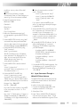
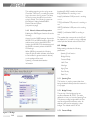
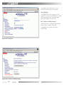
8.5 Setup Screen
1. Highlight the WLM2-G54, click the
"Admin" button, then the "Configure
AirStation" tab to open the setup screen.
In the password page, enter the following
information:
User Name: root
Password: [leave blank]
Click OK.
2. Select the language you want to use.
English and Japanese are available.
Figure 8.6.4 Security Settings
9
Figure 8.6.7 SNMP Function
Figure 8.6.9 DHCP and manual IP configuration
10
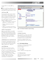
8.6 Input Parameters Through the
Client Manager
1. Click the "Management" to open the next
page.
2. Click the "Time Settings" menu on the left
(menu section) to set the current time.
Click Set.
3. Click the "LAN Setup" menu on the left;
then click the "Wireless" menu.
4. Enter appropriate ESS-ID and channel
number. (see previous page)
■ Note: ESS-IDs are case sensitive, up to
32 alphanumeric characters in length.
5. Select WEP Enable box. Enter appropriate
WEP key on line 1. Click Set. Click Set
again.
6. Click the "Network Setup" menu on the
left.
7. If you want to use the Agent Function,
check "On" and input the WLM2-G54’s
location, and Administrator Information.
Click Set.
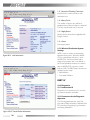
8. If the WLM2-G54 is operated in a large
network environment, using a predetermined name identification system may
be recommended, to help identify the
WLM2-G54 easily. In order to set the
name, click the "Host Setup" menu to open
the basic setup page. Type an appropriate
name in the "AirStation Name" box. Click
Set.
9. On the LAN Port page, you may opt to
obtain the IP address from the DHCP
server or enter a static IP address manually
for the access point. If you are given a
default gateway IP from your ISP, input that
address. If it is not given to you, leave the
box empty. Click Set.
8.7 Input Parameters Through a
Wired PC, Terminal Software
1. Use the serial cable provided to connect
the WLM2-G54 to the PC’s COM port.
2. Start the Hyper Terminal software included
in the Windows OS. Hyper Terminal is a
standard software in Windows but it is
3.
4.
5.
6.
7.
8.
possible to use any other off-the-shelf
software.
■ Note: If the AirStation is already
connected by Telnet or Client Manager, you
cannot log in from the terminal software.
Setup the terminal as follows:
Baud rate: 57600
Data bit: 8
Parity: None
Stop bit: 1
Flow Control: None
When the "Apxxxxxxxxxxxxx login"
prompt appears, login the WLM2-G54 by
"root".
Set the WLM2-G54’s time by using “date”
command: Setup date year/month/date
(use two digit number for the month and
the date, Example: "set date 2002/03/27")
Set the WLM2-G54’s ESS-ID by using
"essid" command.
airset 11g essid xxxxxx
(ESS-ID is defined by up to 32 alphanumeric characters. The default value is 12
digits. You can reset the ESS-ID to the
default value by using "airset 11g
essid_default" command.)
Set the WLM2-G54’s wireless channel.
Use
“airset 11g channel xx”
command. Select one number from 1~11.
The default number is 11.
Set the WLM2-G54’s WEP. Use
“airset 11g wep xxxx yyyy zzzz”
command. Xxxx is the key type (40 or
128bit) and yyyy is the key index number
and zzzz is the actual key as shown below.
Keytype: Key – 40bit WEP
Key128 – 128bit WEP
Key index: The index number of the WEP
to be used, select one from 1~4. The
default is 1.
Key: “text” + 5 blank spaces + 5 letters or
10 digits hexadecimal (for 40bit WEP) or
13 characters or 26 digits hexadecimal (for
128bit WEP)
■ Note: the text must be used with “ ”
mark.s. Examples:
airset 11g wep key text “skey5”
airset 11g wep key a3d58bb632
airset 11g wep key index 1 text
“skey5”
If you want to clear the WEP key use:
airset 11g wep keytype clear (the keytype
is explained above).
9. Set the WLM2-G54’s system ID name. Use
the “set apname xxx” command. Xxx is a
numeral of up to 32 characters. An
example is: Set apname AirStation01. If you
need to re-set the device to default name
use the following example. Set apname
_default.
10. Set the WLM2-G54’s IP address. Use “ip
address lan0 assigned_ip” command.
Assigned_ip: The IP address assigned by
your ISP. Examples:
Ip address lan0 192.168.100.60/
255.255.255.0 – manually input the
IP address and Netmask.
Ip address lan0 dhcp – use the
DHCP server
Ip address lan0 clear – clears the IP
address
11. Set the WLM2-G54’s default gateway. Use
“ip defaultgw gw_ip” command. Gw_ip is
the assigned gateway IP. Example: gw_ip
192.168.0.10
8.8 Input Parameters Through a
Wired PC,Telnet Software
The WLM2-G54 setup can be performed by
using Telnet software similar to the Terminal
software above.
In order to bring up the setup page:
1. Connect the supplied serial cable to the
AirStation and the PC’s COM port.
2. Select Start / Run.
3. Input “Telnet <WLM2-G54’s IP address>”
in the file name and press “Enter”. The IP
address can be identified through the Client
11
Manager or Terminal Software setup
screen.
4. When login prompt appears, enter “root”
as a default login name.
5. Input "?"/press "Enter" to view list of
commands.
PART III
9.0
9.1
Detailed Configurations
Introduction III
Although your AirStation will work fine in
most network environments, you may wish
to explore the advanced options. This
chapter explains each parameter in the setup
screen.
9.2
Basic Settings
Basic Settings includes the following
parameters:
AirStation Name
Connection type
IP address
Default Gateway
DNS Server
9.2.1 AirStation Name
A unique name can be set for your AirStation
in order for clients to recognize it. It identifies
each access point when multiple access points
are present. Although it is not necessary to
set this parameter, it can be useful. Once it is
set, the name will be shown at the top of the
initial setup screen.
9.2.2 Connection type
The following options are possible for the
wired LAN port setting:
10 Mbps Half Duplex
100 Mbps Half Duplex
Auto
If the port on the LAN hub is set to Full
Duplex, set the WLM2-G54 to Auto.
9.2.3 IP Address
If you do not use a DHCP server on your
network, you have to assign an IP address
manually. A specific IP address should be
obtained for this. You can use DHCP by
selecting "auto IP assignment from DHCP
Server."
9.2.4 Default Gateway
A default gateway IP should be assigned to
the AirStation. If the gateway IP is unknown,
leave the box blank. If "Auto IP assignment
from DHCP Server" is selected, the gateway
IP will be assigned automatically.
9.2.5 DNS Server
Input the IP address of the server to be used
by the WLM2-G54 for DNS resolution. If
DNS is not used, leave blank.
Figure 9.3 Time Settings
12
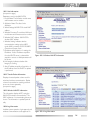
9.3
Time Settings
Input the correct time manually or input the
NTP server on your network. Using NTP
Server: Check ON box in NTP. Specify the
NTP server name, check interval, and time
zone. (see previous page)
9.4
Management
Management Settings includes the following
parameters:
Host Setup
Time Settings
Syslog Setup
Unit Information
Transfer Packet Information
Wireless LAN PC Information
Log Information
Ping Test
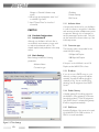
Figure 9.4.1 Host Setup
Firmwave Update
Return to Default Setting
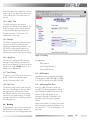
9.4.1 Host Setup
The user ID is "root". The default password is
blank -- no password.
To input a new password:
• Enter the password in the "New Password"
field
• Re-enter the password in the "Confirm
Password" field
If you are changing an old password, you must
enter the old password in the "Current
Password" field also.
Configuration of the WLM2-G54 via a web
browser (including Client Manager) or a
Telnet session may be enabled or disabled
here. A wired session via the serial port and
terminal software may be used to configure
the WLM2-G54 if WEB and Telnet are
disabled.
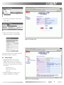
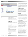
9.4.2 Syslog Setup
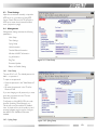
Figure 9.4.2 Syslog Setup
13
This enables reporting to the syslog server.
Check the "ON" box if you want the system
logs to be sent to the log server. The setup
for the log server should be found in the
syslog’s manual. The following log type can
be tranfered: Setting, Autheutification,
Device, Filter, and System.
(see previous page)
Interfaces(2)=PHY interface information
IP(4)=Whether IP is working or not.
Icmp(5)=Whether ICMP protocol is working
or not.
TCP(6)=Whether TCP protocol is working or
not.
9.4.3 Moved to Network Setup section
UDP(7)=Whether UDP protocol is working
or not.
Enabling the SNMP agent function allows the
following:
SNMP(11)=Whether SNMP is working or
not.
Access from the SNMP manager. Access the
WLM2-G54 local MIB information (through a
web browser) such as the WLM2-G54’s
location, the WLM2-G54’s administrator, and
the SNMP community where the WLM2G54 belongs.
The number that corresponds to the ID will
be displayed. If you want to assign a different
value, input the desired value and click "Set."
When MIB file is accessed, the following
object ID (the ID which indicates information
to be included in general network devices)
or the number will be used.
System(1)=General administrative
information
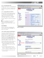
9.5
Bridge
Bridge settings includes the following
parameters:
Spanning Tree Function
Bridge Priority
Forward Delay
Hello Time
Max Age
Aging Time
Port Priority
Path Cost
9.5.1 Spanning Tree
This function is used to prevent data from
being circulated infinitely when the network is
a loop type.
9.5.2 Bridge Priority
The priority of the bridge can be set
anywhere between 0~65535. The value
depends on how you form the Spanning Tree.
The primary routing bridge within the Tree
must be assigned the minimum value. An
arbitrary value can be assigned to other
bridges. The default value is 32768.
9.5.3 Forward Delay
Figure 9.5 Bridge
14
Data forwarding can be delayed by a preset
length of time. The delay time value may be
from 4~30 seconds. The default value is 5
seconds.
9.5.4 “Hello” Time
The Hello message (to the network)
broadcast time interval can be changed. The
"Hello" message is used to set up network
routing under the Spanning Tree protocol.
The interval can be 1~10 seconds. The
default value is 2 seconds.
9.5.5 Max Age
The "Hello" message time out period can be
changed. The time out period starts the
spanning tree elapse timing calculation once
the "Hello" message signal reception has
ceased. Once the Max Age time period is
exhausted, the network topology will change.
Figure 9.6 Routing
9.5.6 Aging Time
Self-learned or registered MAC addresses
that are not active will be erased after the
Aging Time has elapsed. The value can be set
anywhere from 10~1000000 seconds. The
default value is 300 seconds.
are supported:
9.5.7 Port Priority
9.6.1 RIP Reception
The priority of the STP port can be set from
0~255. Smaller values will have higher
priority. The default value is 128.
The RIP information received by the WLM2G54 can be set to RIP1, RIP2, RIP1 and RIP2,
or no RIP. The default is both RIP1 and RIP2.
9.5.8 Path Cost
9.6.2 Add Routing Table Entry
The primary bridge owns a lower cost than
the cost to other bridges so that the “Hello”
message issued from the primary bridge
automatically adds the cost to the message
received from its parent bridge. The “Hello”
message issued from a route bridge has 0 as
the route path cost.
Routing (or RIP) information can be set
manually. The following parameters will be
used. Destination address=The network IP
address and the subnet mask for the
destination. Gateway=The packet to the
destination passes through the gateway
address.
9.6
Metric=total number of routers to be passed
before the packet reaches its destination. You
can select from 1~15. The default value is 15.
click “Add.”
Routing
Communication routing can be set between
WLM2-G54 and other network devices in
the same network. The following parameters
RIP reception
Add Routing Table Entry
Routing Table Entries
15
Changes to the parameters (DHCP, DNS,
etc.) are locked out. If you make a mistake
here and “lock yourself out,” the WLM2G54 can be returned to the factory default
settings (ALL of them!) by holding down
the INIT button on the back of the unit for
3 seconds.
9.7.2 Basic Filter Information
Displays the current settings. To change a
setting, check the box on the item to be
changed and click "delete the checked rules."
The setting can be reset to the default by
clicking "Initialize Rule."
9.8
Figure 9.7 Basic Filter
9.6.3 Routing Table Entries
Set routing information recognition and
elimination. Check the item to be eliminated;
then click "Delete Checked Items."
9.7
Basic Filter
This is a simple filter for limiting access to the
WLM2-G54.
9.7.1 Filter Settings
Four filters can be enabled by clicking “add
the rule.” They are:
• A setup from a wireless LAN is forbidden.
This will prohibit access to the WLM2G54’s configuration screen from a wireless
client.
• A setup from a wired LAN is forbidden.
This will disable access to the configuration screens from a wired LAN PC.
• A setup over an AP is forbidden. This
keeps anyone who is actually connected to
a DIFFERENT AP from configuring the
WLM2-G54.
• A request from a WLAN is ignored.
16
RADIUS
Set up RADIUS parameters. When a client
requests communication with the WLM2-G54
access point, the WLM2-G54 reports its own
MAC address to the RADIUS server and asks
for communication approval to the client.
Once the client is recognized by the RADIUS,
the RADIUS issues a key to the AP as well as
the client for initiation of communications.
Server Name=The name of the RADIUS
server or the IP address.
Port Number=The port number to be used
at the RADIUS upon approval. Some systems
use 1645 as the default port number.
Shared Secret=The secret key to be used
between the WLM2-G54 and the client. It is
the same key used between the RADIUS
server and the AP for communication. Use
numeral characters between 1~255.
(see next page)
9.9.1 Manual Setting
MAC addresses may be added to the
authorized list manually. If RADIUS is enabled,
the user must first be authenticated. Enter
the MAC address in the "MAC address of
wireless LAN PC" field and click "add." The
MAC address must be in two-digit groups
separated by colons. For example,
00:40:26:00:11:22. (see next page)
9.9.2 List of the Wireless PCs
Displays the PCs that are communicating with
the WLM2-G54. Check the "registration" box
and click the "change" button to add a MAC
address.
9.9.3 Authorized Wireless LAN PCs
Displays all MAC addresses that are allowed
to communicate with the WLM2-G54. The
status shows the current active MAC
addresses on the network. To eliminate a
specific MAC address from the network,
check the "delete" box and click the "change"
button.
■ Note: If configuring from a wireless PC,
add your MAC address to the list of
authorized wireless LAN PCs (MAC restrict
screen).
9.10 Wireless
Wireless communication parameters and
how to use them under the "IEEE802.11g"
page. (see next page)
Figure 9.8 RADIUS
9.10.1 Add Peer AirStation (MAC Address)
The wireless LAN MAC addresses of all
AirStations that will be communicating with
each other have to be registered in each
AirStation. Up to 6 AirStations can be
registered in one AP. Input the MAC address
in the two-digit format (00:40:26:00:11:22).
Click "add" to register the MAC address. The
added MAC address is checked in the
"wireless MAC address" under the Diagnostic
screen, on the Device Information page.
1. Open the Configuration Screen of the
primary WLM2-G54, and go to the LAN
Settings screen
2. The User Name should be "root", and
there is no password unless you have set
one up on a previous configuration session.
3. Click on the WDS link at the bottom left
side of the screen.
Figure 9.9.1 Manual Setting
17
4. You will need the Wireless MAC address of
the target WLM2-G54. Enter its MAC
address in the field labeled
"MAC Address of AirStation (Wireless)."
Use the format XX:XX:XX:XX:XX:XX for
the MAC address.
5. Click "Add." Repeat this process for up to
5 additional access points.
6. Once all of the MAC addresses are entered,
repeat this process for each WLM2-G54
you wish to set up for AP-AP communications. The second WLM2-G54 must have
the MAC address of the first one.
Example: Suppose you wish to set up
three units, #1 as a central unit, with #2
and #3 talking to #1, but not to each
other. AP #1 would have the MAC
addresses of both #2 and #3, as noted
above, but #2 and #3 would only have the
MAC address of #1.
Figure 9.10 Wireless
9.10.2 ESS-ID
Allows administrator to alter the ESS-ID of
the AirStation. To communicate with a
specific AP only, the AP’s ESS-ID must be
entered in the client computer. The client
looks only for that specific AP (or ESS-ID) for
wireless communication. Use up to 32
alphanumeric characters for the ESS-ID (case
sensitive). Roaming is possible by setting
identical ESS-IDs and WEP in WLM2-G54s.
9.10.3 DS Channel (Wireless Channel Set)
The channel to be used for wireless communication. There are 11 channels.
■ Note: This is automatically set in the client
computer.
9.10.4 MAC Restrict
Enable or disable access by MAC address
through the wireless LAN network infrastructure mode.
9.10.5 EAP
Configure EAP authentication process.
Figure 9.11 Link Integrity Settings
18
Configure EAP in the Security/802.11g
screen.
■ Note: For MAC Access Restriction, do not
check the "Enable" box until you have set up
Authorized MAC addresses (Section 9.8.4.3).
9.10.6 Privacy, WEP
Set the encryption method used in wireless
communications for the protection of your
data. It is necessary that the WEP key match
between two parties for secure communications. If multiple keys are used, the order
must match between communicating devices.
Examples of WEP key input are:
• 5 digits of ASCII characters. They are case
sensitive and “_” is allowed, i.e. Skey5.
• 10 digits of hexadecimal numbers, i.e.
a3d58b62fe.
• If WEP is not used, leave the box blank or
input all 0s, which is equivalent to no-WEP.
Figure 9.12 Wireless Distribution System Settings
9.10.7 PS - Privacy Separator
Enables automatic selection of the WLM2G54 with the least load within the roaming
area. If PS is used, communications between
wireless clients will be automatically blocked.
All clients are forced to go through the
WLM2-G54 and the system’s combined
security measures.
9.10.8 BSS (Basic Service Set) Basic Rate Set
The transmission data rate between devices.
If one device supports 2Mbps only, the data
rate for the entire network will be limited to
2Mbps. Otherwise, use 11Mbps max.
9.10.9 DTIM Period
WLM2-G54 transmits beacon signals to
nearby clients in the preset interval. Once
this option is used in the AP, the client must
set the power management of the client card
in order to control the beacon interval.
Select a number from 1~255 sec. Selection
of a larger number may save energy
consumption, but it may delay wireless
communication. The default value 1
recommended.
9.10.10 ANY Connection
Allows a client PC to connect to the nearest
WLM2-G54 by manually entering the word
"any" for the ESS-ID in the Client Manager. If
the "ANY Connection" is deselected in the
WLM2-G54, the WLM2-G54 will not be
found using the ESS-ID of "any" in the client
PC.
9.11 Link Integrity Settings
Link Integrity is a rerouting feature activated
when the wired connection is lost.
(see previous page)
9.11.1 Link Integrity
Enable or disable the Link Integrity feature.
9.11.2 Destination Host
Specify a host server name to which the
WLM2-G54 sends packets to confirm
connection.
19
9.11.3 Interval of Checking Connection
Interval timer to check connection with
destination host.
9.11.4 Retry Count
The number of times a retry will be attempted when a failed connection is detected.
The retry is performed every 2 seconds.
9.11.5 Apply Device
Specify wireless device that is applicable Link
Integrity function.
9.11.6 Status
Link integrity status.
9.12 Wireless Distribution System
Settings
Figure 10.2.1 Unit Information
WDS is used for wireless communication
between access points. Allows the WLM2G54 to communicate with up to 6 other
WLM2-G54s. Since the communication
method is proprietary and is not defined in
Wi-Fi interoperable procedures, it communicates to WLM2-G54s only, and not other
brands of APs. The WDS setup is the same as
repeater function setup.
• Add AirStation
• Connected AirStation
PART IV
10.0 Diagnostics
10.1 Introduction IV
Diagnostics is a convenient tool for monitoring network operation and traffic.
10.2 Parameters for the Diagnostic
Operation
The following parameters are used: Unit
information, Packet information, Wireless LAN
PC information, Ping testing, Log information
and Setting initialization.
Figure 10.2.2 Transfer Packet Information
20
10.2.1 Unit Information
(see previous page)
Parameters used in the WLM2-G54:
1. Model Name: The AirStation model name
and firmware version number
2. AirStation Name: The alias for the
AirStation
3. Wired Settings: WLM2-G54’s wired MAC
address
4. Wireless Firmware: The wireless LAN card
model name and firmware version number
5. Wireless MAC address: WLM2-G54’s
wireless MAC address
6. Wireless Setting: Indicates wireless
communication setting such as WDS
mode, ANY connection, PS, ESS-ID, WEP,
Channel and System Scale
7. IP address setup: Selection for setting the
IP address. If auto IP address acquisition
from the DHCP server is selected, the
acquisition success or failed parameter will
be shown.
8. Link Integrity: Indicates whether Link
Integrity is working
9. Auto IP address acquisition: Acquisition of
the IP address from the DHCP or update
is performed.
Figure 10.2.3 Wireless LAN PC Information
10.2.2 Transfer Packet Information
Displays the actual packet volume used for
wired and wireless communication. Packet
volume for transmission receiving and their
errors are shown separately.
(see previous page)
10.2.3 Wireless LAN PC Information
This information displays all PCs using the
WLM2-G54 wireless communication. The
MAC addresses of communicating clients are
shown. The information is updated periodically.
10.2.4 Log Information
Includes system operation, login approval, and
wireless communication access approval. A
Figure 10.2.4 Log Information
21
log related to the setup history from a
browser or Telnet session is recorded.
10.2.5 Ping Test
The WLM2-G54 issues a ping test to the
target PC in order for the AirStation to check
the communication link. Input the target
device’s IP address and click "OK".
10.2.6 Return to Default Setting
Allows the user to reinitialize all parameters
back to factory defaults. After the
reinitialization, the system will restart
automatically.
Figure 10.2.5 Ping Test
Figure 10.2.6 Return to Default Setting
22
Additional Information
For more information, please consult one of the following:
• The on-line help system of your AirStation wireless system - for information about software
and driver functionality.
• The AirStation web site - for frequently asked questions (FAQ’s) and Software Updates.
Appendix A
Range Information
• The range of your wireless devices can be affected when the AirStation is placed near metal
surfaces and solid high-density materials.
• Range is also impacted due to “obstacles” in the signal path of the radio that may either absorb
or reflect the wireless signal.
23
Appendix A - Intelligent Access Point (WLM2-G54) Specifications
Frequency Band
2.4GHz channel support
Operating Channels
11 channels; 20 MHz BW
1:2412, 2:2417, 3:2422, 4:2427, 5:2432,
6:2437, 7:2442, 8:2447, 9:2452, 10:2457, 11:2462
Standards
1x/EAP, Wi-Fi
IEEE 802.11g, IEEE 802.3 (10BASE-T), IEEE 802.
Data Rates Supported
54Mbps Fullback to 48, 36, 24, 18, 12, 9 and 6
54Mbps OFDM modulation
11Mbps Fallback to 5.5, 2 and 1
11Mbps – CCK modulation with Baker Code
5.5Mbps – DQPSK modulation
2 and 1 Mbps – DBPSK modulation
Typical Range at Low Speed
Outdoor: 550m (1804 ft); Indoor: 115m (377 ft) (*)
Typical Range at Standard Speed
Outdoor: 400m (1312 ft);
Indoor: 90m (295 ft) – Max
40m (130ft) – Normal (*)
Typical Range at High Speed
Outdoor: 160m (525 ft);
Indoor:
50m (164 ft) – Max
25m (82 ft) – Normal (*)
Interface
NDIS 5.0 Miniport Driver
Supporting OS
Windows 9x, ME, 2k, XP
Bit Error Rate
Less than 10-5
Antenna
Integrated & capable to connect Buffalo indoor &
outdoor antennas
Interface
10/100BASE-T
WAN – Protocols
TCP/IP, IPX/SPX, NetBEUI, DHCP
Media Access Protocol
CSMA/CA with ACK
Status Indicators (LED)
Power, Ethernet activity, Wireless Activity,Diagnostics
Encryption/Security
IEEE802.1x/EAP, WEP 40 bit or 128 bit, RC 4 algorithm,
MAC address Monitoring/Filtering, ESS-ID, Password
24
Receive Sensitivity
-69 dBm~-92 dBm depending on the data rate
Delay Spread
65 ns~500 ns depending on the data rate
Output Power
15dBm, 1.2 A nominal and 0.16A PoE
Power Supply
cabling (from PowerBASE-T module), or 5V DC
Power over Ethernet 48VDC over 10Base-T
Radio/Electromagnetic Conformance
Complacence
ETS 300 328, ETS 300 826, CE, EMV to EN 60950)
(medical environment), FCC Part 15 B
Temperature & Humidity
95% (no condensation)
0~60º C operational, -20~75º C Storage,
Dimensions
W169 x H46 x L195mm
Weight
620g
Appendix B - Troubleshooting
This appendix is divided into following
sections with each with it’s own specific
troubleshooting tips:
• LED Activity on section B.1.
• Other Problems on section B.2.
B.1 LED Activity
• Power LED should be GREEN
• Wireless LED should be GREEN if the line
is active. If is it blinking GREEN, wireless
communication is in use.
• Ethernet LED should be GREEN
(100Mbps) or AMBER (10Mbps) while the
communication is in use.
TABLE B.1 DIAG LED Activity Table
DIAG
LED Display
Continuous Red
Red flash, 2 times
Red flash, 3 times
Red flash, 4 times
Red flash, 2 times
Red flash, 2 times
Time
Starting
Starting
Starting
Starting
After setup completed
During firmware update
Description/Action
RAM Error
Flash ROM Error
problem in wired LAN side
problem in wireless LAN side
Flash ROM Error
Flash ROM Error
B. 2 Other Problems
• Out of range, which prevents the
AirStation Client from establishing a
wireless connection with the network.
• Configuration mismatch, which prevents
the AirStation Client from establishing a
wireless connection with the network
• Absence or conflict of the AirStation
Driver in the client PC.
• Conflict of the AirStation hardware with
another device.
GLOSSARY
10BaseT or 100BaseTx: 802.3 based
Ethernet network that uses UTP (Unshielded
twisted pair) cable and a star topology. 10 is
10 Mbps and 100 is 100 Mbps.
802.1x: The standard for wireless LAN
authentication used between an AP and a
client. 802.1x with EAP will initiate key
handling.
AdHoc Network: The wireless network
based on peer-to-peer for the duration of a
communications session. Also referred to as
Ad-Hoc.
Address Aging Period: The maximum time
during which the forwarding database entries
are considered valid. This value should be set
low if your network has regularly heavy traffic.
Each new device that sends a packet to a
device has its MAC address added to the
System Forwarding Database. The Database
can store up to a maximum of 8192 MAC
addresses at any one time. After the maximum
number of MAC addresses has been reached,
the earliest stored addresses are overwritten
with new, incoming information.
AES (Advanced Encryption Standard):
A symmetric 128bit block data encryption
technique used for security.
Bandwidth: The transmission capacity of a
computer, or a communication channel, stated
in Megabits per second (Mbps).
BOOTP: Software protocol used by servers.
When the client PC starts, it contacts the
server, and requests a new set of IP Configurations. The server obtains the new IP Configuration information from a static pool of
available addresses. The client PC will keep its
IP Configuration information until it is turned
off and restarted. BOOTP is not always fully
supported in newer operating systems.
BNC (British Naval Connector): A BNC
connector has a bayonet-type shell with two
small knobs on the female connector, which
twist-lock into slots in the male connector.
Used with coaxial cable.
BSS (Basic Service Set): An 802.11
networking framework that includes an Access
Point.
Bus Mastering: A system in which the
specified Input/Output device (e.g., NIC Card)
can perform tasks without the intervention of
the CPU.
25
Client: A PC or a workstation on a network.
CRC (Cyclic Redundancy Check):
Calculation method used to check the
accuracy of a digital transmission over a
communications link.
Cross-Over Wiring: A UTP cable that has
its transmit and receive wires crossed to allow
communications between two devices.
DCE (Data Communications Equipment): Hardware to be used for communication with a Data Terminal Equipment (DTE)
device
Default Gateway: The IP Address of either
the nearest router for the LAN or server for
the LAN.
Default Parameter: Parameters set by the
manufacturer.
Destination Address: The address portion
of a packet that identifies the intended
recipient station.
DHCP (Dynamic Host Configuration
Protocol): Based on BOOTP, it uses a pool of
IP addresses, which it gives out to each device
connected to it, and retrieves the addresses
when the devices become dormant for a
period of time.
DNS (Domain Name System): The online distributed database system used to map
human-readable machine names into IP
addresses. DNS servers throughout the
connected Internet implement a hierarchical
namespace that allows sites freedom in
assigning machine names and addresses. DNS
also supports separate mappings between mail
destinations and IP addresses.
Driver: A software program that tells an
operating system how to use a hardware
device.
DSSS (Direct Sequence Spread
Spectrum): A method that spreads the
wireless signal into wide frequency bandwidth.
DTE (Data Terminal Equipment): Device
that controls data flowing to or from a
computer.
26
Dynamic IP Address: An IP address that is
automatically assigned to a client station in a
TCP/IP network, typically by a DHCP server.
ESS (Extended Service Set): A set of two
or more BSSs that form a single sub-network.
ESS-ID is user identification to be used in the
ESS LAN configuration.
Ethernet: The most widely used architecture
for Local Area Networks (LANs). It is a shared
media network architecture.
Ethernet cable: A wire similar to telephone
cable that carries the signals between Ethernet
devices.
File and Print Sharing: An application
supplied by Microsoft that allows the computers on a network to share files and printers.
Firmware: Programming that is inserted into
programmable read-only memory, thus
becoming a permanent part of a computing
device.
Frame: A frame includes: the data packet, the
destination device's address, source device's
address, the length of the data packet, and
error checking information.
Full-Duplex: Capability for simultaneous
transmission in both directions, allowing
devices to send & receive data at the same
time.
Gbps (Gigabits per second): A measurement of billions of bits per second.
Half-duplex: To transmit on the same channel
in both directions, one direction at a time.
Hub: A device which allows connection of
computers and other devices to form a LAN.
When a hub receives packets from a computer or other device, it repeats the packets to
all of the devices connected to its ports.
IEEE (Institute of Electrical and
Electronics Engineers): The professional
organization which promotes development of
electronics technology.
IP (Internet Protocol) Address: A unique
32-binary digit number assigned by an Internet
authority that identifies each sender or receiver
of information that is sent in packets across
the Internet or Intranet.
Packet: A block of data that is transferred as a
single unit; also called a frame or a block.
Infrastructure: A wireless network or other
small network in which the wireless network
devices are made a part of the network
through the Access Point.
Packet Filtering: Discarding unwanted
network traffic based on its originating address
or its type.
ISP (Internet Service Provider): A
company that provides access to the Internet
and related services.
IV (Initialization Vector): The header
section of a message packet.
LAN (Local Area Network): A group of
computers and peripheral devices connected
to share resources
LED (Light Emitting Diode): The lights on
a hardware device representing the activity
through the ports.
MAC (Medium Access Control)
Address: The physical address of a network
node.
Mbps (Mega Bits Per Second): A
measurement of millions of bits per second.
MHz (Mega Hertz): A measurement of
millions of cycles per second.
MIB (Management Information Base):
An internal database of commands and data
structures used to define and profile the
capabilities of the device for which it was
written.
MIC (Message Integrity Check): A
method of using a checksum to ensure a data
message is not altered by a third party.
MIPS (Millions of Instructions Per
Second): A measurement of processing
speed.
NAT (Network Address Translation): An
Internet standard that enables a LAN to use
one set of IP addresses for internal traffic and a
second set of addresses for external traffic.
NIC (Network Interface Card): An
expansion board inserted into a computer so
the computer can be connected to a network.
PCI (Peripheral Component Interconnect): A bus that is connected directly with
the CPU.
PCMCIA (Personal Computer Memory
Card International Association) Card: A
PC card suitable for several types of applications.
Ping (Packet Internet Groper): An
Internet utility used to determine whether a
particular IP address is online.
Plug and Play: Hardware that, once installed
("plugged in"), can immediately be used
("played"), as opposed to hardware that
requires manual configuration.
PoE (Power over Ethernet): A mechanism
to send DC power to a device using a CAT5
Ethernet cable.
PPPoE (Point-to-Point Tunneling
Protocol): A specification for connecting users
on an ethernet line to the internet through a
common broadband medium.
Protocol: A standard way of exchanging
information between computers.
RADIUS (Remote Authentication Dial
In User Service): A server that issues
authentication keys to clients.
RAM (Random Access Memory): Non
permanent memory.
Repeater Hub: A device that collects,
strengthens and transmits information to all
connected devices, allowing the network to be
extended to accommodate additional
workstations.
RC4: The encryption algorithm that is used in
WEP
RJ-45 connector: An 8-pin connector used
for connecting twisted pair cable to a data
transmissions device.
27
ROM (Read Only Memory): Permanent
memory.
Twisted Pair: Cable that comprises 2 or
more pairs of insulated wires twisted together
Router: A device that can connect individual
LANs and remote sites to a server.
UDP (User Datagram Protocol): A
communication method (protocol) that offers
a limited amount of service when messages
are exchanged between computers in a
network. UDP is used alternatively to TCP/IP.
Roaming: The ability to use a wireless device
and be able to move from one access point to
another without losing the connection.
Script: A macro or batch file that contains
instructions that the computer executes to
perform a task.
Server: Any computer that makes access to
files or peripheral devices available to users of
the network.
SMTP (Simple Mail Transfer Protocol):
The protocol used to define and deliver
electronic mail (e-mail) from one server to
another.
SNMP (Simple Network Management
Protocol): An application layer protocol that
outlines the formal structure for communication among network devices.
Static IP Address: Also known as a global IP.
A permanent IP address that is assigned to a
node in a TCP/IP network.
STP (Shielded Twisted Pair): See Twisted
Pair.
Subnet Mask: An eight byte address divided
into 4 parts grouped by periods.
TCP/IP (Transmission Control Protocol/Internet Protocol): The protocol used
by computers when they communicate across
the Internet or Intranets.
TFTP (Trivial File Transfer Protocol):
Simple form of FTP (File Transfer Protocol).
Uses UDP (User Datagram Protocol) and
provides no security features.
TKIP (Temporal Key Integrity Protocol): An encryption method replacing WEP.
TKIP uses random IV and frequent key
exchanges.
Topology: The shape of a LAN (Local Area
Network) or other communications system.
28
Uplink: Links to the next level up in the
herarchy of a network.
UTP (Unshielded Twisted Pair) cable:
A standard UTP cable has straight-through
wiring. See Twisted Pair.
WAN (Wide Area Network): A networking system that covers a wide geographical
area.
WDS (Wireless Distribution System): A
method for an AP to communicate with
another AP. This method is powerful for pointto-point or point-to-multipoint infrastructure.
WEP (Wired Equivalent Privacy): An
encryption method based on 64 or 128bit
algorithm.
Web Browser: A software program that
allows the user to view Internet pages.
Wi-Fi (Wireless Fidelity): An organization
that tests and assures interoperability among
WLAN devices.
Wire Speed: The maximum speed that a
given packet can be transferred using Ethernet
and Fast Ethernet standard specifications.
WLAN (Wireless LAN): A LAN topology
using wireless devices.
VPN (Virtual Private Network): A
security method to connect remote LAN
users to their corporate LAN system.
Notes:
29
Notes:
30
Buffalo Technology Technical Support
Web
USA
http://www.buffalotech.com/wireless
EUROPE
http://www.buffalo-technology.com
CHINA
http://www.buffalo-china.com
TAIWAN
http://www.buffalo-tech.com.tw
KOREA
http://www.buffalotech.co.kr
The constantly evolving state of wireless products and operating systems requires
Buffalo Technology to occasionally release updated software to take advantage of new
technologies and to comply with industry standards. For the most recent software,
firmware, driver, and technical whitepaper releases available, please visit the Buffalo
Technology website.
FCC Compliance Statement -See owners manual for complete statement. This
device complies with Part 15 of the FCC Rules. Operation is subject to the following
two conditions: (1)This device may not cause harmful interference, and (2) this device
must accept any interference received, including interference that may cause undesired
operation.
R&TTE Compliance Statement -See owners manual for complete statement.
This equipment complies with all the requirements of the DIRECTIVE 1999/5/EC OF
THE EUROPEAN PARLIAMENT AND THE COUNCIL of 9 March 1999 on radio
equipment and telecommunication terminal Equipment and the mutual recognition of
their conformity (R&TTE).
Copyright © 2003 Buffalo Technology, Inc. All Rights Reserved. Buffalo Technology Inc.,
is part of BUFFALO INC., the global manufacturers of IT peripherals,including
memory, networking, and multimedia products, inside many of the world’s computers.
All trademarks are property of their respective owners.
PY00-29017-DM20-01