1
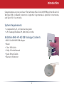
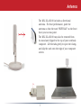
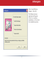
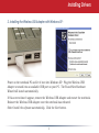
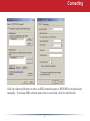
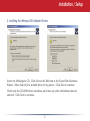
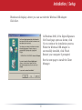
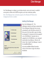
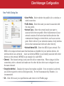
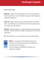
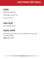
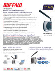
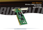
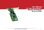
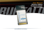
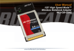
AirStation WLI-U2-AG108HP
User Manual
Wireless 54 Mbps
USB Adapter
High Power Dual A+G Wireless
USB 2.0Interface
Adapter
with Antenna
WLI2-USB-G54
www.buffalotech.com
v. 1.1
Introduction
Congratulations on your purchase! The AirStation WLI-U2-AG108HP High-Power Dual A+G
Wireless USB 2.0 Adapter connects to 2.4ghz 802.11g networks, 2.4ghz 802.11b networks,
and 5ghz 802.11a networks.
System Requirements
• A compatable A, B, or G band access point.
• A PC running Windows XP, 2000, ME, or 98se.
AirStation WHR-HP-AG108 Package Contents
•
•
•
•
•
•
WLI-U2-AG108HP USB Adapter
Stand
5 foot USB Cable
Utility CD with Manual
Quick Setup Guides
Warranty Statement
Antenna
The WLI-U2-AG108 includes a directional
antenna. For best performance, point the
antenna so that the word “BUFFALO” on the front
faces your access point.
The WLI-U2-AG108 may also be removed from
its stand and clipped to the top of your notebook
computer. Lift the tabs gently to open the clamp,
and slip the unit onto the edge of your computer
screen.
Getting Started
1. Installing Drivers:
Insert the AirNavigator CD into the CD-ROM drive of the PC.
If setup.exe does not launch
automatically, click Start
and select Run. Enter
D:\Setup.exe in the Open
field, where D: is the letter
assigned to your CD-ROM.
Click the OK button to
launch the wizard.
AirNavigator
Select Install Wireless
Adapter. Click OK.
The Software License
Agreement will appear.
Click Yes to continue
installation, or No to abort
the installation process.
Installing Drivers
2. Installing the Wireless USB Adapter with Windows XP:
Power on the notebook PC and let it boot into Windows XP. Plug the Wireless USB
Adapter or stand into an available USB port on your PC. The Found New Hardware
Wizard will launch automatically.
If this screen doesn’t appear, remove the Wireless USB Adapter and restart the notebook.
Reinsert the Wireless USB Adapter once the notebook has rebooted.
Select Install the software automatically. Click the Next button.
Installing Drivers
A list of drivers will appear. Choose WLI-U2-AG108HP from the list and click Next .
If Windows warns you that this driver does not pass Windows Logo testing, click Continue
Anyway. When installation is finished, click Finish. Restart your PC if prompted.
Wireless Zero Configuration
3. Using Wireless Zero Configuration:
Normally, Windows XP will scan for available wireless
access points once the Wireless Notebook Adapter
is installed. If Windows detects an access point, a
networking icon appears on the task bar. One or more
wireless networks are available appears as a caption
accompanying the icon.
Notes: If Wireless Zero Configuration is not running,
click Start>Control Panel>Administrative Tools>Services.
Select Automatic in the Startup Type field of the Wireless
Zero Configuration Service to start it.
If you don’t want to use Wireless Zero Config and
would rather use Buffalo’s client utility, or if you have a
Windows 98 or 2000 computer, turn to page 12.
Right click the networking icon in the taskbar and select
View Available Wireless Networks to display a list of
available wireless networks. Select a network and click
Connect.
If the network that you are connecting to is unsecured,
you may need to check the box allowing you to connect
to an unsecured network.
Connecting
Click the Advanced button to enter an SSID network name or WEP/WPA encryption key
manually. To add an SSID network name that is not listed, click the Add button.
Connecting
To enter an encryption key, select the appropriate
wireless network and click the Configure button.
From the pull down menu, select the appropriate type
of Data encryption for the wireless network. Enter
and confirm the Network Key (encryption key). Click
the OK button when finished.
10
Installation with Windows 98/ME/2000
Windows 98/ME/2000
1. Installing the Wireless USB Adapter:
Power on the notebook PC and let it boot into Windows. Plug the Wireless USB Adapter
into an available USB port on your PC. The Found New Hardware Wizard will launch
automatically.
If this screen doesn’t appear, remove the Wireless USB Adapter and restart the notebook.
Reinsert the Wireless USB Adapter once the notebook has rebooted.
Select Install the software automatically. Click the Next button.
11
Installation / Setup
2. Installing the Wireless USB Adapter Drivers:
Insert the AirNavigator CD. Click Next at the Welcome to the Found New Hardware
Wizard. Select Search for a suitable driver for my device. Click Next to continue.
Check only the CD-ROM drives checkbox, and clear any other checkboxes that are
selected. Click Next to continue.
12
Installation / Setup
Windows will display a driver you can use with the Wireless USB Adapter.
Click Next.
In Windows 2000, if the Digital Signature
Not Found page opens as shown, click
Yes to continue the installation process.
When the Wireless USB Adapter is
successfully installed, click Finish.
Restart your computer if prompted.
See the next page to install the Client
Manager.
13
Client Manager
Use Client Manager to configure your wireless network, survey and connect to available
access points, enable and use WEP encryption, and create connection profiles.
Note: Client Manager does not function properly if the Windows XP Wireless Zero
Configuration Service is enabled.
Installing Client Manager
Insert the AirNavigator CD. The
AirNavigator dialog box will open automatically.
If the AirNavigator dialog box does not open
automatically, select Start»Run and enter D:\
Setup.exe in the Open field to open the dialog
box manually. D: represents the letter assigned
to the CD-ROM drive. If another letter is
assigned to the CD-ROM drive, your command
should reflect that difference. Click the OK
button. Select Install Client Manager to launch
the InstallShieldWizard.
Once the InstallShield Wizard launches,
click the Next button to begin the software
installation.
14
Client Manager
Once the Installer Wizard launches, click the Next button to begin the software
installation.
Press I Agree to accept the license agreement and continue the installation process.
15
Client Manager
Press the OK button to finish and close the
installation program.
Press the Exit button to exit the
AirNavigator installation utility.
The Buffalo Client Manager is now installed
and running; right clicking on its icon (the
black notebook icon) will allow you to begin
using it.
16
Client Manager Configuration
Use Client Manager to configure your wireless network. To assist in configuring your
wireless network, Client Manager consists of the Status page, the Survey page, and the
Profiles page. You can access each page by clicking the corresponding button on Client
Manager. In addition to these pages, several dialog boxes are available to meet specialized
configuration needs. You can access the Edit Profile dialog box, New Profile dialog box,
IP Configuration dialog box, or WEP Configuration dialog box using the Client Manager
pages.
Status Page
Click Status to open this page. By
default, this page is displayed when
you start Client Manager. Details of
connection status are displayed.
This page only displays connection
information; no changes to settings are
made here.
This page includes the following
components:
• Adapter Name – Displays the part
number of wireless hardware that is
being used.
17
Client Manager Configuration
• Network Type – Displays what mode the network device is in. Ad-Hoc or
Infrastructure are the available modes.
• Rate – The speed that the two wireless clients are communicating at. If the Client
Manager is not connected to a remote wireless device (access point or another client)
then no rate will be displayed.
• Channel – The channel that the two wireless clients are communicating at. If the
Client Manager is not connected to a remote wireless device (access point of another
client) then no channel will be displayed. The available channels for use are 1-11.
• Security– The type of encryption that the two wireless clients are communicating with.
If the Client Manager is not connected to a remote wireless device (access point of
another client), then ‘No Encryption’ will be displayed.
• IP Address – The IP address of the machine the Client Manager is installed on. If
the Client Manager is not connected to a remote wireless device (access point of
another client) or is not connected to a network with DHCP, then no IP address will be
displayed.
• MAC Address – The MAC address of the wireless client device inside the computer
Client Manager is installed on. If no wireless device is present in the computer, then no
MAC Address will be displayed.
• Signal Strength – Displays the strength of the signal. Signal Strength is based on the
peak signal level the wireless adapter receives from the wireless device to which it is
connected. Next to the signal level is the wireless hardware type that the computer has
available.
18
Client Manager Configuration
Click the Survey tab to open this page. Here, you can survey the area, display available
access points, and connect to available access points.
This page includes the following components:
• Wireless SSID – Displays the SSID associated
with each available access point. The SSID is
the unique network name that functions as an
identifier for your wireless devices. All wireless
devices on a network must use identical SSIDs to
successfully communicate.
• Wireless Mode – Displays the mode/rate set that
the remote wireless device is offering.
• Strength – Displays the relative strength of the
wireless networks.
• Encryption – Displays whether the wireless
network is using any sort of encryption.
Press the Connect button to connect to a listed SSID, or press the Refresh button to
perform another survey and update the survey list.
19
Client Manager Configuration
Once the Connect button is pressed, you will be prompted to enter any encryption related
information.
The Encryption drop down list allows you to
select the type of encryption for the network.
The correct encryption type should already be
selected automatically.
The Encryption Key is where the actual key
required by the wireless network must be
inputted. Please consult your wireless access
point or router’s documentation for proper
input of the encryption keys. Some wireless
networks may allow you to enter multiple keys;
four separate fields are available for this. If your
network only uses one encryption key, then
please use field 1 to enter your key.
The Register Profile option will store this wireless
network in your profiles. This means you will automatically connect to this network
when inside its range. This is recommended if you plan on using this wireless network
more than once.
Press the Connect button once you have completed entering the information.
20
Client Manager Configuration
Profiles Page
Click the Profiles tab to open this page.
Use this page to access your profiles.
Profiles allow you to save the information
associated with a specific wireless
network so you can quickly and easily
connect to that network when you are in
that location. The Profiles page allows you
to add, delete, and edit your profiles, as
well as import and export data.
• Connect – Click the Connect button to
connect to the selected profile and return
to the Status page.
• Edit – Click the Edit button to edit
the selected profile’s settings. The Edit
button also allows you to delete a profile no longer used or required.
• Add – Click the Add button to add a profile manually. You will need important
information such as SSID, encryption settings, and network type.
21
Client Manager Configuration
New Profile Dialog Box
• Select Profile – Select whether the profile is for a wireless or
wired connection.
• Profile Name – Enter the name you want to associate with
the new profile.
• Network Type – Select the network mode you want to
associate with the new profile. Select Infrastructure if your
network consists of both wired and wireless devices that
communicate through a central device, such as an access
point. Select Ad-hoc if your network consists of only wireless
devices that communicate with each other directly.
• Network Name SSID – Enter the SSID of your network. The
SSID is the unique network name that functions an identifier for your wireless devices. All
wireless devices on a network
must use identical SSIDs to successfully associate with other
devices on the network. MYSSID is an example of a valid SSID.
• Channel – The channel setting is only used for Ad-hoc connections. When using an Ad-hoc
connection, select a channel and make sure the other Ad-hoc devices are configured to use
the same channel.
• Encryption Method – Displays the types of encryption available. Once encryption is selected,
you will be required to enter an Encryption Key. For the Transmission Key Number, 1 is
recommended.
• OK – Click OK to save your specifications and return to the Profiles page.
22
Client Manager Configuration
Advanced Profile Options
• Network Tab – Displays the network information tab. A static IP can be specified for
this wireless profile here. It is not recommended to change any of these settings unless
specified by an administrator.
• Browser Tab – Displays settings to change your browser preferences for this wireless
profile. A specific home page can be specified when connected to this wireless profile
as can specific proxy server addresses.
• Printers Tab – Displays the printers tab. A specific default printer can be associated to
this profile. Thus, when connected to this profile, a specific printer will be used as the
default printer.
• OK – Click the OK button to save your specifications and return to the Profiles page.
• AOSS Icon – To automatically add the USB wireless client to your
network, just click this icon and then hold down the AOSS button on
your wireless router for a few seconds.
Check your package for an AOSS Manual, which will give more
information on using AOSS.
23
Wireless Zero Configuration
Wireless Zero Configuration Service (Windows XP)
Windows XP offers the Wireless Zero Configuration Service to support 802.11a, 802.11b
and 802.11g wireless networking. This service automatically polls the area for available
wireless access points. If an available wireless access point is found, Windows attempts
to connect to the access point. If no available wireless access points are found, you must
manually add the access points.
Note: The Wireless Zero Configuration Service and Client Manager do not function properly together. If you want to use Client Manager, disable the Wireless Zero Configuration
Service.
Enabling the Wireless Zero Configuration Service
Select Start»Control Panel»Administrative Tools»Services to open the Services window. Select Automatic in the Startup Type field of Wireless Zero Configuration Service to enable
the Wireless Zero Configuration Service.
Note: Windows XP’s default setting for Wireless Zero Configuration Service is Automatic
(on).
Disabling the Wireless Zero Configuration Service
Select Start»Control Panel»Administrative Tools»Services to open the Services window.
Select Disabled in the Startup Type field of Wireless Zero Configuration Service to disable
the Wireless Zero Configuration Service.
24
Specifications
Wireless LAN Interface
Standards Compliance
IEEE802.11g, IEEE802.11b, IEEE802.11a
Communication Protocol
Direct Sequence Spread Spectrum
(DS-SS), Half Duplex
Frequency Range
2.412-2.472Ghz; 5.18-5.32GHz
Transmission Rate
802.11a: 1, 2, 5.5, 11, 18, 24, 36, 48, 54Mbps
802.11g: 1, 2, 5.5, 11, 18, 24, 36, 48, 54Mbps
Access Mode
Infrastructure mode, Ad-Hoc mode
Security
128/64 Bit WEP, WPA, 802.1x, WPA-PSK, TKIP, AES
Others
Interface
USB 2.0 (Compatible USB 1.1)
Power Consumption
460mA (max)
Environmental Operation
0-55ºC, 20-80% (non-condensing)
25
Troubleshooting / FAQ
Troubleshooting / FAQ
Use this section to locate answers to frequently asked questions.
What should I do if I already have a version of Client Manager on my PC?
Update your Client Manager to the version on the CD. If you do not update your Client
Manager, there could be a loss of functionally, as some versions of Client Manager will
not work properly with the Wireless USB Adapter. Before updating Client Manager, you
must uninstall all previous versions of Client Manager. To update your Client Manager,
load the Air Navigator CD and select Install Client Manager.
Why won't all my network clients work?
Some operating systems support only a limited number of network clients.
Windows 98/Me: These operating systems support only four network clients. If you install more than four network clients, only the first four clients you install will work.
Will Client Manager support all operating systems?
Client Manager and the AirStation Wireless USB Adapter currently support only Windows
98/ME/2000/XP. They do not currently support Windows NT, Mac OS, or Linux.
26
Troubleshooting / FAQ
Why won't Client Manager function properly?
In Windows XP, the Wireless Zero Configuration Service conflicts with Client Manager.
You must disable the Select Wireless Zero Configuration Service before using Client
Manager. Start»Control Panel»Administrative Tools»Services to open the Services window.
Select Disabled in the Startup Type field of Wireless Zero Configuration Service to disable
the Wireless Zero Configuration Service.
I have more than one Air Navigator CD. Do I need more than one CD?
No. You receive the same Air Navagator CD with each Buffalo Technology access point
and wireless adapter. The CDs are identical and you only need one copy.
27
Glossary
10BaseT or 100BaseTx: 802.3 based Ethernet network that uses UTP (Unshielded
twisted pair) cable and a star topology. 10
is 10 Mbps and 100 is 100 Mbps.
Client: A PC or workstation on a network.
802.1x: The standard for wireless LAN
authentication used between an AP and a
client. 802.1x with EAP will initiate key
handling.
DCE (Data Communications Equipment):
Hardware used for communication with a
Data Terminal Equipment (DTE) device.
Cross-Over Wiring: A UTP cable that has
its transmit and receive pair crossed to allow communications between two devices.
Default Gateway: The IP Address of either
the nearest router or server for the LAN.
Ad-Hoc Network: The wireless network
based on a peer-to-peer communications
session. Also referred to as AdHoc.
Default Parameter: Parameter set by the
manufacturer.
Bandwidth: The transmission capacity of
a computer or a communication channel,
stated in Megabits per second (Mbps).
BSS (Basic Service Set): An 802.11 networking framework that includes an Access
Point.
Bus Mastering: A system in which the
specified Input/Output device (e.g. NIC
Card) can perform tasks without the intervention of the CPU.
28
Destination Address: The address portion of a packet that identifies the intended
recipient station.
DHCP (Dynamic Host Configuration
Protocol): Based on BOOTP, it uses a pool
of IP addresses, which it assigns to each
device connected to it, and retrieves the
address when the device becomes dormant
for a period of time.
Glossary
DNS (Domain Name System): System
used to map readable machine names into
IP addresses
Bandwidth: The transmission capacity of
a computer or a communication channel,
stated in Megabits per second (Mbps).
Driver: Software that interfaces a computer with a specific hardware device.
BSS (Basic Service Set): An 802.11 networking framework that includes an Access
Point.
DSSS (Direct Sequence Spread Spectrum): Method of spreading a wireless
signal into wide frequency bandwidth.
Bus Mastering: A system in which the
specified Input/Output device (e.g. NIC
Card) can perform tasks without the intervention of the CPU.
DTE (Data Terminal Equipment): Device
that con10BaseT or 100BaseTx: 802.3
based Ethernet network that uses UTP
(Unshielded twisted pair) cable and a star
topology. 10 is 10 Mbps and 100 is 100
Mbps.
Client: A PC or workstation on a network.
Cross-Over Wiring: A UTP cable that has
its transmit and receive pair crossed to allow communications between two devices.
802.1x: The standard for wireless LAN
authentication used between an AP and a
client. 802.1x with EAP will initiate key
handling.
DCE (Data Communications Equipment):
Hardware used for communication with a
Data Terminal Equipment (DTE) device.
Default Gateway: The IP Address of either
the nearest router or server for the LAN.
Ad-Hoc Network: The wireless network
based on a peer-to-peer communications
session. Also referred to as AdHoc.
Default Parameter: Parameter set by the
manufacturer.
29
Glossary
Destination Address: The address portion of a packet that identifies the intended
recipient station.
Dynamic IP Address: An IP address that
is automatically assigned to a client station
in a TCP/IP network, typically by a DHCP
server.
DHCP (Dynamic Host Configuration
Protocol): Based on BOOTP, it uses a pool
of IP addresses, which it assigns to each
device connected to it, and retrieves the
address when the device becomes dormant
for a period of time.
ESS (Extended Service Set): A set of two
or more BSSs that form a single sub-network. ESS-ID is user identification used in
the ESS LAN configuration.
Ethernet: The most widely used architecture for Local Area Networks (LANs). It is
a shared-media network architecture. The
IEEE 802.3 standard details its functionality.
DNS (Domain Name System): System
used to map readable machine names into
IP addresses
Driver: Software that interfaces a computer with a specific hardware device.
Ethernet cable: A wire similar to telephone cable that carries signals between
Ethernet devices.
DSSS (Direct Sequence Spread Spectrum): Method of spreading a wireless
signal into wide frequency bandwidth.
File and Print Sharing: A Microsoft application that allows computers on a network
to share files and printers.
DTE (Data Terminal Equipment): Device
that controls data flowing to and from a
computer.
30
Glossary
Firmware: Programming inserted into
programmable read-only memory, thus
becoming a permanent part of a computing
device.
IP (Internet Protocol) Address: A unique
32-binary-digit number that identifies each
sender or receiver of information sent in
packets.
Frame: A fixed block of data, transmitted as a single entity. Also referred to as
packet.
Infrastructure: A wireless network or
other small network in which the wireless
network devices are made a part of the
network through the Access Point.
Full-Duplex: To transmit on the same
channel in both directions simultaneously.
ISP (Internet Service Provider): A company that provides access to the Internet
and other related services.
Gbps (Giga Bits per second): One billion
bits per second.
IV (Initialization Vector): The header
section of a message packet.
Half-duplex: To transmit on the same
channel in both directions, one direction at
a time.
LAN (Local Area Network): A group of
computers and peripheral devices connected to share resources.
Hub: A device which allows connection
of computers and other devices to form a
LAN.
LED (Light Emitting Diode): The lights
on a hardware device representing the activity through the ports.
IEEE (Institute of Electrical and Electronics Engineers): The professional
organization which promotes development
of electronics technology.
31
Glossary
MAC (Medium Access Control) Address:
A unique number that distinguishes network cards.
NIC (Network Interface Card): An expansion card connected to a computer so the
computer can be connected to a network.
Mbps (Mega Bits Per Second): A measurement of millions of bits per second.
Packet: A block of data that is transferred
as a single unit, also called a frame or a
block.
MDI/X (Media Dependent Interface/
Cross-over): Port on a network hub or
switch that crosses the incoming transmit
lines with the outgoing receive lines.
Packet Filtering: Discarding unwanted
network traffic based on its originating address or its type.
MHz (MegaHertz): One million cycles per
second.
PCI (Peripheral Component Interconnect): A bus that is connected directly to
the CPU.
MIB II: A database containing performance information and statistics on each
device in a network.
PCMCIA (Personal Computer Memory
Card International Association) Card:
Removable module that adds features to a
portable computer.
MIPS (Million Instructions Per Second):
A measurement of processing speed.
Ping (Packet Internet Groper): An Internet utility used to determine whether a
particular IP address is online.
NAT (Network Address Translation): An
internet standard that enables a LAN to
use one set of IP addresses for internal
traffic and a second set for external traffic.
32
Glossary
Plug and Play: Hardware that, once installed (“plugged in”), can immediately be
used (“played”), as opposed to hardware
that requires manual configuration.
to be extended to accommodate additional
workstations.
PoE (Power over Ethernet): A mechanism
to send DC power to a device using a CAT5
Ethernet cable.
RJ-45 connector: An 8-pin connector
used between a twisted pair cable and a
data transmission device.
PPPoE (Point-to-Point Protocol over
Ethernet): A specification for connecting
users on an Ethernet line to the Internet
through a common broadband medium.
RC4: The encryption algorithm that is
used in WEP.
ROM (Read Only Memory): Permanent
memory.
Router: Device that can connect individual LANs and remote sites to a server.
Protocol: A standard way of exchanging
information between computers.
Roaming: The ability to use a wireless
device while moving from one access point
to another without losing the connection.
RADIUS (Remote Authentication Dial
In User Service): A server that issues
authentication key to clients.
Script: A macro or batch file containing
instructions and used by a computer to
perform a task.
RAM (Random Access Memory): Nonpermanent memory.
Server: Any computer that makes files or
peripheral devices available to users of the
network and has a resident Network OS.
Repeater Hub: A device that collects,
strengthens and transmits information to
all connected devices, allowing the network
33
Glossary
SMTP (Simple Mail Transfer Protocol):
The protocol used to define and deliver
electronic mail (E-mail) from one location
to another.
SNMP (Simple Network Management Protocol: An application layer protocol that
outlines the formal structure for communication among network devices.
Static IP Address: A permanent IP address is assigned to a node in a TCP/IP
network. Also known as global IP.
TFTP (Trivial File Transfer Protocol):
Simple form of FTP (File Transfer Protocol),
which Uses UDP (User Datagram Protocol),
rather than TCP/IP for data transport and
provides no security features.
TKIP (Temporal Key Integrity Protocol):
An encryption method replacing WEP.
TKIP uses random IV and frequent key
exchanges.
Topology: The shape of a LAN (Local Area
Network) or other communications system.
STP (Shielded Twisted Pair): Twisted Pair
cable wrapped in a metal sheath to provide
extra protection from external interfering
signals.
Twisted Pair: Cable that comprises 2
or more pair of insulated wires twisted
together.
UDP (User Datagram Protocol): A communication method (protocol) that offers a
limited amount of service when messages
are exchanged between computers in a
network. UDP is used as an alternative to
TCP/IP.
Subnet Mask: An eight-byte address divided into 4 parts separated by periods.
TCP/IP (Transmission Control Protocol/Internet Protocol: Protocol used by
computers when communicating across
the Internet or Intranet.
34
Uplink: Link to the next level up in a communication hierarchy.
WLAN (Wireless LAN): A LAN topology using wireless devices.
UTP (Unshielded Twisted Pair) cable:
Two or more unshielded wires twisted together to form a cable.
VPN (Virtual Private Network): A security
method to connect remote LAN users to a
corporate LAN system.
WAN (Wide Area Network): A networking
system covering a wide geographical area.
WEP (Wired Equivalent Privacy): An
encryption method based on 64 or 128-bit
algorithm.
Web Browser: A software program that allows viewing of web pages.
Wi-Fi (Wireless Fidelity): An organization that tests and assures interoperability
among WLAN devices.
Wire Speed: The maximum speed at
which a given packet can be transferred
using Ethernet and Fast Ethernet standard
specifications.
35
54/108* Disclaimer
* 54 Mbps is the maximum wireless signal rate derived from IEEE Standard
802.11a and 802.11g specifications. 108 Mbps is the maximum wireless
signal rate derived from using channel bonding technology when used
with supported devices. Actual data throughput will vary depending upon
network conditions and environmental factors, including volume of network
traffic, building materials and construction, and network overhead.
36
FCC / CE Information
Federal Communication Commission Interference Statement
This equipment has been tested and found to comply with the limits for a Class B digital
device, pursuant to Part 15 of the FCC Rules. These limits are designed to provide reasonable
protection against harmful interference in a residential installation. This equipment
generates, uses and can radiate radio frequency energy and, if not installed and used in
accordance with the instructions, may cause harmful interference to radio communications.
However, there is no guarantee that interference will not occur in a particular installation.
If this equipment does cause harmful interference to radio or television reception, which
can be determined by turning the equipment off and on, the user is encouraged to try to
correct the interference by one of the following measures:
• Reorient or relocate the receiving antenna.
• Increase the separation between the equipment and receiver.
• Connect the equipment into an outlet on a circuit different from that to which the
receiver is connected.
• Consult the dealer or an experienced radio/TV technician for help.
FCC Caution: To assure continued compliance, (example - use only shielded interface cables
when connecting to computer or peripheral devices). Any changes or modifications not
expressly approved by the party responsible for compliance could void the user’s authority
to operate this equipment.
This device complies with Part 15 of the FCC Rules. Operation is subject to the following two
conditions: (1) This device may not cause harmful interference, and (2) this device must accept
any interference received, including interference that may cause undesired operation.
37
FCC / CE Information
IMPORTANT NOTE:
FCC RF Radiation Exposure Statement:
This equipment complies with FCC RF radiation exposure limits set forth for an uncontrolled
environment. This equipment should be installed and operated with a minimum distance
of 20 centimeters between the radiator and your body.
This transmitter must not be co-located or operating in conjunction with any other antenna
or transmitter.
R&TTE Compliance Statement
This equipment complies with all the requirements of the DIRECTIVE 1999/5/EC OF THE
EUROPEAN PARLIAMENT AND THE COUNCIL of 9 March 1999 on radio equipment and
telecommunication terminal Equipment and the mutual recognition of their conformity
(R&TTE). The R&TTE Directive repeals and replaces in the directive 98/13/EEC
(Telecommunications Terminal Equipment and Satellite Earth Station Equipment) As of
April 8, 2000.
Safety
This equipment is designed with the utmost care for the safety of those who install and
use it. However, special attention must be paid to the dangers of electric shock and static
electricity when working with electrical equipment. All guidelines of this manual and of
38
FCC / CE Information
the computer manufacturer must therefore be allowed at all times to ensure the safe use
of the equipment.
EU Countries intended for use
The ETSI version of this device is intended for home and office use in Austria, Belgium,
Denmark, Finland, France (with Frequency channel restrictions), Germany, Greece,
Iceland, Ireland, Italy, Luxembourg, Norway, The Netherlands, Portugal, Spain, Sweden,
Switzerland and United Kingdom.
The ETSI version of this device is also authorized for use in EFTA member states Iceland,
Liechtenstein, Norway and Switzerland.
EU Countries Not intended for use
None.
Potential restrictive use
France: Only channels 10,11,12, and 13.
39
Federal Communication Commission Declaration of Conformity ( DoC ) Statement
Model No: WHR-HP-AG108
AirStation High Power Dual A+G SmartRouter
Buffalo Inc.
15, Shibata Hondori 4-chrome
Minami-ku, Nagoya 457-8520
Japan
01181-52-241-7980
This equipment has been tested and found to comply with the limits for a Class B digital
device, pursuant to Part 15 of the FCC rules. These limits are designed to provide reasonable
protection against harmful interference in a residential installation. This equipment generates,
uses, and can radiate radio frequency energy and, if not installed and used in accordance with
the instructions, may cause harmful interference to radio communications. However, there is
no guarantee that interference will not occur in a particular installation. If this equipment
does cause harmful interference to radio or television reception, which can be determined by
turning the equipment off and on, the user is encouraged to try to correct the interference by
40
one or more of the following measures:
• Reorient or relocate the receiving antenna.
• Increase the separation between the equipment and receiver.
• Connect the equipment into an outlet on a circuit different from that to which the receiver
is connected. • Consult the dealer or an experienced radio/TV technician for help.
This device complies with Part 15 of the FCC Rules. Operation is subject to the following
two conditions: (1) This device may not cause harmful interference, and (2) This device
must accept any interference received, including interference that may cause undesired
operation.
Caution:
Any changes or modifications not expressly approved by the party responsible for product
compliance could void the user’s authority to operate the equipment.
Within the 5.15-to-5.25-GHz band, UNII devices are restricted to indoor operations to reduce
any potential for harmful interference to co-channel Mobile Satellite Systems (MSS) operations
Caution:
Exposure to radio frequency radiation ( below is for mobile device )
To comply with FCC RF exposure compliance requirements, a separation distance of at least
20 cm must be maintained between the antenna of this device and all persons. This device
must not be co-located or operating in conjunction with any other antenna or transmitter.
41
Caution Exposure to radio frequency radiation (below is for portable device)
To comply with FCC RF exposure compliance requirements, this device must not be colocated
or operating in conjunction with any other antenna or transmitter.
b. Industry Canada Portion
Canada Regulatory Compliance Statement
This Class B digital apparatus complies with Canadian ICES-003.
Cet appareil numériqué de la classe B est conformé à la norme NMB-003 du
Canada.
For Customers in Canada
This device complies with RSS 210 of Industry Canada (IC).
Operation is subject to the following two conditions:
(1) this device may not cause interference, and
(2) this device must accept any interference, including interference that may cause undesired
operation of this device.
L’ utilisation de ce dispositif est autorisée seulement aux conditions suivantes :
(1) il ne doit pas produire de brouillage et
(2) l’ utilisateur du dispositif doit étre prêt à accepter tout brouillage radioélectrique reçu,
même si ce brouillage est susceptible de compromettre le fonctionnement du dispositif.
42
Caution: Within the 5.15-to-5.25-GHz band, UNII devices are restricted to indoor operations to reduce
any potential for harmful interference to co-channel Mobile Satellite Systems (MSS) operations
Exposure to radio frequency radiation (below statement applied to mobile or portable device)
The installer of this radio equipment must ensure that the antenna is located or pointed such
that it does not emit RF field in excess of Health Canada limits for the general population;
consult Safety Code 6, obtainable from Health Canada’s website at www.hc-sc.gc.ca/rpb.
c. EU Portion
European Community Declaration of Conformity with Regard to the R&TTE Directive
1999/5/EC
The following standards were applied: (Omni)
• Radio: EN 300-328 v1.6.1 (2.4-GHz operation)
• EN 301-893 v1.2.3 (5-GHz operation)
• EMC: EN 301.489-1 v1.4.1, EN 301.489-17 v1.2.1
• Safety: IEC 60950 ( 1999 3rd Edition with Amend. 1,2,3,4 ) & EN 60950 ( 2000 )
The following CE mark is affixed to the device:
43
Note: This equipment is intended to be used in all EU and EFTA countries. Outdoor use may
be restricted to certain frequencies and/or may require a license for operation. For more
details, contact your customer service representative.
To comply with RF exposure compliance requirements, a separation distance of at least 20
cm must be maintained between the antenna of this device and all persons. This device must
not be co-located or operating in conjunction with any other antenna or transmitter.
Member States shall ensure that the manufacturer or the person responsible for placing the
apparatus on the market provides information for the user on the intended use of the
apparatus, together with the declaration of conformity to the essential requirements. Where it
concerns radio equipment, such information shall be sufficient to identify on the packaging
and the instructions for use of the apparatus the Member States or the geographical area
within a Member State where the equipment is intended to be used and shall alert the user by
the marking on the apparatus referred to in Annex VII, paragraph 5, to potential restrictions
or requirements for authorization of use of the radio equipment in certain Member States.
44
Declaration of Conformity with Regard to the R&TTE Directive 1999/5/EC
Česky
[Czech]
Buffalo Technology Inc. tímto prohlašuje, že tento AirStation WHR-HP-AG108 je ve shodě se základními
požadavky a dalšími příslušnými ustanoveními směrnice 1999/5/ES.
Dansk
[Danish]
Undertegnede Buffalo Technology Inc. erklærer herved, at følgende udstyr AirStation WHR-HP-AG108
overholder de væsentlige krav og øvrige relevante krav i direktiv 1999/5/EF.
Deutsch
[German]
Hiermit erklärt Buffalo Technology Inc. dass sich das Gerät AirStation WHR-HP-AG108 in Übereinstimmung
mit den grundlegenden Anforderungen und den übrigen einschlägigen Bestimmungen der Richtlinie
1999/5/EG befindet.
Eesti
[Estonian]
Käesolevaga kinnitab Buffalo Technology Inc. seadme AirStation WHR-HP-AG108 vastavust direktiivi 1999/5/
EÜ põhinõuetele ja nimetatud direktiivist tulenevatele teistele asjakohastele sätetele.
English Hereby, Buffalo Technology Inc. declares that this AirStation WHR-HP-AG108 is in compliance
45
with the essential requirements and other relevant provisions of Directive 1999/5/EC.
Español
[Spanish]
Por medio de la presente Buffalo Technology Inc. declara que el AirStation WHR-HP-AG108 cumple con
los requisitos esenciales y cualesquiera otras disposiciones aplicables o exigibles de la Directiva
1999/5/CE.
Ελληνική
[Greek]
ΜΕ ΤΗΝ ΠΑΡΟΥΣΑ Buffalo Technology Inc. ΔΗΛΩΝΕΙ ΟΤΙ AirStation WHR-HP-AG108
ΣΥΜΜΟΡΦΩΝΕΤΑΙ ΠΡΟΣ ΤΙΣ ΟΥΣΙΩΔΕΙΣ ΑΠΑΙΤΗΣΕΙΣ ΚΑΙ ΤΙΣ ΛΟΙΠΕΣ ΣΧΕΤΙΚΕΣ ΔΙΑΤΑΞΕΙΣ
ΤΗΣ ΟΔΗΓΙΑΣ 1999/5/ΕΚ.
Français
[French]
Par la présente Buffalo Technology Inc. déclare que l’appareil AirStation WHR-HP-AG108 est conforme
aux exigences essentielles et aux autres dispositions pertinentes de la directive 1999/5/CE.
Italiano
[Italian]
Con la presente Buffalo Technology Inc. dichiara che questo AirStation WHR-HP-AG108 è conforme
ai requisiti essenziali ed alle altre disposizioni pertinenti stabilite dalla direttiva 1999/5/CE.
46
with the essential requirements and other relevant provisions of Directive 1999/5/EC.
Español
[Spanish]
Por medio de la presente Buffalo Technology Inc. declara que el AirStation WHR-HP-AG108 cumple con
los requisitos esenciales y cualesquiera otras disposiciones aplicables o exigibles de la Directiva
1999/5/CE.
Ελληνική
[Greek]
ΜΕ ΤΗΝ ΠΑΡΟΥΣΑ Buffalo Technology Inc. ΔΗΛΩΝΕΙ ΟΤΙ AirStation WHR-HP-AG108
ΣΥΜΜΟΡΦΩΝΕΤΑΙ ΠΡΟΣ ΤΙΣ ΟΥΣΙΩΔΕΙΣ ΑΠΑΙΤΗΣΕΙΣ ΚΑΙ ΤΙΣ ΛΟΙΠΕΣ ΣΧΕΤΙΚΕΣ ΔΙΑΤΑΞΕΙΣ
ΤΗΣ ΟΔΗΓΙΑΣ 1999/5/ΕΚ.
Français
[French]
Par la présente Buffalo Technology Inc. déclare que l’appareil AirStation WHR-HP-AG108 est conforme
aux exigences essentielles et aux autres dispositions pertinentes de la directive 1999/5/CE.
Italiano
[Italian]
Con la presente Buffalo Technology Inc. dichiara che questo AirStation WHR-HP-AG108 è conforme
ai requisiti essenziali ed alle altre disposizioni pertinenti stabilite dalla direttiva 1999/5/CE.
47
Latviski
[Latvian]
Ar šo Buffalo Technology Inc. deklarē, ka AirStation WHR-HP-AG108 atbilst Direktīvas 1999/5/EK būtiskajām
prasībām un citiem ar to saistītajiem noteikumiem.
Lietuvių
[Lithuanian]
Šiuo Buffalo Technology Inc. deklaruoja, kad šis AirStation WHR-HP-AG108 atitinka esminius reikalavimus
ir kitas
1999/5/EB Direktyvos nuostatas.
Nederlands
[Dutch]
Hierbij verklaart Buffalo Technology Inc. dat het toestel AirStation WHR-HP-AG108 in overeenstemming is
met de essentiële eisen en de andere relevante bepalingen van richtlijn 1999/5/EG.
Malti
[Maltese]
Hawnhekk, Buffalo Technology Inc. , jiddikjara li dan AirStation WHR-HP-AG108 jikkonforma mal-ħtiġijiet
essenzjali u ma provvedimenti oħrajn relevanti li hemm fid-Dirrettiva 1999/5/EC.
Magyar
[Hungarian]
Alulírott, Buffalo Technology Inc. nyilatkozom, hogy a AirStation WHR-HP-AG108 megfelel a vonatkozó
48
alapvetõ követelményeknek és az 1999/5/EC irányelv egyéb elõírásainak.
Polski
[Polish]
Niniejszym, Buffalo Technology Inc. , deklaruję, że AirStation WHR-HP-AG108 spełnia wymagania zasadnicze
oraz stosowne postanowienia zawarte Dyrektywie 1999/5/EC.
Português
[Portuguese]
Buffalo Technology Inc. declara que este AirStation WHR-HP-AG108 está conforme com os requisitos
essenciais e outras disposições da Directiva 1999/5/CE.
Slovensko
[Slovenian]
Buffalo Technology Inc. izjavlja, da je ta AirStation WHR-HP-AG108 v skladu z bistvenimi zahtevami in
ostalimi relevantnimi določili direktive 1999/5/ES.
Slovensky
[Slovak]
Buffalo Technology Inc. týmto vyhlasuje, že AirStation WHR-HP-AG108 spĺňa základné požiadavky a všetky
príslušné ustanovenia Smernice 1999/5/ES.
Suomi
[Finnish]
Buffalo Technology Inc. vakuuttaa täten että AirStation WHR-HP-AG108 tyyppinen laite on direktiivin
49
1999/5/EY oleellisten vaatimusten ja sitä koskevien direktiivin muiden ehtojen mukainen.
Svenska
[Swedish]
Härmed intygar Buffalo Technology Inc. att denna AirStation WHR-HP-AG108 står I överensstämmelse
med de väsentliga egenskapskrav och övriga relevanta bestämmelser som framgår av direktiv
1999/5/EG.
50
51
Contact Information (North America)
ADDRESS Buffalo Technology (USA), Inc.
4030 West Braker Lane, Suite 120
Austin, TX 78759-5319
GENERAL INQUIRIES Email: [email protected]
TECHNICAL SUPPORT North American Technical Support by phone is available 24 hours a day, 7 days a
week. (USA and Canada).
Toll-free: (866) 752-6210
52
Contact Information (Europe)
ADDRESS Buffalo Technology (Europe), Inc.
176 Buckingham Avenue,
Slough, Berkshire, SL1 4RD
United Kingdom
GENERAL INQUIRIES Email: [email protected]
TECHNICAL SUPPORT Technical Support in Europe is available between the hours of 9am-6pm (GMT) Monday to Thursday and 9am-4:30pm (GMT) Friday for this product. Customers in Europe
can obtain Technical Support using the following information:
E-mail: [email protected] | Web: www.buffalo-technology.com
53