1
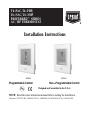
T6−PAC, T6−PHP,
T6−NAC, T6−NHP
PREFERREDt SERIES
AC / HP THERMOSTAT
Installation Instructions
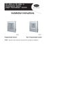
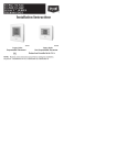
A07045
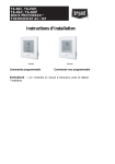
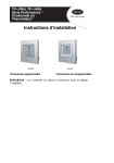
Programmable Control
A07044
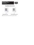
Non-Programmable Control
Designed and Assembled in the U.S.A.
NOTE: Read the entire instruction manual before starting the installation.
US patents: US7287709 B2, US20080147242 A1, USD582800 SI, US20060165149 A1, US6956463 B2.
TABLE OF CONTENTS
PAGE
SAFETY CONSIDERATIONS . . . . . . . . . . . . . . . . . . . . . . . . . . . . . . . . . . . . 1
INTRODUCTION . . . . . . . . . . . . . . . . . . . . . . . . . . . . . . . . . . . . . . . . . . . . . . 2
INSTALLATION CONSIDERATIONS . . . . . . . . . . . . . . . . . . . . . . . . . . . . . . 3
INSTALLATION . . . . . . . . . . . . . . . . . . . . . . . . . . . . . . . . . . . . . . . . . . . . . . . 6
SYSTEM START−UP AND CHECKOUT . . . . . . . . . . . . . . . . . . . . . . . . . . 38
OPERATIONAL INFORMATION . . . . . . . . . . . . . . . . . . . . . . . . . . . . . . . . 41
TROUBLESHOOTING . . . . . . . . . . . . . . . . . . . . . . . . . . . . . . . . . . . . . . . . . 45
WIRING DIAGRAMS . . . . . . . . . . . . . . . . . . . . . . . . . . . . . . . . . . . . . . . . . . 49
THERMOSTAT CONFIGURATION RECORD . . . . . . . . . . . . . . . . . . . . . . 58
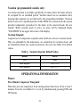
SAFETY CONSIDERATIONS
Read and follow manufacturer instructions carefully. Follow all local electrical
codes during installation. All wiring must conform to local and national electrical
codes. Improper wiring or installation may damage AC/HP Control.
Recognize safety information. This is the safety−alert symbol
. When you see
this symbol on the equipment and in the instruction manual, be alert to the
potential for personal injury.
Understand the signal words DANGER, WARNING, and CAUTION. These
words are used with the safety−alert symbol. DANGER identifies the most
serious hazards which will result in severe personal injury or death. WARNING
signifies a hazard which could result in personal injury or death. CAUTION is
used to identify unsafe practices which may result in minor personal injury or
product and property damage. NOTE is used to highlight suggestions which will
result in enhanced installation, reliability, or operation.
1
INTRODUCTION
Bryant’s 7−day, 5/2−day, 1−day programmable and non−programmable
Preferred Series Thermostat Control is a wall−mounted, low−voltage
temperature control in either a single unit or a two−piece unit. In two−piece
configuration, the relays are located near the equipment and a two−wire
connection is used between the Display Module and the Equipment Control
Module. Single−piece installation requires more wiring and results in a higher
profile. The Preferred Series Thermostat has no need for batteries to store
user−configured settings in memory. During power loss its internal memory
saves settings for unlimited time, and the clock continues to run for at least 24
hours. An extension of Bryant’s proven line of thermostats; it provides separate
setpoints for heating and cooling.
In the control’s programmable configuration, different heating and cooling
setpoints and times are programmable for 4 periods per day or 2 periods per day.
Programming can be done for 7 days per week, 5/2 days per week, or 1 day. The
programmable Thermostat Control can also be user configured as a
non−programmable Thermostat Control.
The non−programmable Thermostat Control features Touch ’N’ Go settings
for quick and easy temperature change without complicated programming
schedules. And, its Touch ’N’ Go technology enables the user to switch between
three different user−configurable settings through intuitive buttons located just
below the display.
2
INSTALLATION CONSIDERATIONS
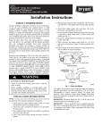
Power
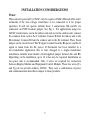
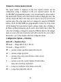
This control is powered by 24VAC only. It requires 24VAC (Rh and/or Rc and C
terminals) of the low−voltage transformer to be connected to it for proper
operation. It will not operate without these 2 connections. Rh and Rc are
connected via PCB breakout jumper. See Fig. 1. For applications using two
24VAC transformers, one in the indoor unit and one in the outdoor unit, connect
the common from each to the C terminal. Connect R from the indoor unit to the
Rh terminal. Connect R from the outdoor unit to the Rc terminal. Then, break
jumper on the circuit board. The W signal is taken from the Rh power and the G
signal is taken from the Rc power. If thermostat has been installed in a
two−transformer application that is later changed to a single−transformer
installation, installer must install a field supplied jumper between Rc and Rh.
Depending on the installation, up to 14 wires may be required. Installation as
two−piece unit is recommended. Only 2 wires are required for connection
between Display Module and Equipment Control Module. These two wires (V+
and Vg) do not provide ordinary 24VAC. They carry a combination of power
and communications data that is unique to these products.
3
A07052
Fig. 1 − PCB Breakout Jumper
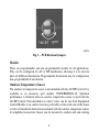
Models
There are programmable and non−programmable models for all applications.
They can be configured for AC or HP installations, allowing it to be used in
place of all Bryant thermostats. Programmable thermostats may be configured as
non−programmable if user desires.
Outdoor Temperature Sensor
The outdoor air temperature sensor is not included with the AC/HP Control. It is
available as an accessory, part number TSTATBBSEN01−B. Optimum
performance is obtained when an outdoor temperature sensor is used with the
AC/HP Control. Plan installation so that 2 wires can be run from Equipment
Control Module to an outdoor location, preferably on the north side of the house
or refer to Installation Instructions included with the outdoor temperature sensor
for simplified connection. Sensor can be mounted to outdoor unit and existing
4
dedicated sensor wires may be used for its connection. Details are provided in
sensor instructions.
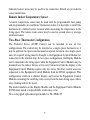
Remote Indoor Temperature Sensor
A remote temperature sensor may be used with the programmable heat pump
and programmable air conditioner thermostats where it is desirable to install the
thermostat in a limited access location while measuring the temperature in the
living space. The remote room sensor may be used as a stand alone or average
with local sensor.
Two−Piece Thermostat Configuration
The Preferred Series AC/HP Control can be installed in one of two
configurations. The control may be installed as a single−piece thermostat or it
may be split into two pieces and mounted in separate locations. As a single−piece
unit, all required wiring must be brought to the Equipment Control Module for
connection to the terminal strip. In two−piece configuration, the Display Module
can be mounted in the living space while the Equipment Control Module may be
mounted near the indoor furnace or fan coil. Connection from the display to the
Equipment Control Module requires only two wires. All other control wires are
connected to the Equipment Control Module from the HVAC equipment. This
configuration results in a slimmer display and locates the Equipment Control
Module containing the switching relays away from the main living space where
relay clicking will not be heard.
The model numbers on the Display Module and the Equipment Control Module
(ECM) must match or unpredictable results may occur.
Two−wire pigtail replacement part number is TX−2WR−05.
5
Wiring
Wire length should be no more than 250 ft (76m). Use 22 AWG for normal
wiring applications. Continuous wire lengths over 100 ft (30.5m) should use 20
AWG or larger.
INSTALLATION
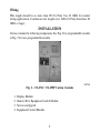
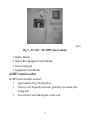
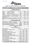
Carton contains the following components. See Fig. 2 for programmable models
or Fig. 3 for non−programmable models.
A07756
Fig. 2 − T6−PAC / T6−PHP Carton Contents
1.
2.
3.
4.
Display Module
Stand−off for Equipment Control Module
Screws and pig tail
Equipment Control Module
6
A07757
Fig. 3 − T6−NAC / T6−NHP Carton Contents
1.
2.
3.
4.
Display Module
Stand−off for Equipment Control Module
Screws and pig tail
Equipment Control Module
AC/HP Control Location
AC/HP Control should be mounted:
Approximately 5 ft (1.5m) from floor.
Close to or in a frequently used room, preferably on an inside partitioning wall.
On a section of wall without pipes or duct work.
7
AC/HP Control should NOT be mounted:
Close to a window, on an outside wall, or next to a door leading to the
outside.
Exposed to direct light or heat from a lamp, sun, fireplace, or other
temperature−radiating objects which could cause a false reading.
Close to or in direct airflow from supply registers and return−air registers.
In areas with poor air circulation, such as behind a door or in an alcove.
Installer should determine whether control will be installed as single−piece or
two−piece. In single−piece configuration, as many as 14 wires may need to run
to wall mounting location for connection to the control. In two−piece
configuration, the Display Module and Equipment Control Module are
connected by two wires.
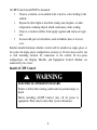
Install AC/HP Control
!
WARNING
ELECTRICAL OPERATION HAZARD
Failure to follow this warning could result in personal injury or
death.
Before installing AC/HP Control, turn off all power to
equipment. There may be more than 1 power disconnect.
8
!
CAUTION
UNIT DAMAGE HAZARD
Failure to follow this caution may result in equipment damage
or improper operation.
Improper wiring or installation may damage AC/HP Control.
Check to make sure wiring is correct before proceeding with
installation or turning on power.
1. Turn off all power to equipment.
2. If an existing thermostat is being replaced
a. Remove existing thermostat from wall.
b. Disconnect wires from existing thermostat, 1 at a time.
c. As each wire is disconnected, record wire color and terminal marking.
d. Discard or recycle old thermostat.
!
CAUTION
ENVIRONMENTAL HAZARD
Failure to follow this caution may result in environmental
damage.
Mercury is a hazardous waste. Federal regulations require that
Mercury be disposed of properly.
9
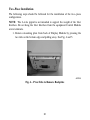
Two−Piece Installation
The following steps should be followed for the installation of the two−piece
configuration.
NOTE: The 2−wire pigtail is not intended to support the weight of the User
Interface. Do not hang the User Interface from the equipment Control Module
screw terminals.
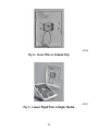
1. Remove mounting plate from back of Display Module by pressing the
two tabs on the bottom edge and pulling away. See Fig. 4 and 5.
A07225
Fig. 4 − Press Tabs to Remove Backplate
10
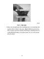
A07226
Fig. 5 − Take Apart
2. Route wires through large hole in mounting base. Level mounting base
against wall (for aesthetic value only—Display Module need not be leveled for proper operation) and mark wall through 4 mounting holes. To
avoid unintended bending of wall plate plastic, use all 4 screws and anchors. See Fig. 6.
11
A07165
3.
4.
5.
6.
Fig. 6 − Backplate Mounting
Drill two 3/16−in. mounting holes in wall where marked. Thermostat may
be mounted to a standard junction box, if desired. Hole pattern on thermostat mounting base matches junction box mounting holes.
Secure rear plastic mounting base to wall with 4 screws and anchors provided. To avoid unintended bending of wall plate plastic, use all 4 screws
and anchors Make sure all wires extend through hole in mounting base.
Adjust length and routing of each wire to reach proper connector block
and terminal on mounting base with 1/4−in. (6mm) extra wire.
Match and connect equipment wires to proper terminals of each connector
block being careful not to over tighten the screws. Correct polarity must
be observed when connecting the two wires from the Equipment Control
Module to the thermostat mounting base. If wires are connected incorrectly, the Display Module will not operate. See Fig. 7, 8 and 9.
12
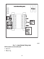
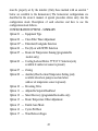
Control Module Wiring Guide
Relays
OAT
RRS
{SRTN
HUM
D1
dry
contact D2
connect V+
to user
interface Vg
Rc
Rh
W / W1
G
Y/Y2
C
O/W2/B
Y1
OAT /
RRS
return
Y used for
single stage
cooling
Y1 used for
multi-speed
cooling
Y1 = stage 1
Y2 = stage 2
A07687
Fig. 7 − Control Module Wiring Guide
HUM terminal is not used on this model.
Red is V+
Black is Vg
13
A07166
Fig. 8 − Secure Wires to Terminal Strip
A07167
Fig. 9 − Connect Pigtail Wires to Display Module
14
NOTE: The 2−wire pigtail is not intended to support the weight of the User
Interface. Do not hang the User Interface from the equipment Control Module
screw terminals.
Red is V+
Black is Vg
7. Push any excess wire into wall and against mounting base. Seal hole in
wall to prevent air leaks. Leaks can affect operation and cause incorrect
temperature and/or humidity measurement.
8. Make sure to attach 2−wire pigtail to Display Module mounting base. It is
packed loose in the box from the factory. Then attach 2−wire pigtail to the
back of the Display Module via 2 pin, keyed connector.
9. Reattach Display Module body to mounting base by first setting on at top
of mounting base and then push bottom corners of Display Module to
snap into place. See Fig. 10.
A07169
Fig. 10 − Attach Display to Backplate
15
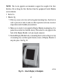
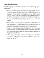
10. Find suitable indoor mounting location for Equipment Control Module,
either near or on equipment. See Fig. 11.
IMPORTANT NOTE: Equipment Control Module should not be mounted
to duct work or below any other controls or equipment (i.e. humidistat,
humidifier, etc.).
A07217
Fig. 11 − Equipment Control Module on Equipment
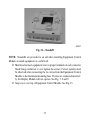
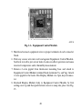
11. Route wires through rear of Equipment Control Module using either a
clearance hole or supplied standoff. See Fig. 12.
16
A07227
Fig. 12 − Standoff
NOTE: Standoffs are provided as an aid when installing Equipment Control
Module on inside equipment or a solid wall.
12. Match and connect equipment wires to proper terminals of each connector
block being careful not to over tighten the screws. Correct polarity must
be observed when connecting the two wires from the Equipment Control
Module to the thermostat mounting base. If wires are connected incorrectly, the Display Module will not operate. See Fig. 7, 8 and 9.
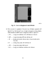
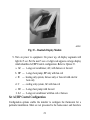
13. Snap cover over top of Equipment Control Module. See Fig. 13.
17
A07218
Fig. 13 − Cover on Equipment Control Module
14. Turn on power to equipment. On power up, all display segments will
light for 5 sec. For the next 5 sec a 2−digit code appears on large display
which identifies AC/HP Control configuration. Refer to Option 33.
a. AC — 1−stage air conditioner, AC, with furnace or fan coil
b. HP — 1−stage heat pump, HP only with fan coil
c. H — heating only system, furnace only or fan coil with electric
heat only
d. C — cooling only system, AC with fan coil
e. H2 — 2−stage heat pump with fan coil
f. A2 — 2−stage air conditioner with fan coil or furnace
18
Single−Piece Installation
The following steps should be followed for the installation of the single−piece
configuration.
1. Remove cover from Equipment Control Module by pressing the two tabs
on the bottom edge and pulling away. Route wires through large hole in
Equipment Control Module. Level Equipment Control Module against
wall (for aesthetic value only − Equipment Control Module need not be
leveled for proper operation) and mark wall through 4 mounting holes.
To avoid unintended bending of wall plate plastic, use all 4 screws and
anchors.
2. Drill four 3/16−in. mounting holes in wall where marked. Thermostat
may be mounted to a standard junction box if desired. Hole pattern on
Equipment Control Module matches junction box mounting holes.
3. Secure rear plastic Equipment Control Module to wall with 4 screws and
anchors provided. To avoid unintended bending of wall plate plastic, use
all 4 screws and anchors. Make sure all wires extend through hole in
Equipment Control Module.
4. Adjust length and routing of each wire to reach proper connector block
and terminal on Equipment Control Module with 1/4−in. (6mm) extra
length. See Fig. 14.
19
A07219
Fig. 14 − Equipment Control Module
5. Match and connect equipment wires to proper terminals of each connector
block.
6. Push any excess wire into wall and against Equipment Control Module.
Seal hole in wall to prevent air leaks. Leaks can affect operation and cause
incorrect temperature and/or humidity measurement.
7. Remove 2−wire pigtail from thermostat mounting base and attach to
Equipment Control Module terminal block (terminals V+ and Vg). Attach
2−wire pigtail to the back of the Display Module via 2 pin, keyed connector.
8. Reattach Display Module body to Equipment Control Module by first
setting on at top and then push bottom corners to snap into place. See Fig.
15.
20
A07221
Fig. 15 − Reattach Display Module
9. Turn on power to equipment. On power up, all display segments will
light for 5 sec. For the next 5 sec a 2−digit code appears on large display
which identifies AC/HP Control configuration. Refer to Option 33.
a. AC — 1−stage air conditioner, AC, with furnace or fan coil
b. HP — 1−stage heat pump, HP only with fan coil
c. H — heating only system, furnace only or fan coil with electric
heat only
d. C — cooling only system, AC with fan coil
e. H2 — 2−stage heat pump with fan coil
f. A2 — 2−stage air conditioner with fan coil or furnace
Set AC/HP Control Configuration
Configuration options enable the installer to configure the thermostat for a
particular installation. Most are not presented to the homeowner and therefore
21
must be properly set by the installer. (Only those marked with an asterisk *
below are available to the homeowner.) The homeowner configurations are
described in the owner’s manual. A special procedure allows entry into the
configuration mode. Description of each selection and how to use the
configuration mode follows.
CONFIGURATION OPTIONS − SUMMARY
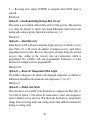
Option 01 — Equipment Type
Option 02 — Clean Filter Timer Adjustment
Option 03* — Fahrenheit/Centigrade Selection
Option 04 — Fan (G) on with W/W1 Selection
Option 05 — Room Air Temperature Sensing (programmable
models only)
Option 06 — Cooling Lockout Below 55F/13C Selection (only
available if outdoor air sensor is present)
Option 07 — Zoning
Option 08 — Auxiliary Heat Lockout Temperature Setting (only
available when heat pump is used and when
outdoor air temperature sensor is present)
Option 10 — Reversing Valve
Option 11 — Adjustable Setpoint Deadband
Option 12 — Smart Recovery (programmable models only)
Option 13 — Room Temperature Offset Adjustment
Option 15 — Enable Auto Mode
Option 16 — Cycles Per Hour
Option 17 — Time Between Stages
22
Option 18* —
Option 19 —
Option 20 —
Option 21* —
Option 24* —
Backlight Configuration
Dry Contact (programmable models only)
Outdoor Air Temperature Offset Adjustment
Keypad Lockout
Programmable/Non−Programmable
(programmable models only)
Option 25* — Number of Programmable Periods per Day
(programmable models only)
Option 26 — Minimum Cooling Setpoint
Option 27 — Maximum heating Setpoint
Option 28 — UV Light Reminder
Option 29 — Humidifier Pad Reminder
Option 30* — Programmable Fan (programmable models only)
Option 31* — Daylight Savings Time Configuration
(programmable models only)
Option 32 — Furnace Heat Staging
Option 33 — Single or Two−Piece Installation
Option 41 — Variable Speed Blower
Option 44 — Super Comfort Heat
Option 99 — Reset to Factory Defaults
TO ENTER CONFIGURATION MODE
Press and hold FAN button for approximately 10 sec. The Display Module is
now in configuration mode. It will automatically exit this mode if no button is
pressed for 3 minutes. Pressing either FAN or DONE button will exit
configuration mode immediately.
23
WHILE IN CONFIGURATION MODE
The option number is displayed in the heat setpoint location and the
configuration setting is displayed in the cool setpoint location. On the
T6−PAC/PHP (programmable) models, a box will surround the option number.
The mode button is used to move the box between the two displayed values. The
soft keys below the listed values may also be used to move the box between
selected values. The value inside the box is changed by using the UP/DOWN
buttons. On the T6−NAC/NHP (non−programmable) models, one of the values
will be flashing. The mode button is used to change which value is flashing or
the Home and Sleep buttons may also be used to select which value to flash. The
value that is flashing is changed by using the UP/Down buttons. All changes
made are saved at the time of selection and will be saved in the event of the 3
minute time−out or when installer exits from configuration menu.
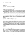
Configuration Options —Selection
Option 01 — Equipment Type
HP model — Range: HP, AC, H, C, H2, A2.
AC model — Range: AC, H, C.
HP — operates a single−speed heat pump with a fan coil.
AC — operates a single−speed AC.
H — operates a heat−only system. Furnace or fan coil only;
no outdoor unit.
C — operates a cool only−system. Outdoor AC unit with an
indoor fan coil with no strip heaters.
A2 — 2−stage air conditioner with a furnace or fan coil.
H2 — 2−stage heat pump with a fan coil.
24
Defaults
HP model defaults to HP.
AC model defaults to AC.
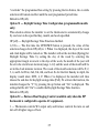
Option 02 — Clean Filter Timer
Select hours of blower operation (heating, cooling, or fan) before CHECK
FILTER icon is displayed. With OF selected, icon will never come on, disabling
this feature. Time selection can range from 800 to 7200 hr by selecting numbers
1 through 9. (Time is 800 X number selected.) Default is 4 (3200 hr).
Recommended selections are disposable filter−800 to 2400 hr, media filter−2400
to 3200 hr, or electronic air cleaner−1600 to 2400 hr of blower operation. For
higher efficiency filter, please consult filter’s Installation Instruction for details.
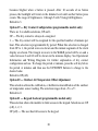
Option 03 — Fahrenheit/Centigrade
Select between Fahrenheit (F) and Centigrade (C) operation. Factory default is
Fahrenheit (F).
Option 04 — Fan (G) On With W/W1
This selection determines whether fan (G) output is to be On or OFF when any
W/W1 (furnace or strip heat) output is On. Most furnaces and fan coils manage
their own blowers and do not require separate G signal. For these applications,
select OFF. Some auxiliary heaters require separate G signal to turn on blower. In
this case, select On.
Default is OF (off).
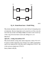
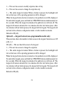
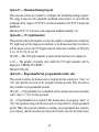
Option 05 — Room Air Temperature Sensing (programmable models only)
The remote room sensor may be installed as a single sensor or multiple sensors
may be installed for further averaging functionality. See Fig. 16
25
RRS
SRTN
Sensor 1
Sensor 2
Sensor 3
Sensor 4
A09130
Fig. 16 − Remote Room Sensor − Parallel Wiring
This selection determines which sensor the control will use for measuring room
air temperature. Room air temperature can be sensed in one of three ways; the
local sensor (L) located on the Display Module, the remote room air sensor (r),
or the average of local and remote sensors (Lr). Settings are L, r, Lr.
Default is L.
Option 06 — Cooling Lockout Below 55_F
This selection disables cooling when outdoor temperature is below 55F/13C.
It requires an outdoor temperature sensor. Setting is not available if valid outdoor
sensor is not connected. Set to OF (off) to allow cooling below 55F/13C. Set
to On to prevent cooling below 55F/13C.
Factory default is OF (off).
26
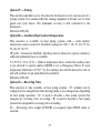
Option 07 — Zoning
This selection should be set to On when the thermostat is to be used as part of a
zoning system. It is assumed that the zoning equipment will take care of time
guard and cycle timers. The minimum on time is still controlled by the
thermostat.
Default is OF (off).
Option 08 — Auxiliary Heat Lockout Temperature
This selection is available on heat pump systems with a valid outdoor
temperature sensor connected. Available settings are: Off, 5, 10, 15, 20, 25, 30,
35, 40, 45, 50, 55.
OF (off) − function is disabled. Auxiliary heat is allowed to operate whenever
sufficient demand for heat is available.
5 to 55F (−15 to 13C) − Outdoor temperature above which the auxiliary heat
is not allowed to operate (unless MODE is set to Emergency Heat). If room
temperature falls below 45F (7C), the auxiliary heat will be allowed to turn on
and will continue to run until demand is satisfied.
Default is OF (off).
Option 10 — Reversing Valve
This selection is only available on heat pump systems. “O” terminal can be
configured to be energized in either heating mode or in cooling mode, depending
on heat pump operation. “O” is used to describe a heat pump system that
energizes its reversing valve in cooling. “B” is used to describe a heat pump
system that energized its reversing valve in heating.
H — Reversing valve output (O/W2/B) is energized when HEAT mode is
selected.
27
C — Reversing valve output (O/W2/B) is energized when COOL mode is
selected.
Default is C.
Option 11 — Deadband Setting Between Heat & Cool
This option is not available on Heat Only and Cool Only systems. This selection
is to allow the installer to choose how much differential exists between the
heating and cooling setpoints. Allowable selections are 1−6.
Default is 2.
Option 12 — Smart Recovery
Smart Recovery OF (off) means setpoints change precisely at setback recovery
time. Thirty, 60, or 90 selects the number of minutes recovery starts before
programmed recovery time. Recovery takes place smoothly during the selected
recovery time, ending at the recovery time and temperature which is
programmed. Not available with non−programmable thermostats or when
thermostat is configured as non−programmable.
Default is 90.
Option 13 — Room Air Temperature Offset Adjust
The number of degrees to be added to the displayed temperature to calibrate or
deliberately miscalibrate the measured room temperature ( −5 to +5).
Default is 0.
Option 15 — Enable Auto Mode
This selection is not available if the thermostat is configured as Heat Only or
Cool Only in Option 1. This allows the homeowner to select auto changeover
mode in addition to heat and cool. This allows the thermostat to automatically
change between heating mode and cooling mode when sufficient demand for
heating or cooling exists.
28
On — Auto mode is available.
OF — Auto mode is not available.
Default is On.
Option 16 — Maximum Cycles Per Hour
This selection limits the number of cycles per hour that the thermostat allows the
system to operate. Selections are 2, 4, 6.
2 — The heating and cooling outputs will be energized no more than 2 times per
hour. When an output is energized, it will not be energized again for 30 minutes.
4 — The heating and cooling outputs will be energized no more than 4 times per
hour. When an output is energized, it will not be energized again for 15 minutes.
6 — The heating and cooling outputs will be energized no more than 6 times per
hour. When an output is energized, it will not be energized again for 10 minutes.
Default is 4.
Option 17 — Time Between Equipment Stages
This selection is only available for heat pump systems. This determines the
minimum number of minutes of equipment operation on the highest compressor
stage before allowing the transition to auxiliary heat. Available selections are 10,
15, 20, and 25. The time between stages of any individual piece of equipment,
such as low speed and high speed compressor or fan coil stages, will be fixed at
10 minutes.
Default is 15.
Option 18 — Backlight Configuration
When OF (off), the backlight will be lit for 10 seconds after a button is pressed.
After 10 seconds of no button presses, the backlight turns off. When On, the
backlight will normally be on and dim in appearance. The backlight brightness
29
becomes brighter when a button is pressed. After 10 seconds of no button
presses, the backlight will return to the dimmer level until another button press
occurs. The range of brightness is 1 through 5 with 5 being full brightness.
Default is 3.
Option 19 — Dry Contact Configuration (programmable models only)
There are 2 available selections, OF and 1.
OF — The dry contact is always de−energized.
1 — The dry contact will be energized for the specified number of minutes per
hour. This selection is programmable by period. When this selection is changed
from OF to 1, the period icons are shown and the minute segments of the clock
display are shown. The triangle icon next to the WAKE period will be on and a
value between 0 and 60 will be shown in the minutes display. See Operational
Information and Wiring Diagrams for further explanation of dry contact
configuration and use. To change the period or minutes, press the soft key below
the period or minutes and then use the UP/DOWN buttons to change to the
desired value.
Default is OF (off).
Option 20 — Outdoor Air Temperature Offset Adjustment
This selection allows the calibration, or deliberate miscalibration of the outdoor
air temperature sensor reading. The selection ranges from −5 to +5.
Default is 0.
Option 21 — Keypad Lockout (programmable models only)
This selection allows the installer to limit access to the keypad. Selections are OF
(off), 1, 2, 3.
OF (off) — The user has full access to the keypad.
30
1 — The user has access to modify setpoints, time of day.
2 — The user has access to change the setpoints only.
3 — The entire keypad is locked. When a button is pressed, the backlight will
turn on but none of the operating parameters will be changed.
When the keypad lock selection is turned on, the padlock icon will be displayed.
To unlock the keypad, press and hold the UP/DOWN buttons simultaneously for
five seconds. When the keypad is unlocked, the padlock icon will turn off. The
keypad will remain unlocked for two minutes after the last button press. After
two minutes with no button presses, the keypad will lock again. The keypad will
not lock in the software configuration mode or in the installer test mode.
Default is OF (off).
Option 21 — Keypad Lockout (non−programmable models only)
This selection allows the installer to limit access to the keypad. Selections are OF
(off), 1, 2.
OF (off) — The user has full access to the keypad.
1 — The user has access to change the setpoints.
2 — The entire keypad is locked. When a button is pressed, the backlight will
turn on but none of the operating parameters will be changed.
When the keypad lock selection is turned on, the padlock icon will be displayed.
To unlock the keypad, press and hold the UP/DOWN buttons simultaneously for
five seconds. When the keypad is unlocked, the padlock icon will turn off. The
keypad will remain unlocked for two minutes after the last button press. After
two minutes with no button presses, the keypad will lock again. The keypad will
not lock in the software configuration mode or in the installer test mode.
Default is OF (off).
31
Option 22 — High Cool Latch Temperature (only available if outdoor
sensor is present)
An outdoor sensor is required for high cool latch feature.
This selection is only available when Option 1 is set to H2, A2, or h2 and when
Option 7 (zoning) is set to OF (off). Configuration settings are OF (off), 80, 85,
90, 95, 100, 105, 110, On.
OF (off) — Cooling always starts in low stage (Y1) and stages up to high stage
(Y1 and Y/Y2) when demand is sufficient and staging timer constraints have
been satisfied.
80 to 110F (27 to 43C) — Outdoor temperature above which both first and
second stages of the compressor are energized to satisfy all cooling demands.
When a cycle starts under a high cool latch, it will finish the cooling cycle on
high stage.
On — The Y1 and Y/Y2 outputs are simultaneously energized to satisfy all
cooling demands.
Default is OF (off).
Option 23 — High Heat Latch Temperature (only available if outdoor
sensor is present)
This selection is only available when Option 1 is set to H2, or h2 and Option 7
(zoning) is set to OF (off). Configuration settings are OF (off), 20, 25, 30, 35, 40,
45, 50, On.
OF (off) —Heating always starts in low stage (Y1) and stages up to high stage
(Y1 and Y/Y2) when demand is sufficient and staging timer constraints have
been satisfied.
20 to 50F (−7 to 10C) — Outdoor temperature below which both first and
second stages of the compressor are energized to satisfy all heating demands.
32
When a cycle starts under a high heat latch, it will finish the heating cycle on
high stage.
On — The Y1 and Y/Y2 outputs are simultaneously energized to satisfy all
heating demands.
Default is OF (off).
Option 24 — Programmable/Non−Programmable
This selection allows the installer to configure the thermostat as either
programmable or non−programmable. Selections are P, nP.
Default is P (programmable models only).
Option 25 — Number of Programmable Periods
This selection allows the installer to configure the thermostat for two or four
periods per day. Two periods is a common commercial application and four
periods is more common for residential. This selection is not available if Option
24 has been set to nP to configure the thermostat for non−programmable
operation.
2 — Periods DAY and SLEEP are available
4 — Periods WAKE, DAY, EVE, and SLEEP are available.
Default is 4.
Option 26 — Minimum Cooling Setpoint
This selection allows the installer to configure the minimum cooling setpoint that
the user is allowed to set. The range is based on the value of the adjustable
deadband Option 11, such that the minimum of the range is 50F/10C plus the
adjustable deadband and the maximum is 90F/32C.
Default is 52F/11C (based on the adjustable deadband default = 2).
33
Option 27 — Maximum Heating Setpoint
This selection allows the installer to configure the maximum heating setpoint.
The range is based on the adjustable deadband value Option 11, such that the
minimum of the range is 50F/10C and the maximum is 90F/32C minus the
deadband.
Default is 88F/31C (based on the adjustable deadband default = 2).
Option 28 — UV Light Reminder
This selection allows the installer to select the number of months after which the
UV Light icon will be displayed to indicate to the homeowner that it is time to
call the dealer to have the UV Lights replaced. Selections available are OF (off),
6, 12, 18, 24, 30, 36, 42, 48.
OF (off) — The UV Light reminder is turned off and will never be displayed.
6−48 — The number of months after which the UV Light reminder will be
displayed, “CHECK UV LIGHT”.
Default is OF (off).
Option 30 — Programmable Fan (programmable models only)
This selection allows the homeowner to program the fan selection to “Auto” or
“On” fan operation for each of the program schedule periods. This selection is
only available on programmable models.
OF (off) — Programmable fan is disabled and the homeowner must manually
select “Auto” or “On” for fan operation.
On — Programmable fan is enabled. The homeowner can program “Auto” or
“On” fan operation along with the heat and cool setpoints for each programmed
period. When the program schedule is running, the programmed heat setpoint,
cool setpoint, and fan selection for that period will be used. If the homeowner
34
“overrides” the programmed fan setting by pressing the fan button, the override
selection will remain in effect until the next programmed period time.
Default is OF (off).
Option 31 — Daylight Savings Time Configuration (programmable models
only)
This selection allows the installer to set the thermostat to automatically change
by one hour on the specified day, month, and week specified.
OF (off) — Daylight Savings Time Function disabled.
1,2 On — The first time the UP/DOWN button is pressed, the value of this
selection changes from OF (off) to 1. When 1 is displayed, the days of the week
and clock digits will be turned on. The installer will set the start date (Spring) for
Daylight Savings Time by setting the day of the week by selecting the
appropriate triangle icon next to the days of the week, the month of the year will
be set in the clock hours location (range 1−12) and the week of the month will be
set in the clock minutes location. The week of the month selections will be F, 2,
3, 4, and L for First, 2nd, 3rd, 4th, and Last. So for the first Sunday in April, the
display would show SUN, 4, F. When 2 is displayed, the installer will then
choose the end date for daylight savings time (Fall). To activate the function, the
installer changes the “2” by pressing the up button and “On” is displayed. The
setting shall be left “On” to enable the Daylight Savings Time function.
Default is OF (off).
Option 32 — Furnace Heat Staging Control (available only when the HP
thermostat is configured to operate AC equipment).
1 — Thermostat controls W1 output only and furnace controls the turn on and
turn off of higher stages of heat.
35
2 — Thermostat will control the W1 and O/W2/B outputs.
Default is 1.
Option 33 — Single or Two−Piece Installation
This configuration allows the thermostat to compensate for the amount of heat
generated by the thermostat electronics to allow more accurate sensing of the
temperature sensor. The amount of heat compensation will be different between
single installation and two−piece installation.
Range: 1P or 2P
1P — The installation is single piece.
2P — The installation is two separate pieces.
Default is 2P.
Option 41 — Variable Speed Blower
This selection allows the installer to select between a single speed or variable
motor.
Off − The system has a single speed (PSC) blower.
On − The system has a variable speed blower.
Factory default is OF (Off)
Option 44 — Super Comfort Heat
This option is only available on heat pump units HP (HP, H2) when Option 41
(Variable Speed Blower) is set to On and the system has a valid OAT sensor.
OF (Off) − Comfort Heat is off
On − Comfort Heat feature is on.
If the outdoor air temperature is between 12 to 40F (−11 to 4C) and the
compressor is running in heating, then the fan output is turned off. This will
signal the variable speed blower to reduce the air speed. The fan output is turned
36
off even if the user has the fan selection set to continuous fan. The fan output
will be turned back on in this temperature range if the maximum capacity of
auxiliary heat is on due to system demand (auxiliary heat on in response to a
defrost signal shouldn’t cause the fan to turn back on).
If the outdoor air temperature is below 12F/−11C and there is sufficient
demand for the equipment to be on, then the fan output is turned back on and the
W/W1 output is energized. In a two speed unit the Y/Y2 output should be
energized in addition to the W/W1 output.
NOTE: All temperature boundaries have a +/− 2 hysteresis.
Factory default is OF (Off).
Option 99 — Reset to Factory Defaults
Use this capability to reset the stat to “out of the box” conditions. BEWARE! All
configuration settings, program settings, clock, and calendar which have been
manually entered will be lost!
When this option is selected, the configuration number (99), will appear on the
left and 10 will appear on the right. To perform the reset, first use the MODE key
to move the box from the 99 to the 10 (programmable model) or to flash the 10
(non−programmable model). Then press and hold the DOWN key. The 10 will
start counting down toward zero. If the DOWN key is kept pressed until the
count reaches zero, the reset will be performed. When the value reaches zero, the
heat setpoint shall display −−. The cool setpoint shall display − and the room air
temperature shall display Fd. When the factory defaults have been restored, the
thermostat will act as if power was cycled and return to normal operation. If the
DOWN key is released early, the number will return to 10 and the reset will not
occur.
37
SYSTEM START−UP AND CHECKOUT
The AC/HP Control is designed with a built−in installer test capability. It allows
easy operation of equipment without delays or setpoint adjustments to force
heating or cooling. To enable installer test mode, press and hold the fan button
for 15 seconds. After 10 seconds, the thermostat will enter Configuration Mode.
Continuing to hold the Fan button through 15 seconds will cause the thermostat
to enter Installer Test Mode. Pressing the Mode button will change the system
operating mode to test the heating and cooling equipment. Auto Mode is not
available during Installer Test Mode. If no buttons are pressed for 15 minutes, the
installer test mode will be terminated. Pressing DONE at any time will exit
installer test mode.
Heat − The first stage of heating will be energized for three minutes, then the first
and second stages (if a second stage exists) will turn on for an additional three
minutes. During the first stage of heating, the HEAT ON icon will be displayed.
The “auxiliary heat on” icon will be displayed if the second stage is electric heat
(HP unit type). For heat pump installation, only 1 stage of auxiliary heat is
available. Any staging of auxiliary heat must be managed by the furnace or fan
coil. At the end of the equipment cycle the MODE will return to OFF. The
display will count down from 180 seconds to 0 for each stage when the
equipment is energized. The test of a heating or cooling cycle can be terminated
before the timer expires by pressing the MODE button and changing the system
mode to OFF.
Installer test for cooling is the same as described for heating above. COOL ON
will be displayed during cooling in Installer Test Mode. In a heat pump
application, when the mode is set to “em heat” the auxiliary heat will turn on for
3 minutes. The clock display will count down from 180 to 0 during this test.
38
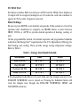
TO TEST FAN
Fan button switches FAN icon between AUTO and On. While On is displayed,
G output will be energized, turning fan on. On some fan coils, fan continues to
operate for 90 sec after G signal is removed.
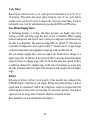
Final Settings
Be sure to press DONE to exit installer setup mode. If the system is to be left in
operation after installation is complete, use MODE button to select between
HEAT, COOL, or AUTO to provide desired operation of heating, cooling, or
auto.
On the programmable models, the default setpoints and programmed schedule
conform to the Energy Star requirements of the U.S. Department of Energy for
both heating and cooling. These provide energy saving temperature settings.
Refer to Table 1.
Table 1 – Energy Star Default Schedule
SCHEDULE
HEAT
COOL
Wake 6:00 AM
68F/20C
78F/26C
Day 8:00 AM
60F/16C
85F/29C
Evening 5:00 PM
68F/20C
78F/26C
Sleep 10:00 PM
60F/16C
82F/28C
If the programmed schedule is to be used, make sure the triangle icon next to the
FOLLOW SCHEDULE icon is turned on. Pressing the Schedule button will
cycle the triangle icon through the FOLLOW SCHEDULE, HOLD and
VACATION selections.
39
If fixed temperatures are desired, use SCHEDULE button to turn on arrow icon
next to HOLD. This will maintain setpoints, not allowing them to change with
programmed schedule.
The FAN button may be used to select between AUTO (fan on only with
equipment) and On (fan on continuously) fan modes. For further information on
temperature selection and programming, refer to Homeowner’s Guide.
Setting The Clock, Calendar, Daily Schedule, and Vacation
Settings (programmable models only)
To set the clock, press the SET button once. The Clock will be displayed at the
bottom center of the screen. Use the soft keys to move the box around the digits
to be set and the UP/DOWN buttons to change the setting. Concurrent presses of
the set button will cycle through the calendar, daily schedule, and vacation
settings.
Calendar may be changed by using the soft keys to select the Month, Day, or
Year. The UP/DOWN buttons are used to change the Month, Day, or Year setting
when the box surrounds it. Day of the week (Mon−Sun) is determined by
calendar settings and is not directly adjustable.
When changing daily schedule settings, the soft keys are used to set the days,
period times, heating setpoints, and cooling setpoints. The UP/DOWN buttons
are used to change the setting with the box around it. ALL PROGRAM
PERIODS (WAKE, DAY, EVE, SLEEP) MUST OCCUR WITHIN THE SAME
24 HOUR PERIOD.
When changing Vacation settings, the soft keys are used to choose the selection
to be adjusted and the UP/DOWN buttons are used to change the setting.
40
Vacation (programmable models only)
A vacation selection is available specifically for times where the home will not
be occupied for an extended period. Vacation mode has an automatic hold,
meaning that setpoints are not affected by the programmed schedule. Vacation
mode is active for a specified period of time. While in vacation mode, the system
provides temperature protection for the home in the selected mode, but not
comfort. When vacation mode is active, an arrow will be displayed beside
“VACATION” in the upper left corner of the display.
Vacation Setpoints
A special set of temperature setpoints exist which are active in vacation mode.
They are adjustable by the homeowner, are exclusively for vacation mode, and
are remembered from one vacation selection to the next. See Table 2 for default
values.
Table 2 – Vacation Setpoints Default Values
MODE
Fan
Heat Setpoint
Cool Setpoint
AUTO
Auto
55F/13C
85F/29C
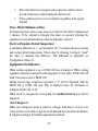
OPERATIONAL INFORMATION
Timers
Five−Minute Compressor Timeguard
This timer prevents compressor from starting unless it has been off for at least 5
minutes. It can be overridden for 1 cycle by simultaneously pressing FAN and
UP buttons.
41
Cycle Timer
Based on the selection of 2, 4, or 6 cycles per hour, this timer is set to 30, 15, or
10 minutes. This much time must elapse from the start of one cycle before
another cycle can start. It serves to impose the cycles per hour limits. It can be
defeated for one cycle by simultaneously pressing the FAN and UP buttons.
Ten−Minute Staging Timer
In multistage heating or cooling, this timer prevents any higher stage from
turning on until preceding stage has been on for 10 minutes. When staging
between compressor and electric heat or between compressor and furnace heat,
the time is configurable. The timer is configurable via Option 17. This timer is
overridden if temperature error is greater than 5 (usually due to a large change
in desired temperature) and equipment stages up in 60 second intervals.
The ten−minute staging timer does not require the thermostat to change to a
higher stage after 10 minutes. If the system is able to meet the demand (maintain
setpoint) it may not change stages after the 10 minute timer has expired. If there
is sufficient demand for a higher stage at the end of 10 minutes or at any time
after the 10 minute timer has expired, the thermostat will energize the next higher
stage.
Defrost
Detection of defrost will not work properly if the installer has configured the
O/W2/B output to function as a B output. During heat pump heating, a defrost
signal shall be considered valid if the compressor output is energized and the
defrost signal has been active for less than 15 consecutive minutes. Any defrost
signal present for longer than 15 minutes shall be considered invalid.
Heat pump/fan coil systems shall use this input to:
42
Detect that defrost is in progress and energize the auxiliary heat to
provide homeowner comfort during the defrost cycle
Allow a defrost cycle to run to completion regardless of the system
demand
Three−Minute Minimum on Time
In normal operation, when a stage turns on, it will not turn off for a minimum of
3 minutes. If the setpoint is changed, this timer is canceled, allowing the
equipment to turn off immediately when the demand is removed.
Heat/Cool Setpoints (Desired Temperature)
A minimum difference of 1 and maximum of 6 is enforced between heating
and cooling desired temperatures. This is done by allowing 1 setting to “push”
the other, to maintain this difference. This difference is adjustable via
Configuration Option 11.
Equipment On Indicators
When cooling equipment is on, a COOL ON icon is displayed. While cooling
equipment operation is delayed by the timeguard or cycle timer, COOL ON will
flash. The same is true for HEAT ON.
During second stage compressor operation a “2” will be displayed with the
HEAT ON or COOL ON icon. This is displayed when the thermostat is
configured as H2, A2, or h2.
When the W is energized in a heat pump, the auxiliary heat on icon will be
displayed.
Auto Changeover
When auto changeover mode is selected, a change from heat to cool (or vice
versa) will not occur until an opposite mode demand has existed for 20 minutes.
If setpoint is changed, 20−minute requirement is deleted.
43
Emergency Heat Mode
When AC/HP Control is configured as a heat pump and emergency heat is
selected, all Y signals are locked out, and W becomes energized upon a call for
heat.
Programmable Fan (programmable models only)
The fan output can be programmed based on period of the day. When
programming for each day and period the fan can be set to On or AUTO. If the
fan button is pressed to change from On to Auto or vice versa when
programmable fan has been enabled, the manual change will only remain in
effect until the next program period, when the programmable fan setting will be
changed per the scheduled setting.
Dry Contact
On the programmable models, the dry contact that can be used for control of an
auxiliary device. The dry contact may be configured to be closed for a specific
number of minutes per hour for each period of the program schedule. This can
be used to operate a ventilator, damper, system blower, or other auxiliary device.
There are two terminals, D1 and D2.
If it is desired to operate a ventilator or other device, the D1 and D2 terminals
can be connected directly to the equipment. This will provide a closed contact
for the specified number of minutes per hour. See Option 19.
If timed control of the system blower is required, the dry contact can be used for
this function. The G terminal can be connected to one of the dry contact
terminals with the other terminal being connected to Rc and/or Rh for timed
control of the fan. Note that this is not the same as programmable fan Option 30.
See Wiring Diagrams for more information.
44
Relays
This thermostat uses latching relays. When the thermostat loses power, the relays
will remain in their last position until power is restored and all relays are reset to
their correct position. Out of the box, the outputs may appear to be On when the
thermostat is not powered. This is normal. Output states should only be checked
when the thermostat is powered.
Temperature Offset After Power Cycle
To compensate for internal heat build−up from the electronics in the thermostat,
the thermostat will add an offset to the actual temperature that it measures. If the
thermostat power is cycled quickly, one can witness an immediate increase in the
actual temperature displayed due to this added offset. The thermostat display will
return to the actual room temperature after several minutes of operation.
TROUBLESHOOTING
If the display module doesn’t power up after power is applied, check the Rc/Rh
and C terminals for 24VAC. If 24VAC is present, check the voltage between Vg
and V+. This voltage will be approximately 12−20VDC. If voltage is present,
check the polarity to make sure it is wired correctly. The display will not power
up if polarity is reversed.
If dashes appear for Option 01 in config and during reboot, the problem could be
the red pigtail being wired to Rc or Rh and the black pigtail being wired to C. If
so, remove the two−wire pigtail and connect to the V+ and Vg terminals.
Error Codes
“−−” − If AC/HP Control cannot properly read room temperature, display will
indicate “−−” and all outputs (except fan, if on) will turn off. In the case where
the installer has selected to average the local sensor and the remote room sensor,
the AC/HP display will alternate between “−−” for the failed sensor and the
45
temperature sensed by the working sensor every 10 seconds. The control will
operate from the temperature sensed by the working sensor.
E1 − If the Display Module and the Equipment Control Module cannot
communicate via two−wire connection, an E1 will be displayed.
E2 − There is no E2 error message.
E3 − If AC/HP Control cannot properly read outdoor temperature, and it is
needed for proper operation, display will indicate “−−” in the outdoor
temperature location.
E4 − If AC/HP Control’s internal memory fails, E4 will be displayed. Replace
AC/HP Control.
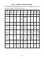
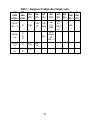
Table 3 can be used as a troubleshooting tool for determining which outputs will
be active for a particular configuration and each operating mode.
When replacing a failed component such as an equipment control module or a
display module, the installer should replace both parts as a matched set. It is very
easy to accidentally mix an A/C or HP display with a PAC equipment control
module. When this happens, some functions appear in the setup while others do
not. This can be very confusing to troubleshoot. Verify that both parts have the
same model and serial number when troubleshooting the thermostat.
46
Table 3 – Equipment Configuration Outputs
For COOL, HEAT and Emergency Heat modes, the following chart shows the
state for each output in each stage of operation
EQUIP
CONFIG
OPTION 01
HARDWARE
CONFIG
COOL
STG 1
COOL
STG 2
HEAT
STG 1
HEAT
STG 2
HEAT
STG 3
HEAT
STG 4
EM
HEAT
STG 1
EM
HEAT
STG 2
SS AC
AC
Y/Y2
-
W/W1
-
-
-
-
-
-
-
-
-
SS AC
HP
2S
Y/Y2
-
W/W1
W/W1
O/W2/B
(if
Opt32+2)
SS HP
RVS + O
HP
Y/Y2,
O/W2/B
-
Y/Y2
Y/Y2,
W/W1
-
-
W/W1
-
SS HP
RVS + B
HP
Y/Y2
-
Y/Y2,
O/W2/B
Y/Y2,
W/W1,
O/W2/B
-
-
W/W1
-
SS HP
RVS + O
Opt43 = On
2S
Y/Y2,
O/W2/B
-
Y/Y2
Y/Y2,
W/W1
Y/Y2
Y1/W2
Y/Y2
W/W1
Y1/W2
W/W1
W/W1
Y1/W2
SS HP
RVS + B
Opt43 = On
2S
Y/Y2
-
Y/Y2,
O/W2/B
Y/Y2,
W/W1,
O/W2/B
Y/Y2,
Y1/W2,
O/W2/B
Y/Y2,
Y1/W2,
W/W1
O/W2/B
W/W1
W/W1
Y1/W2
2SPD AC
2S
Y1/W2
Y/Y2,
Y1W2
W/W1
W/W1
O/W2/B
-
-
-
-
2SPD HP
RVS + O
2S
Y1/W2
O/W2/B
Y1/W2
Y/Y2
O/W2/B
Y1/W2
Y1/W2
Y/Y2
Y1/W2
Y/Y2
W/W1
-
W/W1
-
47
Table 3 − Equipment Configuration Outputs (cont.)
EQUIP
CONFIG
OPTION 01
HARDWARE
CONFIG
COOL
STG 1
COOL
STG 2
HEAT
STG 1
HEAT
STG 2
HEAT
STG 3
HEAT
STG 4
EM
HEAT
STG 1
EM
HEAT
STG 2
2SPD HP
RVS + B
2S
Y1/W2
Y1/W2
Y/Y2
Y1/W2
O/W2/B
Y1/W2
Y/Y2
O/W2/B
Y1/W2
Y/Y2
O/W2/B
W/1
-
W/W1
-
Heat Only
Unit
AC
HP
2S
-
-
W/W1
If HP or
2S board
AND
Opt32 + 2
-
-
-
-
2S
Y1/W2
Y1/W2
Y/Y2
-
-
-
-
-
-
AC
HP
Y/Y2
-
-
-
-
-
-
-
Cool Only
Unit
Cool Only
Unit
48
WIRING DIAGRAMS
Display module
Display module wall mount
Equipment Control Module
V+
Fan Coil
Heat Pump
V+
O
O
V+
Vg
V+
RVS/Heat Stage 2
Vg
O/B W2
W3
W2
Vg
Vg
Heat Stage 1
W/W1
W2
Compressor
Y/Y2
Y
Not Used
Y1
Y
Fan
G
G
24VAC Hot Heating
Rh
R
R
24VAC Hot Cooling
Rc
Dry Contact 1
D1
Dry Contact 2
D2
24VAC Common
C
COM
COM
Outdoor Air Temp
OAT
Remote Room Sensor
RRS
Outdoor Sensor *
OAT/RRS Com
OAT/RRS
Remote Room
Sensor *
* Indicates connection may not be required/available.
A09174
Fig. 17 − Display to Equipment Control Module Connection
49
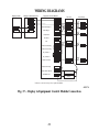
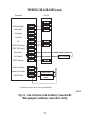
WIRING DIAGRAMS(cont.)
Thermostat
Fan Coil
Heat Pump
O
RVS/Heat Stage 2
O/B W2
W3
Heat Stage 1
W/W1
W2
Compressor
Y/Y2
Y
Not Used
Y1
O
W2**
Y
Fan
G
G
24VAC Hot Heating
Rh
R
R
24VAC Hot Cooling
Rc
Dry Contact 1
D1
Dry Contact 2
D2
24VAC Common
C
COM
COM
Outdoor Air Temp
OAT
Remote Room Sensor
RRS
Outdoor Sensor *
OAT/RRS Com
OAT/RRS
Remote Room
Sensor *
* Indicates connection may not be required/available.
** Some heat pumps may designate W1.
A09154
Fig. 18 − Fan Coil with Heat Pump (HP Thermostat)
50
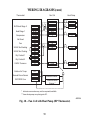
WIRING DIAGRAMS(cont.)
Thermostat
Fan Coil
O
RVS/Heat Stage 2
O/B W2
W3
Heat Stage 1
W/W1
W2
Compressor
Y/Y2
Not Used
Y1
Fan
G
G
24VAC Hot Heating
Rh
R
24VAC Hot Cooling
Rc
Dry Contact 1
D1
Dry Contact 2
D2
24VAC Common
C
Aux. Connection
COM
Outdoor Air Temp
OAT
Remote Room Sensor
RRS
Outdoor Sensor *
OAT/RRS Com
OAT/RRS
Remote Room
Sensor *
* Indicates connection may not be required/available.
A09155
Fig. 19 − Fan Coil shown with Auxiliary Connection #1
51
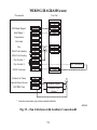
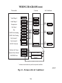
WIRING DIAGRAMS(cont.)
Thermostat
Fan Coil
Air Conditioner
O
RVS/Heat Stage 2
O/B W2
W3
Heat Stage 1
W/W1
W2
Compressor
Y/Y2
Y
Not Used
Y1
Y
Fan
G
G
24VAC Hot Heating
Rh
R
R
24VAC Hot Cooling
Rc
Dry Contact 1
D1
Dry Contact 2
D2
24VAC Common
C
COM
COM
Outdoor Air Temp
OAT
Remote Room Sensor
RRS
Outdoor Sensor *
OAT/RRS Com
OAT/RRS
Remote Room
Sensor *
* Indicates connection may not be required/available.
A09175
Fig. 20 − Fan Coil with Air Conditioner
52
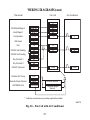
WIRING DIAGRAMS(cont.)
Thermostat
Fan Coil
O
RVS/Heat Stage 2
O/B W2
W3
Heat Stage 1
W/W1
W2
Compressor
Y/Y2
Not Used
Y1
Fan
G
G
24VAC Hot Heating
Rh
R
24VAC Hot Cooling
Rc
Dry Contact 1
D1
Dry Contact 2
D2
24VAC Common
C
Aux. Connection
COM
Outdoor Air Temp
OAT
Remote Room Sensor
RRS
Outdoor Sensor *
OAT/RRS Com
OAT/RRS
Remote Room
Sensor *
* Indicates connection may not be required/available.
A09156
Fig. 21 − Fan Coil shown with Auxiliary Connection #2
(Heat pump/air conditioner removed for clarity)
53
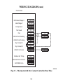
WIRING DIAGRAMS(cont.)
Thermostat
Furnace
* Heat Stage 2
O/B W2
W2*
Heat Stage 1
W/W1
W/W1
Compressor
Y/Y2
Y/Y2
Not Used
Y1
Air Conditioner
Y
Fan
G
G
24VAC Hot Heating
Rh
R
R
24VAC Hot Cooling
Rc
Dry Contact 1
D1
Dry Contact 2
D2
24VAC Common
C
COM
COM
Outdoor Air Temp
OAT
Remote Room Sensor
RRS
Outdoor Sensor *
OAT/RRS Com
OAT/RRS
Remote Room
Sensor *
* Indicates connection may not be required/available.
A09157
Fig. 22 − Furnace with Air Conditioner
54
WIRING DIAGRAMS(cont.)
Thermostat
RVS/Heat Stage 2
O/B W2
Heat Stage 1
W/W1
Compressor
Y/Y2
Not Used
Y1
Fan
G
G
24VAC Hot Heating
Rh
R
24VAC Hot Cooling
Rc
Dry Contact 1
D1
Dry Contact 2
D2
24VAC Common
C
Outdoor Air Temp
OAT
Remote Room Sensor
RRS
OAT/RRS Com
OAT/RRS
C
A09158
Fig. 23 − Thermostat with Dry Contact Control for Run Time
55
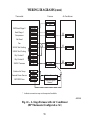
WIRING DIAGRAMS(cont.)
Thermostat
Furnace
Air Conditioner
W2
RVS/Heat Stage 2
O/B W2
Heat Stage 1
W/W1
W/W1
Compressor
Y/Y2
Y/Y2
Not Used
Y1
Y
Fan
G
G
24VAC Hot Heating
Rh
R
R
24VAC Hot Cooling
Rc
Dry Contact 1
D1
Dry Contact 2
D2
24VAC Common
C
COM
COM
Outdoor Air Temp
OAT
Remote Room Sensor
RRS
Outdoor Sensor *
OAT/RRS Com
OAT/RRS
Remote Room
Sensor *
* Indicates connection may not be required/available.
A09159
Fig. 24 − 2−Stage Furnace with Air Conditioner
(HP Thermostat Configured as AC)
56
WIRING DIAGRAMS(cont.)
Single-Stage
Furnace
Thermostat
RVS/Heat Stage 2
O/B W2
Heat Stage 1
W/W1
Compressor Low
Y1
Compressor High
Y/Y2
Y/Y2
Fan
G
G
24VAC Hot Heating
Rh
R
24VAC Hot Cooling
Rc
Dry Contact 1
D1
Dry Contact 2
D2
24VAC Common
C
Single-Stage
Air Conditioner
W/W1
Y
R*
COM
Outdoor Air Temp
OAT
Remote Room Sensor
RRS
Outdoor Sensor *
OAT/RRS Com
OAT/RRS
Remote Room
Sensor *
COM
* Indicates connection may not be required/available.
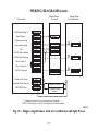
NOTE: Rc/Rh jumper is cut on the Equipment Control Module.
A09160
Fig. 25 − Single−stage Furnace with Air Conditioner and Split Power
57
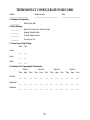
THERMOSTAT CONFIGURATION RECORD
Installer
_________________________
Model Number
______________________________
Date
_________________________
A. Hardware Configuration
__________
Seal Hole In Wall
B. Mode Settings
__________
Mode (Off, Heat, Cool, Auto, Em Heat)
__________
Heating Setpoint Value
__________
Cooling Setpoint Value
__________
Fan (Auto or On)
C. Home, Away, Sleep Settings
Home
Away
Sleep
Heat
Cool
____
____
____
____
____
____
D. Schedule (For Programmable Thermostats)
Period 1
All Days
Weekdays
Weekend
Period 2
Period 3
Period 4
Time
Heat
Cool
Time
Heat
Cool
Time
Heat
Cool
Time
Heat
Cool
____
____
____
____
____
____
____
____
____
____
____
____
____
____
____
____
____
____
____
____
____
____
____
____
____
____
____
____
____
____
____
____
____
____
____
____
58
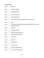
E Configuration Options
Option 01
Option 02
Option 03*
Option 04
Option 05
Option 06
Option 07
Option 08
Option 10
Option 11
Option 12
Option 13
Option 15
Option 16
Option 17
Option 18*
Option 19
Option 20
_____
_____
_____
_____
_____
_____
_____
_____
_____
_____
_____
_____
_____
_____
_____
_____
_____
_____
Equipment Type
Clean Filter Timer Adjustment
Fahrenheit/Centigrade Selection
Fan (G) on with W/W1 Selection
Room Air Temperature Sensing
Cooling Lockout Below 55F Selection (only available if outdoor air sensor is present)
Zoning
Auxiliary Heat Lockout Temperature Setting (only available when heat pump is used and when outdoor air
temperature sensor is present)
Reversing Valve
Adjustable Setpoint Deadband
Smart Recovery (programmable models only)
Room Air Temperature Offset Adjustment
Enable Auto Mode
Cycles Per Hour
Time Between Stages
Backlight Configuration
Dry Contact (programmable models only)
Outdoor Air Temperature Offset Adjustment
59
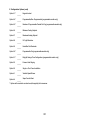
E Configuration Options (cont)
Option 21*
Option 24*
Option 25*
Option 26
Option 27
Option 28
Option 29
Option 30*
Option 31*
Option 32
Option 33
Option 41
Option 44
_____
_____
_____
_____
_____
_____
_____
_____
_____
_____
_____
_____
_____
Keypad Lockout
Programmable/Non-Programmable (programmable models only)
Number of Programmable Periods Per Day (programmable models only)
Minimum Cooling Setpoint
Maximum Heating Setpoint
UV Light Reminder
Humidifier Pad Reminder
Programmable Fan (programmable models only)
Daylight Savings Time Configuration (programmable models only)
Furnace Heat Staging
Single or Two-Piece Installation
Variable Speed Blower
Super Comfort Heat
* Options with an asterisk can also be set/changed by the homeowner.
60
2009 Bryant Heating & Cooling Systems 7310 W. Morris St. Indianapolis, IN 46231
Printed in U.S.A.
Edition Date: 06/09
Catalog No:
Manufacturer reserves the right to change, at any time, specifications
and designs without notice and without obligations.
IIT6-PAC-03
Replaces: IIT6-PAC-02
2