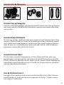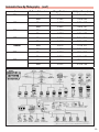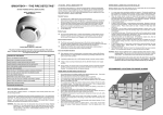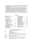
1
ETRS
Congratulations on your choice of the Zenza Bronica ETRS single lens reflex camera, which
will offer you high quality performance, handling convenience and versatility required for
professional photography. The Zenza Bronica ETRS has been developed as a "system" camera, with a very high degree of interchangeability. The Zenza Bronica ETRS is backed up by a
full range of valuable accessories, which permit use in many other day-to-day assignments,
which require a fast-handling camera with complete exposure automation.
Although instructions described in this booklet are based on a standard combination consisting of the ETRS main camera body with standard Zenzanon-EII 75mm lens, Film Back
ETRS 120 and Waist-level finder E, these lenses, film back and finder are left to your discretion to select such items best suited for your picture taking. To get best results from your
camera, we suggest that you read this instruction manual carefully, before you even touch
the camera.
1
Contents
Specifications of the ZENZA BRONICA ETRS
Parts of the ZENZA BRONICA ETRS
1.
2.
3.
4.
5.
6.
7.
8.
9.
10.
11.
12.
13.
14.
15.
16.
17.
18.
19.
20.
21.
22.
23.
24.
25.
26.
27.
28.
29.
Loading the Battery
Battery Checking
Attachment and Removal of Film Backs
Construction of Film Back
Film Loading
Film Type Indicator Frame
Film Advance and Shutter Cocking
Exposure Counter
Film Unloading
Setting the Shutter Speed Dial
Shutter Release Button
Time (T) Exposure
Exchanging Lenses
Interchanging Lenses
Waist-Level Finder and Interchanging Magnifiers
Setting the Aperture
Focusing Adjustment
Distance Scale and Depth of Field Scale
Infrared Photography
Flash Photography
Multiple Exposures
Interchanging Focusing Screens
Attachment of Neck Strap
Facts about the Battery
Pointers on Shooting
Care and Maintenance
Depth of Field Tables
Interchangeable Lenses
Accessories for Increasing the Versatility
Page
3, 4
5
6
6
6, 7
7, 8
8, 9, 10
10
10
10
11
11
12
13
13
14
14, 15
15
16
16
17
17
17
18
18, 19
19
20
20, 21
22
23, 24
25
2
Specifications of the ZENZA BRONICA ETRS
Type
4.5cm x 6cm format lens shutter single reflex camera,
with interchangeable lens, film back, finder and
focusing screen systems.
Frame Size
42.5mm x 55.1mm (side/length ratio of 1:1.29 closely
matches standard paper and reproduction sizes.)
Film
120 roll film (15 exposures); 220 roll film (30 exposures); 135 cartridge loaded film; and Polaroid® Land
pack films. (Exclusive film backs for each film type)
Standard Lens
Zenzanon-EII 75mm F2.8, interchangeable type; 6
elements in 4 groups; multi-layer anti-reflection coated; 49° angle of view, F22 minimum aperture, helical
focusing from inf. to 60cm.
Filter Size
Ø62mm for 4-250mm lenses and Ø95mm for 500mm
lens.
Lens Mount
Exclusive four claw Bronica ETR bayonet mount.
Lens Diaphragm
Fully automatic instant re-opening lens diaphragm
action; equal-distant aperture scale graduations;
depth of field previewing.
Shutter
Electronic control SEIKO #0 between-lens leaf shutter; shutter speeds 8 sec. to 1/500 sec. plus T (time
exposures); intermediate settings are not possible,
mechanical control setting 1/500 sec.
Multiple Exposure
Multiple exposures possible with lever on main body.
3
Specifications of the ZENZA BRONICA ETRS
(con’t)
Film Back
Daylight loading interchangeable type; Exclusive film
backs for 120, 220, and 135 cartridge loaded films
and Polaroid® pack film.
Finder System
Interchangeable finder system, with choice of five
optional finders or Waist-Level Finder E, AE (automatic exposure)-II finder E, Rotary Viewfinder E, Prism
Finder E and Sports Finder E. (No standard finder is
supplied and, therefore, a suitable one must be
ordered separately.)
Focusing Screen
Interchangeable type. Standard screen has diagonally-oriented split-image rangefinder spot surrounded
by microprism ring and full-area matte screen. For
optional screens, please see 22. Interchanging
Focusing Screens.
Flash Synchronization
X-setting (up to 1/500 sec.)
Battery Checking
Red-colored LED lights up within screen area when
battery check button is depressed, if there is sufficient power; also LED flash signals upon closing of
shutter blades.
Battery
Single 6-volt silver oxide or alkaline battery also
powers AE-II finder E, when attached.
Dimensions
91 (wide) x 107 (high) x 165 (long) mm (With
Zenzanon-EII 75mm lens, Film Back ETRS 120 and
Waist-Level Finder E.)
Weight
465 grams (ETRS Main body only; without battery)
1,280 grams (With Zenzanon-EII 75mm lens, Film
Back ETRS 120 and Waist Level Finder E; without battery.)
4
Parts of the ZENZA BRONICA ETRS
Flash synch socket
Aperture ring
Depth of field scale
Distance scales
Focusing ring
Lens alignment dot
Focusing
hood/magnifier
catch
Waist-level finder
Shutter speed dial
Shutter speed scale
Magnifier
Finder release button
Back cover
release button
(left)
Shutter release button
Back cover
release button
(right)
Exposure counter
Depth of field
preview lever
Multiple exposure lever
Neck strap stud
Battery check button
Film winding crank
Dark slide slit
Film plane mark
Manual film winder
Flash synch contact
Speed Grip
shutter
release
connection
Motor drive contacts
Shutter release button
locking ring
Lens release button
Cable
release
socket
Film back release
button
Spool holders
Neck strap stud
T (Time)
exposure lever
Setscrew
Film type indicator frame
Tripod mounting shoe
Tripod socket
(1/4” screw)
Battery chamber cover
Battery chamber button
5
1. Loading the Battery
The electronically controlled shutter will not work without loading the battery.
The shutter will be mechanically controlled when the battery is not loaded or when it is
loaded with its polarity marks reserved. It will then be released at 1/500 sec., regardless of
the setting on the shutter speed dial.
Your camera is supplied with an alkaline battery. For longer performance we recommend a
silver oxide battery (Eveready No. 544, UCAR No. 544 or Duracell No. PX-28.)
A. Depress the battery chamber button with your finger and at the
same time, move the battery chamber cover in the arrow-indicated
direction. The cover will come off easily.
B. Coincide the plus (+) and minus (-) marks on the battery with similar
polarity indications in the battery chamber. Then, push the negative
end of the battery first and follow with the positive end. Insert the
BATTERY end of the battery chamber cover, which also has a mark
coinciding to that on the body. Then move the cover in the other
direction (opposite to the arrow indication) until it locks in place.
2. Battery Checking
If a red colored LED lights up in the left-rear corner (of the waist-level
finder) when the battery check button is pressed, the battery is loaded
properly and there is sufficient power for electronic operations.
* If the LED does not light up, (1) the battery is not loaded properly or
(2) it is completely drained.
3. Attachment and Removal of Film Back
The film back is a film chamber that can be attached or detached freely, thus permitting free
exchange of film types even during shooting sessions.
The camera main body and film back are fully coupled, upon connection. Therefore, always
turn the film-winding crank completely one time, upon attaching the film back. If winding is
not possible, all preparations for taking pictures have been completed. But, if winding is
possible, rotating the film winding crank until it stops will automatically take care of the
incomplete action, whether un-cocked shutter or film not advanced. Thus, it's always possible to choose the film type most suited for the shot, even midway in the roll.
6
3. Attachment and Removal of Film Back
(con’t)
* Make full use of the interchangeable film back.
1. Color and black-and-white in different film speeds can be shot, as required.
2. Continuous shooting is possible if sufficient preloaded film backs are available.
3. Don't waste unsuitable film used in a previous session but simply load up a new film
back with the required film type.
4. Many in the studio or at home can use a single ETRS main body, by using additional film
backs.
A. To attach the film back to the main body, simply insert the latches at
the upper end of the film back into the attachment openings at the
upper end of the main body. Then, press the lower end of the film
back against the main body until it locks securely.
* The dark slide must be withdrawn from its slit, upon attachment of
the film back to the main body, as otherwise the shutter cannot be
released.
B. To remove the film back from the main body, insert the dark slide
into the dark slide slit, as illustrated, with the mark on the dark slide at
the top end. Push it all the way in.
* There is danger of the film back accidentally becoming detached
from the main body, should the dark slide be left in its slit while the
camera is being carried. Therefore, make it a rule to withdraw the dark
slide promptly upon attaching the film back to the main body.
C. Depress the film back release button and the lower end of the film
back can be removed, as illustrated. Simply shift the film back up
slightly and pull it away.
* The dark slide can be withdrawn, even while the film back is
detached from the main body and, therefore, extra care is required, in
this respect.
4. Construction of Film Back
A. The film back consists of a film holder and a film back frame, with
exclusive film holders supplied for 120 and 220 roll films. The film holder has an insert or frame for loading film, as well as a built-in film winding mechanism.
7
4. Construction of Film Back
(con’t)
B. The film back frame, on the other hand, consists of a base with a
dark slide slit and a back cover with a film type indicator frame. The
film back frame completely encloses the film holder and shields it
from outside light, as well as connecting it to the camera main body.
5. Film Loading
A. To open the back cover, squeeze the left and right back cover
release buttons, in the arrow-indicated directions, at the same time
and the back cover will open.
B. Then, the film holder can be detached.
C. There are two spool holders on the film holder. The top one is for
the fresh film spool while the bottom one is for the empty take-up
spool. The left-side shafts of both spool holders can be opened outward, as illustrated. Therefore, insert the right end on the spool on to
the right-side shaft, which is fixed, and then close the left-side holder
(shaft), which will engage the spool.
* The spool holders on the left side will be locked securely, when the
back cover is closed.
D. After loading the fresh film spool properly, draw out the leading
end of the film and turn it across the film pressure plate (as illustrated). Run it down and turn it over to the take-up spool. Insert the
leading end into the slit of the take-up spool and wind slightly until
securely engaged.
* The inside black surface of the leader must face out when running
across the pressure plate, in this case.
8
5. Film Loading
(con’t)
E. Rotate the manual film winder on the right side of the film holder
in the arrow-indicated direction, while checking the advancing film.
When the starting point, or arrow-mark, is aligned with the triangular
start-mark on the top left side of the film holder, stop rotation.
F. The starting point, or arrow mark, can also be aligned with the
start-mark, with the film holder loaded in the film back. Simply rotate
the film-winding crank on the camera main body, in this case. This
method is preferred since there will be coupling with the camera
main body mechanism, from the beginning.
* If the film is not advanced when the film-winding crank is rotated,
the film holder is not inserted properly and/or the camera main body
may be set for multiple exposures. In the latter case, return the multiple exposure lever to an upright or vertical position.
G. Close the back cover, by pressing it firmly against the base of the
film back, as illustrated. The back cover will automatically close and
lock, with the safety lock also locking the back cover release button.
The same operation will close the back cover when the film back is
detached from the main body.
H. Upon loading the film, rotate the film-winding crank until it stops
to place the first frame into place for taking the picture. The exposure
counter will also change from "S" to "1", while the shutter will also be
cocked.
I. When the film back is detached from the main body for film loading, the manual film winder is used for advancing the film. The film
will stop when it is in place for the first exposure, with the exposure
counter also changing to "1". However, it will be possible to rotate
the manual film winder, and, therefore, it should be rotated 2 or 3
times more, in order to take up any slack in the loaded film.
9
5. Film Loading
(con’t)
When loading 220 roll film in it's exclusive film back, do not mistake
the dotted line for the starting point, as it is located before the arrow
marks.
* See the instructions supplied with Film Back ETRS 135 for proper
use of the 135 cartridge loaded film.
6. Film Type Indicator Frame
Upon loading the film, tear off the end flap from the empty film package and insert it in the film type indicator frame. This will help you
keep track of the film loaded in the film back and should prove useful
when two or more film backs, with different types of films are used.
7. Film Advance and Shutter Cocking
Rotating the film-winding crank completely one time, in the forward
direction, will advance the film one frame and, at the same time, cock
the shutter, with the winding action stopping automatically. On the
other hand, short, rapid strokes, up to an accumulated full rotation,
will also do the job.
8. Exposure Counter
The exposure counter shows the number of frames
exposed or, in other words, is an additive type.
Starting from "S", the counter on Film Back ETRS 120
shows numbers from 1 to 15, while Film Back ETRS
220 shows numbers from 1 to 30.
10
9. Film Unloading
A. After the 15th exposure of the 120 roll film (30th exposure of the
220 roll film), the film-winding crank will turn freely with further rotations. Therefore, continue rotating the film-winding crank until the
remaining film and all leader paper is wound up on the take-up
spool. Open the back cover when winding action becomes very light.
B. Remove the film holder and, while preventing the loose film from
unwinding, take out the take-up spool. Seal the exposed film and
return it to its original box until development.
* Always load 120 roll film in Film Back ETRS 120 and 220 roll film in
Film Back ETRS 220.
* Load and unload film away from direct sunlight and/or strong illumination.
10. Setting the Shutter Speed Dial
A. The shutter speed scale is viewed in its window over the shutter
speed dial. Numbers 1 to 8S are full numbers and 2 to 500 are fractions of a second. Thus, "8S" is 8 sec., "2S" is 2 sec. and "500" is 1/500
sec. Intermediate settings are not possible.
* The shutter is only released at 1/500 sec., when the battery is not
loaded or is completely drained.
B. Red-colored numbers on the scale are full number settings of 1
second and longer while white-colored numbers are settings from ½
to 1/500 second. See 12. Time (T) Exposures. There is no bulb (B) setting. The shutter speed setting can be changed before or after the
film is advanced.
11
11. Shutter Release Button
A. Depress the shutter release button with the ball of the finger.
Press all the way in with a smooth and gentle action. There is no
need for strength or jerky action, which will induce camera shake and
affect picture sharpness.
* A red-colored LED will flash briefly in the left-rear corner of the
waist-level finder, when the leaf shutter closes and the shutter action
is completed.
B. Safety Lock- The shutter release button has three settings to which
it can be set by rotating in the clockwise direction. Two of these settings have safety-locking features of slight difference. The three positions are indicated by the red dot being placed at the bottom, at a
position of 45° from bottom setting and at the side, with functions
differing as per table.
Release with
Shutter
release
button red
dot positioned at
Bottom
Shutter release button
Motor Drive E & Speed
Grip E release button
Cable release button
Releases
Releases
Releases
45° left
Locked
Releases
Releases
90° left
Locked
Locked
Locked
Remarks: Use Motor Drive E with red dot positioned at 45° left.
The shutter cannot be released, in the following cases: 1. Shutter release button is locked.
2. Dark slide is inserted.
3. Film winding crank has not been rotated fully. (Same when the exposure counter is
still between "S" and "1".)
4. Shutter is not cocked.
5. Lens is not properly attached. (Same with extension tubes and bellows.)
6. Lens release button is being depressed.
7. All frames (15 on 120 roll film and 30 on 220 roll film) have been exposed already.
* If film-winding crank is rotated while depressing shutter release button, the shutter will be
released when the winding action is completed.
* A cable release or self-timer can be used with the cable release socket on the main body.
12
12. Time (T) Exposure
Time exposures are made with the time exposure lever on the lens, regardless of the setting
on the shutter speed scale. However, the lever is locked to prevent accidental movement
and must be unlocked for use.
A. Unscrew the set screw on the time exposure lever until further revolution is not possible, which will permit the lever to be moved freely.
* Except for time exposures, always shift the time exposure lever so
that "A" is visible on the lens barrel and keep it locked with the
setscrew to prevent accidental movement.
B. Next, cock the shutter with the film-winding crank and then shift
the time exposure lever to the left (looking from the body towards
the lens), which will expose a red-colored "T" on the barrel. The shutter will stay open when the shutter release button is depressed in this
condition. Shifting the time exposure lever in the opposite direction
and exposing the letter "A" once more closes the shutter.
13. Exchanging Lenses
The lens cannot be attached or detached unless the shutter is cocked.
Therefore, first, rotate the film-winding crank and cock the lens shutter.
A. To attach the lens to the main body, align the red dots on the lens
and the main body and then insert the lens fully into its mount.
Rotate in the counter-clockwise direction until it stops, with an audible click, which will indicate that it is securely locked.
B. To detach the lens while sliding the lens release button backwards,
rotate the lens in the clockwise direction until it makes a full stop, at
which point it can be detached.
13
14. Interchanging Finders
A. The finder can be interchanged with other optional finders to
match shooting conditions to photographic conditions. To attach the
finder, align the front end of the finder with the front end of the finder frame on top of the camera main body, as shown. Then, gently
lower the finder and, when well seated, slide forward until it locks.
B. To detach, simply depress the finder release button, while, at the
same time, sliding the finder backwards where it can be taken up.
15. Waist-Level Finder and Interchanging Magnifiers
A. The focusing hood of the waist-level finder is opened by pushing
or pulling up on the focusing hood/magnifier catch at the rear end of
the folded waist-level finder.
B. The magnifier can be flipped up into viewing position, by simply
sliding the focusing hood/magnifier catch in the arrow-indicated
direction (to the left). To return the magnifier to its storage position,
simply push it down until it catches.
C. To close the focusing hood, first, push down the magnifier (if it is
flipped up). Next, press in both side frames, as illustrated, and, at the
same time, press the front frame back towards the rear end. The
focusing hood will automatically be folded down.
14
15. Waist-Level Finder and Interchanging Magnifiers (con’t)
D. The standard magnifier supplied with the waist-level finder has a
power of -1.5 diopters, which can be exchanged for others with powers of -4.5, -3.5, -2.5, -0.5, and +1.5 diopters. These optional accessories should be purchased to suit the user's eyesight, if necessary.
Simply rotate the magnifier frame in the counter-clockwise direction
to unscrew. Attach in the reverse manner.
16. Setting the Aperture
A. The aperture ring is rotated, in either direction, to set the required
f/number opposite the white index dot. The aperture ring click-stops
at the numbered settings. Intermediate settings are also possible.
* Intermediate settings cannot be used when the AS-II Finder E is
used.
B. All Bronica interchangeable lenses for the ETRS have fully automatic lens diaphragms, which means that the focusing screen is always
viewed at the full aperture, with the brightest possible image.
However, depressing the depth of field preview lever will stop the
lens diaphragm down to the pre-selected lens opening (aperture),
permitting the photographer to check the depth of field effect on the
focusing screen.
* The aperture ring must not be adjusted while the depth of field preview lever is being depressed.
* Furthermore, the depth of field preview lever must not be used for
taking an exposure reading, with the AE-II Finder E, in both automatic
and manual exposure operations, as the indicated shutter speed setting will not be correct. This is because the Bronica ETRS has been
designed for full aperture metering and over-exposure will result, in
this case.
15
17. Focusing Adjustments
A. The lens is focused on the subject, by rotating the focusing ring in
either direction, while checking the effect on the micro-prism / splitimage rangefinder spot in the center of the focusing screen (standard
type).
B. The central split-image spot splits the image diagonally, with the
upper and lower halves being separated diagonally when the lens is
out of focus. When in focus, however, the two halves will coincide
with the diagonal displacement disappearing.
The micro-prism ring surrounding the central spot can also be used
for checking the sharpness of the focused image, since the image will
glitter when the lens is not focused. The full-area matte surface surrounding the central focusing aids can also be used for checking
image sharpness.
18. Distance Scale and Depth of Field Scale
A. Distance scales on the Bronica lenses for the ETRS can be used for
setting the focus on the required distance or finding the distance
actually focused. Simply rotate the focusing ring and set the required
distance opposite the green-colored index, which will adjust the lens
for the required distance.
B. There is an apparent zone of sharpness, both in front and back of
the focused subject, which is known as the depth of field. The depth
of field scale shows the zone of apparent sharpness at any lens opening or distance and can be utilized for quickly and simply ascertaining the depth of field. The depth of field scale is next to the distance
scales and is made up of identical pairs of apertures on both sides of
the green-colored distance index. These identical pairs of apertures
indicate the distance that will be in focus at these lens openings. For
example, if the 75mm lens is focused at a distance of 3m, it can be
seen from the depth of field that the zone will extend from about
1.85 to 8.30 meters (6ft. to 26ft.) when a lens opening of F22 is used.
Please refer to 27. Depth of Field Tables.)
16
19. Infrared Photography
In infrared photography, some adjustments must be made in the
focus in order to retain sharpness on the film, because the invisible
infrared rays are longer in wavelength than the visible rays used for
focusing. For infrared photography: 1. Use an R filter or equivalent with an infrared (black-and-white) film.
2. The red-colored line, next to the green-colored distance index, is
the infrared index.
3. After focusing in the normal manner, re-set the distance indicated
by the green-colored distance index to the infrared index, by shifting
the distance ring.
4. Follow instructions enclosed with the infrared film and filter and, to
be on the safe side, make several bracketing shots. In general, more
exposure rather than less seems to be a safe guide.
20. Flash Photography
A. Always use flash cords with a standard PC type plug. When
detaching the flash cord, grip the plug firmly and pull it out straight
instead or using a twisting action.
B. The lens shutter of the Zenza Bronica ETRS has a X-setting for flash
synchronization, which means that electronic flash units will synchronize at all shutter speed settings, up to the fastest 1/500 second.
Thus, it is very convenient for taking shots in daylight, which require
flash fill-in, too.
21. Multiple Exposures
A. To make multiple exposures, rotate the film-winding crank (to
advance the film and cock the shutter) and then turn the multiple
exposure lever in the clockwise or arrow-indicated direction, which
will expose a red mark. When set in this manner, the shutter can be
released and cocked any number of times, without advancing the
film.
B. Upon taking the multiple exposed picture, be sure to return the
multiple lever back to its vertical position and cover the red mark.
Otherwise, there will be additional multiple exposures on the same
frame.
17
22. Interchanging Focusing Screens
A. The focusing screen can be exchanged, depending on the type of
photographic work being undertaken. First, remove the finder
attached to the camera main body. Then, move the screen removal
lever in the arrow-indicated direction, as illustrated. Finally, lift it up
by the lever.
B. To install the focusing screen, insert the protrusions at the forward
end of the focusing screen frame into the corresponding openings in
the focusing screen frame of the main body. Then, drop the rear end
of the focusing screen and slide the screen removal lever to the right.
23. Attachment of the Neck Strap
A. First, insert the U-shaped ring into the neck strap eyelet, as illustrated.
18
23. Attachment of the Neck Strap (con’t)
B. Next, insert the U-shaped ring into the slot of plastic cover.
C. Next, thread the neck strap through the plastic ring cover and the
U-shaped ring and pull it out, as illustrated.
D. After adjusting the length of the neck strap, pass the leading end
of the strap through the buckle, as illustrated, which will fix it securely.
* There should be no slack in the strap between the buckle and the
plastic ring cover, or in "A" section, which means that both straps
must be of the same length at this point.
24. Facts about the Battery
The battery supplies power for the various electronic control mechanisms incorporated in
the Zenza Bronica ETRS. When used incorrectly, there is a possibility of the wrong exposure
being set to the camera and/or the camera not operating.
Be sure to use and store the battery correctly for obtaining optimum performance from it at
all times.
Take the battery out of the battery chamber when storing the camera.
Clean the contacts of the battery chamber and battery with a soft cloth. Don't use sandpaper or emery cloth.
The batteries that can be used in the Zenza Bronica ETRS are the alkaline battery or the silver oxide battery. Both batteries have very good cold weather resistance. However, there is
a tendency for performance to drop when the temperature falls below 0° C (32° F).
Therefore, make it a rule to use a new battery and/or keep replacement batteries on hand
for shooting outdoors in such freezing weather. Furthermore, keep the battery (and camera) under cover, next to the body, and load just before beginning the session
19
25. Pointers on Shooting
Leaving the battery in the camera for a long time, without using it, can lead to leakage problems and result in poor contact. Discard a battery with leakage or corrosion and thoroughly
clean out the battery chamber, before inserting a new battery.
The shutter cannot be cocked when the film is not loaded in the film back. The use of the
multiple exposure lever will, however, permit you to cock the shutter, in such instances. This
feature is very convenient for familiarizing yourself with the camera and for testing the shutter in flash photography. (See 21. Multiple Exposures.)
Battery power is not consumed when time exposures are made or when the ETRS is used
with the mechanically controlled 1/500 sec. setting.
The voltage will drop when the camera is used for long shooting sessions in freezing weather. Always insert a new battery or keep a spare on hand, for such occasions. Furthermore,
keep such batteries in an inside pocket. Or, use the optional Remote Camera Battery Pack E,
which has been developed for obtaining optimum battery performance in freezing weather.
The focusing screen is detachable, for exchanging with other types. Do not place trimming
masks or tapes on the bottom surface of the screen, as this will lead to inaccurate.
A red LED will flash within the focusing screen area and signal closing of the shutter when
taking the picture. Wait for this signal, especially at slow shutter speeds, before rotating the
film-winding crank.
26. Care and Maintenance
Restrict cleaning of the reflex mirror to blowing or brushing with the blower brush or a soft
camel hairbrush. Don't touch the surface with your fingers or a cloth.
Clean the plastic focusing screen in the same manner. Don't touch the surface as you may
leave fingerprints.
Use the silicon-coated cloth, or a soft cloth, to clean the exterior. Never use solvents, such as
lens cleaning liquid, alcohol or thinner, for this purpose.
Protect your camera from temperature changes, which can result in moisture condensation,
frost, etc., inside the body, leading to rusting of metallic parts.
Do not leave the camera for a long time in extremely hot locations, such as a summer
beach, or a car parked in the sun, as the camera may be affected.
Protect your camera from impact and vibrations, too.
20
26. Care and Maintenance (con’t)
Always protect the lens with its cover when carrying the camera.
Clean the camera and lens carefully after using it outdoors in wet weather or at the
seashore.
Wipe the camera carefully with a well-wrung damp cloth, using fresh water, if the exterior is
affected by salty air. Then, wipe it dry with a soft, dry cloth. If necessary, send it out for a
quick inspection at an authorized repair station.
If the equipment is not being used for a long period, store everything in tin-lined containers,
with plenty of desiccant, such as silica gel. Finally, store the equipment in a cool, dry and
well-ventilated (but not windy) place.
Do not thread too strongly, when using a longer-than-standard tripod screw, as you may
damage the body.
Don't throw the battery into a fire or hit it strongly, as there is danger of it exploding.
Both camera main body and lens must be in the "cocked" condition to attach or remove the
lens. In other words, cocking the lens shutter sets the cocking pins of both lens and main
body to green-colored dot. The cocking pin of the detached lens can be set to the dot by
moving it manually. On the other hand, simply revolve the film-winding crank to set the
cocking pin of the main body mount.
When shooting with the optional AE-II Finder E, remember to readjust the film speed dial of
the finder when a film back with a different film speed is attached to the main body. Also
remember that the aperture ring cannot be set to intermediate settings with the AE-II
Finder E.
Shutter cocking pins
21
27. Depth of Field Tables
F-numbers
2.8
4
5.6
8
11
16
22
F-numbers
2.8
4
5.6
8
11
16
22
Meters
oo
10
5
3
2
1.5
1.2
1.0
0.9
0.8
0.7
0.6
oo
14.0
5.81
3.26
2.11
1.56
1.24
1.02
0.92
0.81
0.71
0.61
34.5
7.79
4.39
2.78
1.90
1.45
1.17
0.98
0.88
0.79
0.69
0.59
oo
16.5
6.19
3.38
2.15
1.58
1.25
1.03
0.93
0.82
0.71
0.61
25.1
7.19
4.20
2.70
1.87
1.43
1.15
0.97
0.88
0.78
0.69
0.59
oo
22.5
6.86
3.56
2.22
1.62
1.27
1.05
0.94
0.83
0.72
0.61
17.8
6.45
3.94
2.59
1.82
1.40
1.14
0.96
0.87
0.77
0.68
0.59
oo
46.8
8.12
3.86
2.33
1.67
1.30
1.07
0.95
0.84
0.73
0.62
12.6
5.63
3.62
2.46
1.75
1.36
1.11
0.94
0.85
0.76
0.67
0.58
oo
oo
11.0
4.39
2.51
1.76
1.35
1.10
0.98
0.86
0.74
0.63
8.93
4.77
3.25
2.29
1.67
1.31
1.08
0.92
0.84
0.75
0.66
0.58
oo
oo
22.0
5.45
2.81
1.89
1.43
1.14
1.01
0.88
0.76
0.64
6.34
3.93
2.85
2.08
1.56
1.25
1.04
0.89
0.81
0.73
0.65
0.57
oo
oo
oo
8.30
3.38
2.12
1.55
1.22
1.07
0.92
0.79
0.66
4.51
3.15
2.42
1.85
1.43
1.17
0.99
0.85
0.78
0.71
0.63
0.55
Feet
oo
30
15
10
7
5
4
3.5
3
2.5
2.25
2
oo
40.5
17.2
10.9
7.41
5.20
4.12
3.59
3.06
2.54
2.28
2.02
113
23.8
13.3
9.24
6.63
4.82
3.89
3.42
2.94
2.46
2.22
1.98
oo
46.7
18.2
11.3
7.58
5.28
4.17
3.62
3.09
2.56
2.29
2.03
82.3
22.1
12.8
8.99
6.50
4.75
3.85
3.39
2.92
2.45
2.21
1.97
oo
60.8
19.9
11.9
7.85
5.40
4.24
3.68
3.12
2.58
2.31
2.04
58.3
20.0
12.0
8.63
6.32
4.66
3.79
3.34
2.89
2.43
2.19
1.96
oo
106
23.1
12.9
8.27
5.59
4.35
3.76
3.18
2.61
2.34
2.06
41.3
17.5
11.1
8.16
6.08
4.53
3.71
3.28
2.84
2.40
2.17
1.94
oo
oo
29.8
14.8
8.85
5.87
4.51
3.87
3.26
2.66
2.38
2.09
29.3
15.0
10.1
7.59
5.76
4.36
3.60
3.20
2.78
2.36
2.14
1.92
oo
oo
50.7
18.4
10.1
6.33
4.77
4.05
3.38
2.74
2.43
2.13
20.8
12.4
8.89
6.91
5.37
4.15
3.45
3.09
2.70
2.30
2.10
1.89
oo
oo
oo
28.6
12.5
7.14
5.19
4.34
3.57
2.85
2.52
2.19
14.8
10.0
7.62
6.14
4.91
3.88
3.27
2.95
2.60
2.23
2.04
1.84
22
28. Interchangeable Lenses
Zenzanon-PE
40mm F4
50mm F2.8
EII 75mm F2.8
105mm F3.5
Lens Construction
8 - 10
8-9
4-6
4-6
Angle of View
82° 30’
70°
49°
37°
F/numbers
4 ~ 22
2.8 ~ 22
2.8 ~ 22
3.5 ~ 22
0.4
(1.3 ft)
62
53 - 515
(1.14 lbs)
24
0.5
(1.6 ft)
62
51 - 480
(1.06 lbs)
30
0.6
(2 ft)
62
51 - 450
(1.00 lbs)
45
0.9
(2.9 ft)
62
66 - 570
(1.26 lbs)
63
15.mm F3.5
200mm F4.5
250mm F5.6
500mm F8
5-5
5-5
5-5
6-7
Angle of View
26° 30’
20°
16°
8°
F/numbers
3.5 ~ 22
4.5 ~ 32
5.6 ~ 32
8 ~ 45
Minimum focus
(m/ft)
1.5
(4.9 ft)
62
73 - 625
(1.38 lbs)
90
2
(6.6 ft)
62
103 - 700
(1.54 lbs)
120
3
(9.8 ft)
62
141 - 840
(1.85 lbs)
150
8.5
(28 ft)
95
267 - 1890
(4.17 lbs)
300
Minimum focus
(m/ft)
Filter Size (mm)
Length (mm) Weight (g/lbs)
Equivalent 35mm
focal length (mm)
Zenzanon-PE
Lens Construction
Filter Size (mm)
Length (mm) Weight (g/lbs)
Equivalent 35mm
focal length (mm)
23
28. Interchangeable Lenses (con’t)
Zenzanon-E Varigon 70 ~ 140mm F4.5
Lens Construction:
Angles of View:
Apertures:
Diaphragm:
Minimum Focus:
Filter Size:
Size:
Weight:
Accessory:
13 groups 15 elements
51° 18' ~ 28° 48'
F4.5 ~ F32
Fully automatic
1.8m
(0.25 in macro-mode)
Series 9a (Ø93mm)
Ø100mm x 153mm
1,850 grams (4.08lbs)
Filter retainer, lens hood, lens case, front lens
cap & rear lens cap.
Zenzanon-E Varigon 125 ~ 250mm F5.6
Lens Construction:
Angles of View:
Apertures:
Diaphragm:
Minimum Focus:
Filter Size:
Size:
Weight:
Accessory:
14 groups 17 elements
31° 12' ~ 16° 24'
F5.6 ~ F32
Fully automatic
2.5m
(0.76m in macro-mode)
Series 9a (Ø93mm)
Ø94mm x 206mm
1.950 grams (4.30lbs)
Filter retainer, lens hood, lens case, front lens cap &
rear lens cap.
Zenzanon-E Varigon 125 ~ 250mm F5.6
Lens Construction:
Angles of View:
Apertures:
Diaphragm:
Minimum Focus:
Filter Size:
Size:
Weight:
Perspective controls:
8 groups 10 elements
64°
F5.6 ~ F32
Fully automatic
0.5m
Ø104mm (bayonet)
Ø104mm x 149mm
1.850 grams (4.08lbs)
Lateral Shift…12mm
Rise………….12mm
Fall…………..10mm
Tilts………….10° up/down
Image Circle…104mm
(Mechanical tolerance: ±1 mm)
24
29. Accessories for Increasing the Versatility
AE-II Finder E
Attaching the AE-II Finder E converts the ETRS to automatic exposure operations of the
aperture-preferred type, with metering through the lens. The prism type finder shows an
eye-level laterally-correct up-right image which is easy to view and focus, while the shutter
speed setting is automatically controlled in stage-less steps through its full range, which
means that highly accurate exposures are always possible, on AUTO, by depressing the shutter release button. Stroking the shutter release button halfway activated exposure measurements, with an LED-illuminated display of the shutter speed setting shown continuously in
the finder field in easy-to-read digits for previewing the exposure, which can be adjusted or
used for taking the picture, by depressing the release button fully.
The finder provides dynamic action capability, by coupling a prism type finder (ideal for following fast-breaking actions) with an automatic exposure control system, which makes possible accurate exposures under all types of conditions. The finder can also be switched to
manual exposure control, coupled to the metering system, or to be used as a simple prism
finder, without metering. Exposure measuring range is EV4 to EV17 (ASA/ISO 100) and
exposure compensations are possible from 1/2x to 2x, in 1/3rd EV steps.
Film Back Interchangeability (con’t)
One of the greatest attractions of the ETRS is complete film back interchangeability, which
makes it possible to detach or attach the film back at any time, in daylight and/or in midroll, and use different film types interchangeability.
Thus, an extra film back or two will let a single ETRS do the work of several, for example:
1. Take color and black-and-white shots of the same subject.
2. Reload without losing a shot, even when shooting fast action, by using preloaded
film backs.
3. Use different film speeds in the same session, by changing film backs.
4. Use a single ETRS in common, but with personal film backs, in the studio or at
home.
5. Use of 35mm films broadens the choice of film widely. In addition to the standard
35mm format, a new panoramic 24 x 54mm wide format is also available.
6. Use Polaroid ® pack film back E for instant pictures for previewing lighting and/or
exposures.
25
Film Back Interchangeability (con’t)
Film
ASA#
For
Print Size (cm)
Exposures
665
667
668
669
107
108 P2
87
88
75
3000
75
80
3000
75
3000
75
B & W / Neg.
B&W
Color
Color
B&W
Color
B&W
Color
8.3 x 10.8
8.3 x 10.8
8.3 x 10.8
8.3 x 10.8
8.3 x 10.8
8.3 x 10.8
8.2 x 8.6
8.2 x 8.6
8
8
8
8
8
8
8
8
There are 5 types of film backs: *Film Back ETRS 120 (15 exposures)
*Film Back ETRS 220 (30 exposures)
*Film Back ETRS 135N
Frame Size: 24 x 36mm
*Film Back ETRS 135W
Frame Size: 24 x 54mm
*Polaroid ® Pack Film Back E (8 exposures)
·
·
Film Winding Systems
The ETRS, together with two types of accessory film-winding systems, gives the user many
types of film-winding/shutter cocking systems or film-winding crank, film-winding lever,
automatic motorized winding and even remote control motorized action, which means that
its possible to choose the system most suited to the occasion.
Speed Grip E
Attaching the Speed Grip E makes it suitable for fast operations like the
35mm SLR, in both horizontal and vertical formats, without any changes
in handling. And, at the same time, it provides fast thumb-stroked
speed-lever actions. And, a built-in shutter release button, which is
automatically connected to the release system upon attachment, gives
it fast shooting speed comparable to smaller cameras while a built-in
hot shoe permits use of cordless electronic flash units on top of the
accessory.
Motor Drive E
Simply attaching the Motor Drive E converts it to fully motorized operation, with automatic winding, continuous motorized shooting or remote
control motorized operations and, when the AE-II Finder E is also used,
you have a camera, which is automated to a very high degree.
26
Automatic Close-Up Photography
Automatic Close-up Photography
Automatic close-up photography is possible with the ETRS, which makes close-up shooting
very simple, contrary to the difficulties and limitations normally encountered when taking
close-up shots.
Automatic Bellows Attachment E
The accessory provides variable lens extensions continuously with Zenzanon-E lenses from
40mm to 250mm, with the lens shutter and lens diaphragm actions automatically coupled
to the control circuit, upon attachment. And, of course, there are no changes in operation
when the accessory is inserted between camera main body and lens, while full exposure
automation is also possible with the AE-II Finder E.
Automatic Extension Tubes E
The three tubes set permits fixed extensions of 14mm, 28mm and 42mm, when used
between camera main body and lens, and can be used with all Zenzanon lenses up to the
250mm. Furthermore, operations are very simple, since lens shutter and lens diaphragm are
automatically coupled when the accessory is inserted and, of course, exposure automation
is also possible with the AE-II Finder E.
Close-Up Attachment Lenses E
Two types of close-up lenses can be screwed into the front filter mount of the 75mm lens
and will provide very simple close-up shooting operation for the lens. The lenses can be
used singly or in combination.
27
Automatic Close-Up Photography (con’t)
Focusing Scale
Setting
oo
Camera-toSubject Distance
63.9
Magnification
0.15X
Area Covered
(cm)
27.8 x 36.0
0.6 m
38.6
0.34X
12.6 x 16.4
oo
38.1
0.31X
13.7 x 16.4
C.U.L.-2 (f =25)
0.6 m
30.6
0.50X
8.5 x 11.0
C.U.L.-1+C.U.L.-2
(F =17)
oo
30.4
0.46X
9.3 x 12.0
0.6 m
27.1
0.65X
6.5 x 8.4
C.U.L.-1 (f =50)
75mm
40mm
50mm
105mm
150mm
200mm
250mm
Magnification
Area Photographed (mm)
E - 14
0.18 ~ 0.36 X
23.5 X 30.5 ~ 11.7 X 15.1
E - 28
0.36 ~ 0.54 X
11.8 X 15.2 ~ 7.8 X 10.1
E - 42
0.54 ~ 0.73 X
7.8 X 10.2 ~ 5.9 X 7.6
E - 14
0.34 ~ 0.51 X
12.6 X 16.4 ~ 8.3 X 10.7
E - 28
0.67 ~ 0.85 X
6.3 X 8.2 ~ 5.0 X 6.5
E - 42
1.01 ~ 1.19 X
4.2 X 5.5 ~ 3.6 X 4.6
E - 14
0.28 ~ 0.42 X
15.4 X 20.0 ~ 10.1 X 13.1
E - 28
0.55 ~ 0.70 X
7.7 X 10.0 ~ 6.1 X 7.9
E - 42
0.83 ~ 0.97 X
5.1 X 6.7 ~ 4.4 X 5.7
E - 14
0.13 ~ 0.29 X
31.7 X 41.1 ~ 14.5 X 18.8
E - 28
0.27 ~ 0.43 X
15.8 X 20.5 ~ 10.0 X 12.9
E - 42
0.40 ~ 0.56 X
10.6 X 13.7 ~ 7.6 X 9.8
E - 14
0.10 ~ 0.23 X
44.6 X 57.9 ~ 18.8 X 24.3
E - 28
0.19 ~ 0.32 X
22.3 X 28.9 ~ 13.2 X 17.1
E - 42
0.29 ~ 0.42 X
14.9 X 19.3 ~ 10.2 X 13.2
E - 14
0.07 ~ 0.21 X
59.2 X 76.7 ~ 20.6 X 26.7
E - 28
0.14 ~ 0.28 X
29.6 X 38.4 ~ 15.3 X 19.8
E - 42
0.22 ~ 0.35 X
19.7 X 25.6 ~ 12.1 X 15.8
E - 14
0.06 ~ 0.16 X
74.1 X 96.0 ~ 26.1 X 33.9
E - 28
0.11 ~ 0.22 X
37.0 X 48.0 ~ 19.3 X 25.0
E - 42
0.17 ~ 0.28 X
24.7 X 32.0 ~ 15.3 X 19.9
28
Automatic Close-Up Photography (con’t)
Lens
Bellows Extension
Magnification
Subject Area (cm)
75mm
Min.
0.71 X
5.99 x 7.76
Max.
2.18 X
1.95 x 2.52
Min.
1.32 X
3.22 x 4.17
Max.
3.90 X
1.09 x 1.41
Min.
1.08 X
3.92 x 5.08
Max.
3.20 X
1.33 x 1.72
Min.
0.53 X
8.06 x 10.4
Max.
1.64 X
2.58 x 3.35
Min.
0.37 X
11.4 x 14.7
Max.
1.19 X
3.59 x 4.65
Min.
0.28 X
15.0 x 19.5
Max.
0.92 X
4.57 x 5.93
Min.
0.23 X
18.9 x 24.4
Max.
0.74 X
5.74 x 7.44
40mm
50mm
105mm
150mm
200mm
250mm
29
Finder Interchangeability
Various finders can be used interchangeably on the ETRS and will provide the user with different viewpoints.
Therefore, the user should choose the type most suited for their work.
AE-II Finder E (See 29. Accessories for Increasing the Versatility)
Prism Viewfinder E
The accessory shows an eye-level laterally correct and upright image, which is ideal for following fast action, especially as it shows a very bright image of high magnification and can
be used easily in both horizontal and vertical formats.
Rotary Viewfinder E
The accessory makes reflex view-focusing very easy. The eyepiece rotates 90° to the left or
right for view-focusing a very bright and distinct erect image, which moves with the lens. It
also provides reflex viewing in horizontal/vertical formats, as well as eye-level view focusing
from the side.
Sports Finder E
This is an open frame finder accessory, which folds for storage, with direct-viewing frames
for 50mm, 75mm and 150mm lenses. Can be used for news coverage and sports shots.
Waist-Level Finder E
The accessory also folds flat but shows a laterally reversed upright image when erected. Has
flip-up magnifier for critical focusing, which makes it suited for careful composition work. It
also opens/closes with single action.
30