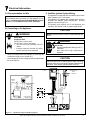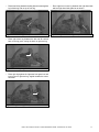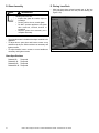
1
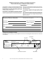
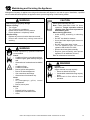
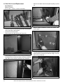
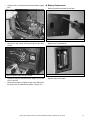
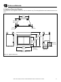
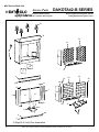
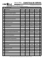
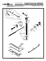
Owner’s Manual
Installation and Operation
Models:
Dakota 42-B
Dakota 42H-B
CAUTION
Important operating •
and maintenance
instructions included.
Read, understand •
and follow these
instructions for safe
installation and
operation.
T
O
N RD
O A
D SC
I
•
D
DO NOT DISCARD THIS MANUAL
L e a v e
t h i s
manual with party
responsible for use
and operation.
WARNING
WARNING
If the information in these instructions is not followed exactly, a
fire may result causing property
damage, personal injury, or death.
• Do not store or use gasoline or other flammable vapors and liquids in the vicinity of
this or any other appliance.
• What to do if you smell gas:
HOT! DO NOT TOUCH.
SEVERE BURNS MAY RESULT.
CLOTHING IGNITION MAY RESULT.
Glass and other surfaces are hot during
operation and cool down.
•
•
•
- Do not try to light any appliance.
- Do not touch any electrical switch. Do not
use any phone in your building.
- Immediately call your gas supplier from
a neighbor’s phone. Follow the gas
supplier’s instructions.
- If you cannot reach your gas supplier, call
the fire department.
• Installation and service must be performed
by a qualified installer, service agency, or
the gas supplier.
•
Keep children away.
CAREFULLY SUPERVISE children in same room as
appliance.
Alert children and adults to hazards of high
temperatures.
Keep clothing, furniture, draperies and other
combustibles away.
This appliance must be installed outside.
Note: An arrow (¨) found in the text signifies change in
content.
Installation and service of this appliance should
be performed by qualified personnel. Hearth &
Home Technologies suggests NFI certified or
factory-trained professionals, or
technicians supervised by an NFI
certified professional.
Heat & Glo LifeStyle Collection • Dakota 42-B/Dakota 42H-B • 4036-909 Rev D • 08/06
1
Read this manual before installing or operating this appliance.
Please retain this owner’s manual for future reference.
Congratulations
Congratulations on selecting a Heat & Glo LifeStyle Collection
gas appliance—an elegant and clean alternative to wood
burning appliances. The Heat & Glo LifeStyle Collection gas
appliance you have selected is designed to provide the utmost
in safety, reliability, and efficiency.
As the owner of a new appliance, you’ll want to read and
carefully follow all of the instructions contained in this owner’s
manual. Pay special attention to all cautions and warnings.
This owner’s manual should be retained for future reference.
We suggest you keep it with your other important documents
and product manuals.
The information contained in this owner’s manual, unless
noted otherwise, applies to all models and gas control
systems.
Your new Heat & Glo LifeStyle Collection gas appliance will
give you years of durable use and trouble-free enjoyment.
Welcome to the Heat & Glo LifeStyle Collection family of
appliance products!
We recommend that you record the following pertinent
information about your appliance:
Homeowner Reference Information
Model Name:
Date purchased/installed:
Serial Number:
Location on appliance:
Dealership purchased from:
Dealer phone:
Notes:
Listing Label Information/Location
The model information regarding your specific appliance can be found on the rating plate usually located in the control area
of the appliance.
Type of Gas
This appliance must be installed in accordance with local codes, if any; if not, follow ANSI Z223.1 in
the USA installation codes.
Heat & Glo Lifestyle Products
Hearth & Home Technologies Inc.
20802 Kensington Blvd., Lakeville, MN 55044
Vented gas fireplace - for outdoor installation
only. Not for use with solid fuel. (Foyer au
gaz à évacuation - pour installation à
l'extérieur seulement. Ne doit pas entre
utilise avec un combustible solide.)
ANSI Z21.50-2003 - CSA 2.22-M2003
Serial Number
Serial (Serie):
VENTED GAS
OD
FIREPLACE
Mfg. Date:
8R54
Minimum Permissible Gas Supply for Purposes
of Input Adjustment.
Natural Gas
Propane Gas
Approved Minimum (De Gaz) Acceptable . . 7.0 in. w.c. (Po. Col. d'eau) . . .11.0 in. w.c. (Po. Col. d'eau)
Maximum Pressure (Pression) . . . . . . . . . . 10.0 in. w.c. (Po. Col. d'eau) . .14.0 in. w.c. (Po. Col. d'eau)
Maximum Input BTUH: . . . . . . . . . . . . . . . . 60,000 . . . . . . . . . . . . . . . . . . .53,000
Orifice Size: . . . . . . . . . . . . . . . . . . . . . . . . #25DMS . . . . . . . . . . . . . . . . . .#44DMS
Model
(Modele):
MADE
IN USA
DAKOTA42-B
DAKOTA42L-B
This product is covered by one or more of the following patents: (Nos produits sont couverts par un ou plusieurs des brevels suivants): (United States) 4,112,913; 4,408,594; 4,422,426; 4,424,792; 4,520,791; 4,793,322; 4,852,548; 4,875,464; 5,000,162; 5,016,609; 5,076,254; 5,191,877;
5,218,953; 5,328,356; 5,429,495; 5,452,708; 5,542,407; 5,613,487; (Australia) 543790; 586383; (Canada) 1,123,296; 1,297,746; 2,195,264; (Mexico) 97-0457; (New Zealand) 200265; or other U.S. and foreign patents pending (ou autres brevets americains et etrangers en attente).
Gas and Electric Information
2
Heat & Glo LifeStyle Collection • Dakota 42-B/Dakota 42H-B • 4036-909 Rev D • 08/06
Model Number
4036-994A
Table of Contents
1 Listing and Code Approvals
A.
B.
C.
D.
Appliance Certification . . . . . . . . . . . . . . . . . . . . . . . . . 4
Glass Specifications . . . . . . . . . . . . . . . . . . . . . . . . . . 4
BTU Specifications . . . . . . . . . . . . . . . . . . . . . . . . . . . 4
High Altitude Installations . . . . . . . . . . . . . . . . . . . . . . 4
2 Getting Started
A. Design and Installation Considerations . . . . . . . . . . . . 5
B. Tools and Supplies Needed . . . . . . . . . . . . . . . . . . . . . 5
C. Inspect Appliance and Components . . . . . . . . . . . . . 5
3 Framing and Clearances
A. Select Appliance Location . . . . . . . . . . . . . . . . . . . . . . 6
B. Clearances . . . . . . . . . . . . . . . . . . . . . . . . . . . . . . . . . 7
C. Mantel Projections . . . . . . . . . . . . . . . . . . . . . . . . . . . . 7
4 Termination Locations
A. Vent Termination Minimum Clearances . . . . . . . . . . . . 8
5 Appliance Preparation
A. Remove Logs and Shipping Cover . . . . . . . . . . . . . . . 9
B. Securing and Leveling Appliance . . . . . . . . . . . . . . . . 9
6 Gas Information
A.
B.
C.
D.
E.
Fuel Conversion . . . . . . . . . . . . . . . . . . . . . . . . . . . . 10
Gas Pressure. . . . . . . . . . . . . . . . . . . . . . . . . . . . . . . 10
Gas Connection . . . . . . . . . . . . . . . . . . . . . . . . . . . . . 10
High Altitude Installations . . . . . . . . . . . . . . . . . . . . . 11
Valve Access . . . . . . . . . . . . . . . . . . . . . . . . . . . . . . . 12
9 Appliance Setup
A.
B.
C.
D.
E.
Clean the Appliance. . . . . . . . . . . . . . . . . . . . . . . . . . 16
Grate Assembly Placement . . . . . . . . . . . . . . . . . . . . 16
Positioning the Logs . . . . . . . . . . . . . . . . . . . . . . . . . 16
Glass Assembly . . . . . . . . . . . . . . . . . . . . . . . . . . . . . 18
Placing Lava Rock . . . . . . . . . . . . . . . . . . . . . . . . . . . 18
10 Operating Instructions
A.
B.
C.
D.
Before Lighting Appliance . . . . . . . . . . . . . . . . . . . . . 19
Lighting the Appliance . . . . . . . . . . . . . . . . . . . . . . . . 20
After the Appliance is Lit . . . . . . . . . . . . . . . . . . . . . . 21
Frequently Asked Questions . . . . . . . . . . . . . . . . . . . 21
11 Troubleshooting
A. Intellifire Ignition System . . . . . . . . . . . . . . . . . . . . . . 22
12 Maintaining and Servicing the Appliance
A. Valve Service and Replacement . . . . . . . . . . . . . . . . 24
B. Battery Replacement . . . . . . . . . . . . . . . . . . . . . . . . . 25
B. Maintenance and Service Tasks: . . . . . . . . . . . . . . . . 26
13 Reference Materials
A.
B.
C.
D.
Appliance Dimension Diagram . . . . . . . . . . . . . . . . . 27
Service Parts List. . . . . . . . . . . . . . . . . . . . . . . . . . . . 28
Warranty . . . . . . . . . . . . . . . . . . . . . . . . . . . . . . . . . . 35
Contact Information . . . . . . . . . . . . . . . . . . . . . . . . . . 36
7 Electrical Information
A. Recommendation for Wire . . . . . . . . . . . . . . . . . . . . . 13
B. Connecting to the Appliance . . . . . . . . . . . . . . . . . . . 13
C. Intellifire Ignition System Wiring . . . . . . . . . . . . . . . . 13
8 Finishing
A. Mantel Projections . . . . . . . . . . . . . . . . . . . . . . . . . . . 14
B. Facing Material . . . . . . . . . . . . . . . . . . . . . . . . . . . . . 15
Heat & Glo LifeStyle Collection • Dakota 42-B/Dakota 42H-B • 4036-909 Rev D • 08/06
3
1
Listing and Code Approvals
A. Appliance Certification
MODELS: Dakota 42-B, Dakota 42H-B
LABORATORY: Underwriters Laboratories, Inc. (UL)
TYPE: Vented Gas Appliance
STANDARD: ANSI Z21.50-2003—CSA2.22-M2003
This product is listed to ANSI standards for “Vented Gas
Fireplaces” and applicable sections of “Gas Burning Heating
Appliances for Manufactured Homes and Recreational Vehicles”, and “Gas Fired Appliances for Use at High Altitudes”.
B. Glass Specifications
Hearth & Home Technologies appliances manufactured with
tempered glass may be installed in hazardous locations such
as bathtub enclosures as defined by the Consumer Product
Safety Commission (CPSC). The tempered glass has been
tested and certified to the requirements of ANSI Z97.1 and
CPSC 16 CFR 1202 (Safety Glazing Certification Council
SGCC# 1595 and 1597. Architectural Testing, Inc. Reports
02-31919.01 and 02-31917.01).
This statement is in compliance with CPSC 16 CFR Section
1201.5 “Certification and labeling requirements” which refers
to 15 U.S. Code (USC) 2063 stating “…Such certificate shall
accompany the product or shall otherwise be furnished to
any distributor or retailer to whom the product is delivered.”
Some local building codes require the use of tempered glass
with permanent marking in such locations. Glass meeting
this requirement is available from the factory. Please contact
your dealer or distributor to order.
C. BTU Specifications
Maximum
Input BTUH
Orifice Size
(DMS)
Dakota 42-B (NG)
60,000
25
Dakota 42-B (LP)
53,000
44
Models
D. High Altitude Installations
U.L. Listed gas appliances are tested and approved without
requiring changes for elevations from 0 to 2000 feet in the
U.S.A. and Canada.
When installing this appliance at an elevation above 2000 ft,
it may be necessary to decrease the input rating by changing the existing burner orifice to a smaller size. Input rate
should be reduced by 4% for each 1000 ft above a 2000 ft
elevation in the U.S.A., or 10% for elevations between 2000
and 4500 ft in Canada. If the heating value of the gas has
been reduced, these rules do not apply. To identify the proper orifice size, check with the local gas utility.
If installing this appliance at an elevation above 4500 ft (in
Canada), check with local authorities.
WARNING
Do NOT use this appliance if any part has been under
water. Immediately call a qualified service technician
to inspect the appliance and to replace any part of the
control system and any gas control which has been
under water.
Note: This installation must conform with local codes. In the
absence of local codes you must comply with the National
Fuel Gas Code, ANSI Z223.1-latest edition in the U.S.A.
and the CAN/CGA B149 Installation Codes in Canada.
4
Heat & Glo LifeStyle Collection • Dakota 42-B/Dakota 42H-B • 4036-909 Rev D • 08/06
2
Getting Started
A. Design and Installation Considerations
Note: This appliance must be installed outside.
B. Tools and Supplies Needed
Before beginning the installation be sure that the following
tools and building supplies are available.
Reciprocating saw
Framing material
Pliers
Hi temp caulking material
Hammer
Gloves
Phillips screwdriver
Framing square
Flat blade screwdriver Electric drill and bits (1/4 in.)
Plumb line
Safety glasses
Manometer
Voltmeter
Tape measure
Level
Non-corrosive leak check solution
1/2 - 3/4 inch length, #6 or #8 Self-drilling screws
CAUTION
Check building codes prior to installation.
• Installation MUST comply with local, regional,
state and national codes and regulations.
• Consult insurance carrier, local building, fire
officials or authorities having jurisdiction about
restrictions, installation inspection, and permits.
When planning an appliance installation, it’s necessary to
determine the following information before installing:
•
•
•
•
C. Inspect Appliance and Components
Where the appliance is to be installed.
Gas supply piping.
Electrical wiring.
Framing and finishing details.
WARNING
Inspect appliance and components for
damage. Damaged parts may impair safe
operation.
•
•
•
¨ Moisture Resistance:
This outdoor fireplace will shed moderate amounts of water,
but is not waterproof. Water and condensing water vapor
may enter the chase under certain conditions.
The fireplace will not perform as an exterior wall. Moisture
penetration must be considered for construction that places
the fireplace in structure walls or on moisture sensitive surfaces.
When installed on exterior walls: Hearth & Home Technologies recommends that the fireplace chase be constructed outside the structure’s weather envelope. Where
the platform meets the wall, use a flashing detail similar to
that required for attached decks. Chase platforms, including
hearths should slope away from the structure at 1/8 in. to
1/4 in. per foot. The fireplace can be shimmed level.
When installed on surfaces where water may collect or
cause damage: Hearth & Home Technologies recommends
that a drainage pan be placed under the unit. This can be
constructed of metal, adhesive polymer membrane (such as
ice and water shield) or other suitable materials. A means of
drainage out of the pan such as tubes or weep holes should
be provided. A slope of 1/8 in. to 1/4 in. per foot towards
the drain port is suggested. The fireplace can be shimmed
level.
Hearths should slope away from the front of the fireplace
and chase at 1/8 in. to 1/4 in. per foot. Spark strips must be
on top of any combustible hearth materials used for moisture
management.
Do NOT install damaged components.
Do NOT install incomplete components.
Do NOT install substitute components.
Report damaged parts to dealer.
•
Carefully remove the appliance and components from the
packaging.
The gas logs may be packaged separately and must be
field installed.
Report to your dealer any parts damaged in shipment,
particularly the condition of the glass.
Read all of the instructions before starting the
installation. Follow these instructions carefully
during the installation to ensure maximum safety and
benefit.
•
•
•
WARNING
Hearth & Home Technologies disclaims any
responsibility for, and the warranty will be
voided by, the following actions:
•
•
•
•
•
Installation and use of any damaged appliance or
vent system component.
Modification of the appliance or vent system.
Installation other than as instructed by Hearth & Home
Technologies.
Improper positioning of the gas logs or the glass
door.
Installation and/or use of any component part not
approved by Hearth & Home Technologies.
Any such action may cause a fire hazard.
Heat & Glo LifeStyle Collection • Dakota 42-B/Dakota 42H-B • 4036-909 Rev D • 08/06
5
3
Framing and Clearances
Note:
•
•
•
WARNING
Illustrations reflect typical installations and are FOR
DESIGN PURPOSES ONLY.
Illustrations/diagrams are not drawn to scale.
Actual installation may vary due to individual design
preference.
Fire Risk
Provide adequate clearance:
• Around air openings.
• To combustibles.
• For service access.
Locate appliance away from traffic areas.
A. Select Appliance Location
When selecting a location for your appliance it is important to
consider the required clearances to walls (See Figure 3.1).
Note: If this surface is
inside the building’s
warm air envelope...
Note: For actual appliance
dimensions refer to Section 13.
...then this surface
must be an exterior
wall system.
G
57-3/4 in.
(1467 mm)
B
A
G
F
F
F
C
E
D
C
D
E
Figure 3.1
81-3/4 in.
(2076 mm)
A
B
C
D
E
F
G
in.
24-3/4
24-1/8
48
49
5/8
1/2
1-1/2
mm
629
613
1219
1245
16
13
38
Appliance Locations
WARNING
Fire Risk
Odor Risk
•
•
6
Install appliance on hard metal or wood
surfaces extending full width and depth
of appliance.
Do NOT install appliance directly on
carpeting, vinyl, tile or any combustible
material other than wood.
WARNING
Fire Risk
• Locate and install appliance to all
clearance specifications in manual.
Heat & Glo LifeStyle Collection • Dakota 42-B/Dakota 42H-B • 4036-909 Rev D • 08/06
B. Clearances
Framing Dimensions
B
C
D
in.
24-1/8
mm
613
43-7/8
49
43-7/8
1114
1245
1114
D
Header height.
Use only noncombustible
material below the top of
the top standoffs.
B
C
A
Upper front can be
covered with
non-combustible
material or removed
and replaced with
non-combustible
material.
A
0 in. to level
of standoffs
1-1/2 in. (38 mm)
84 in.
(2134 mm)
to ceiling
1-1/2 in.
(38 mm)
1/2 in. (13 mm)
Combustible Object
Drywall
Figure 3.2
0 in.
36 in.
(914 mm)
0 in.
Combustible flooring may be installed next
to the front of the appliance.
Framing Dimensions
C. Mantel Projections
Roof or
Overhang
Fi
re
pl
ac
e
12 in. (305 mm)
max. combustible
mantel depth
re
ctu
tru l
S
l
al
na ew
itio Sid
d
Ad or
84 in.
(2134 mm)
minimum
height
St
Ma
ru
nte
ct
ur
l
e
B
in.
mm
in.
mm
Figure 3.3
Then B
must be at
least:
If A is:
6 - 36
26
152 - 914
660
36 or more
18
914 or more
457
A
Clearances to Mantels or Other Combustibles Above Appliance
Heat & Glo LifeStyle Collection • Dakota 42-B/Dakota 42H-B • 4036-909 Rev D • 08/06
7
4
Termination Locations
A. Vent Termination Minimum Clearances
O
P
G
N
R
FP
A
D
FP
H
Q
E
(See Note 2)
B
L
FP
F
B
FP
B
FP
FP
I
M
FP
A
FP = FIREPLACE OPENING
A
=
B
=
D** =
F
G*
=
=
H
=
I
=
*
**
***
J or K
X = AIR SUPPLY INLET
0 in. . . . . . . . . . clearances above grade,
veranda, porch, deck or
balcony.
12 in. . . . . . . . . . clearances to window or door
that may be opened, or to
permanently closed window.
36 in. . . . . . . . . . vinyl windows or siding.
47 in. . . . . . . . . . vertical clearance to unventilated soffit or to ventilated soffit
located above the terminal.
60 in. . . . . . . . . . vinyl clad soffits.
9 in. . . . . . . . . . clearance to outside corner.
6 in. . . . . . . . . . clearance to inside corner.
48 in. . . . . . . . . . vinyl windows or siding.
3 ft. (Canada) . not to be installed above a gas
meter/regulator assembly within
3 ft (914 mm) horizontally from
the center line of the regulator.
3 ft. (USA)
6 ft. (Canada) . clearance to service regulator
vent outlet and electric service.
48 in. minimum for vinyl windows or vinyl siding.
Not allowed for vinyl clad soffits.
a fireplace shall not open directly above a sidewalk or paved
driveway which is located between two single family dwellings
and services both dwellings.
**** only permitted if veranda, porch, deck or balcony is fully open
on a minimum of 2 sides beneath the floor, or if the screened
porch guidelines are followed.
Note 1: Local codes or regulations may require different clearances.
Note 2: Termination in an alcove space (spaces open only on one
side and with an overhang) are permitted with the dimensions
specified for vinyl or non-vinyl siding and soffits. 1) There must
be a 3 ft minimum between terminations or between the
fireplace and termination. 2) All mechanical air intakes within 10
ft of a termination must be a minimum of 3 ft below the fireplace
hood. 3) All gravity air intakes within 3 ft of the fireplace hood
must be a minimum of 1 ft below the termination.
= AREA WHERE FIREPLACE IS NOT PERMITTED
J
=
9 in. (USA)
12 in. (Canada) . clearance to non-mechanical air
supply inlet to building or the
combustion air inlet to any other
appliance.
K
=
3 ft. (USA)
6 ft. (Canada) . clearance to a mechanical air
supply inlet.
L*** = 54 in. . . . . . . . . . clearance above paved sidewalk
(See note 1)
or a paved driveway located on
public property.
M****= 47 in. . . . . . . . . . clearance under veranda, porch,
deck, balcony or overhang.
Not allowed: . . . . . . vinyl
N
= 6 in. . . . . . . . . . non-vinyl siding.
P
= 84 in.
QMIN
RMAX
Dakota
10 feet
2 x Q ACTUAL
___________________________________________________________________________
1 additional termination cap
Q + 3 feet
1xQ
ACTUAL
___________________________________________________________________________
2 additional termination caps Q + 6 feet 2/3 x Q ACTUAL
___________________________________________________________________________
3 additional termination caps
Q + 9 feet
1/2 x Q ACTUAL
RMAX = (2 / # caps plus fireplace ) x Q ACTUAL
This fireplace is approved for installation onto screen porches with the
following guidelines:
Minimum porch area: 96 sq ft
Minimum ceiling height: 92 in.
Minimum of two walls must be screened
Minimum top of screen height, side walls: 6 ft 8 in.
Minimum screen area: 64 sq ft
Note 2: There may be some odor and small amounts of soot associated
with burning the Dakota on a screened porch. Ensuring good cross
draft ventilation and routine maintenance of the fireplace will maximize
comfort and cleanliness.
Figure 4.1 Minimum Clearances
8
X
Heat & Glo LifeStyle Collection • Dakota 42-B/Dakota 42H-B • 4036-909 Rev D • 08/06
5
Appliance Preparation
CAUTION
B. Securing and Leveling Appliance
WARNING
Sharp Edges
• Wear protective gloves
and safety glasses during
installation.
Fire Risk
•
•
A. Remove Logs and Shipping Cover
Open the doors by sliding the handles toward the outside
edges of the doors (see Figure 5.1) Remove the cartons of
logs from their shipping location in the appliance.
Open
Open
The diagram shows how to properly position, level, and secure the appliance (see Figure 5.2). Nailing tabs are provided to secure the appliance to the framing members.
•
•
•
•
•
•
Figure 5.1
Prevent contact with sagging, loose
insulation.
Do NOT install against vapor barriers or
exposed insulation.
Place the appliance into position on either a combustible
or non-combustible continuous flat surface.
Note: Remove the top standoffs before sliding appliance
into position if using an FPS prefab enclosure.
Level the appliance from side to side and front to back.
Shim the appliance with non-combustible material, such
as sheet metal, as necessary.
Bend out nailing tabs on each side.
Keep nailing tabs flush with the framing.
Secure the appliance to the framing by using nails or
screws through the nailing tabs.
Upper front can be
covered with
non-combustible
material or removed
and replaced with
non-combustible
material.
Door Operation
NAILING TABS
Figure 5.2
Proper Positioning, Leveling and Securing of an
Appliance
CAUTION
Do NOT notch into the framing around the appliance
spacers.
Heat & Glo LifeStyle Collection • Dakota 42-B/Dakota 42H-B • 4036-909 Rev D • 08/06
9
6
Gas Information
A. Fuel Conversion
C. Gas Connection
Before making gas connections ensure appliance being installed is compatible with the available gas type.
Note: Have the gas supply line installed in accordance
with local building codes, if any. If not, follow ANSI
223.1. Installation should be done by a qualified installer
approved and/or licensed as required by the locality. (In
the Commonwealth of Massachusetts installation must be
performed by a licensed plumber or gas fitter.)
Any natural or propane gas conversions necessary to meet
the appliance and locality needs must be made by a qualified technician using Hearth & Home Technologies specified
and approved parts.
B. Gas Pressure
Proper input pressures are required for optimum appliance
performance. Gas line sizing requirements need to be made
following NFPA51.
Note: A listed (and Commonwealth of Massachusetts
approved) 1/2 in. (13 mm) T-handle manual shut-off valve
and flexible gas connector are connected to the 1/2 in.
(13 mm) control valve inlet.
•
WARNING
Fire Risk
Explosion Risk
High pressure will damage valve.
• Disconnect gas supply piping BEFORE
pressure testing gas line at test pressures
above 1/2 psig.
• Close the manual shutoff valve BEFORE
pressure testing gas line at test pressures
equal to or less than 1/2 psig.
If substituting for these components, please consult
local codes for compliance.
Optional: A 5 ft flexible gas line is available to those regions
which do not require black pipe to be used. See Service
Parts List (Section 13).
Note: Gas line MUST be run from right side of appliance.
WARNING
WARNING
Gas Leak Risk
• Support control when attaching pipe to
prevent bending gas line.
Fire Risk
Explosion Risk
Verify inlet pressures.
• High pressure may cause overfire
condition.
• Low pressure may cause explosion.
Install regulator upstream of valve if line
pressure is greater than 1/2 psig.
Pressure requirements for appliance are shown in table
below.
Pressure
Natural Gas
Propane
Minimum Inlet Pressure
5.0 inches w.c.
11.0 inches w.c.
Maximum Inlet Pressure
7.0 inches w.c.
14.0 inches w.c.
Manifold Pressure
3.5 inches w.c.
10.5 inches w.c.
Note: The gap between supply piping and gas access hole
may be plugged with non-combustible unfaced insulation
to prevent cold air infiltration.
•
•
Ensure that gas line does not come in contact with outer
wrap of appliance. Follow local codes.
Incoming gas line should be piped into the valve
compartment and connected to the 1/2 in. connection on
the manual shutoff valve.
These pressures can be verified through the internal valve
access panels as shown in Section E. Valve Access.
10
Heat & Glo LifeStyle Collection • Dakota 42-B/Dakota 42H-B • 4036-909 Rev D • 08/06
WARNING
Fire Risk
Explosion Risk
• Gas build-up during line purge may
ignite.
• Purge should be performed by qualified
technician.
• Ensure adequate ventilation.
• Ensure there are no ignition sources such
as sparks or open flames.
•
A small amount of air will be in the gas supply lines. When
first lighting appliance it will take a short time for air to
purge from lines. When purging is complete, the appliance
will light and operate normally.
D. High Altitude Installations
U.L. listed gas appliances are tested and approved without
requiring changes for elevations from 0 to 2000 ft in the USA
and Canada.
When installing this appliance at an elevation above 2000 ft,
it may be necessary to decrease the input rating by changing the existing burner orifice to a smaller size. Input rate
should be reduced by 4% for each 1000 ft above a 2000 ft
elevation in the U.S.A., or 10% for elevations between 2000
and 4500 ft in Canada. If the heating value of the gas has
been reduced, these rules do not apply. To identify the proper orifice size, check with the local gas utility.
If installing this appliance at an elevation above 4500 ft (in
Canada), check with local authorities.
WARNING
CHECK FOR GAS LEAKS
Fire Risk
Explosion Risk
Asphyxiation Risk
• Check all fittings and connections.
• Do not use open flame.
• After the gas line installation is complete,
all connections must be tightened and
checked for leaks with a commercially
available, non-corrosive leak check
solution. Be sure to rinse off all leak check
solution following testing.
Fittings and connections may have loosened
during shipping and handling.
WARNING
Fire Risk
Explosion Risk
Do NOT change the valve settings.
• This valve has been preset at the
factory.
• Changing valve settings may result in fire
hazard or bodily injury.
Heat & Glo LifeStyle Collection • Dakota 42-B/Dakota 42H-B • 4036-909 Rev D • 08/06
11
E. Valve Access
•
•
The gas valve can be accessed behind the cement
refractory panel on the right side of the fireplace.
Lift doors out and set aside. There is a washer under each
door. Be careful not to loose those washers.
•
Remove the inside valve access panel by lifting it up and
out.
Washer
Figure 6.4
•
Figure 6.1
•
Lift Out Doors
Remove Valve Access Panel
Use a phillips screwdriver to remove the exterior valve
access panel (remove four screws).
Remove logs if access is necessary after installation is
complete. See Section 9.C. Remove logs in reverse order
of set up.
Remove grate if access is necessary after installation is
complete. (Refer to Section 9.B.)
Remove two screws on side of pilot shield and remove
shield.
•
•
Figure 6.5
•
Figure 6.2
•
Remove Pilot Shield
Use a phillips screwdriver to remove the two screws
securing the refractory retaining strip. Remove the
refractory side panel and set aside.
Use a manometer on the lower out pressure tap. Start
up the fireplace to verify the pressure and adjust as
necessary. Reverse these steps to reassemble before log
positioning.
Figure 6.6
Figure 6.3
12
Remove Exterior Valve Access Panel
Connect Manometer
Loosen Refractory Retaining Strip
Heat & Glo LifeStyle Collection • Dakota 42-B/Dakota 42H-B • 4036-909 Rev D • 08/06
7
Electrical Information
A. Recommendation for Wire
C. Intellifire Ignition System Wiring
Note: This appliance must be electrically wired and grounded
in accordance with local codes or, in the absence of local
codes, with National Electric Code ANSI/NFPA 70-latest
edition or the Canadian Electric Code, CSA C22.1.
•
•
•
This appliance is equipped with an Intellifire control valve
which operates on a 3 volt system.
This appliance is supplied with a battery pack which is
located in the ON/OFF switch terminal box. A wiring
diagram is shown in Figure 7.1.
The battery pack requires two D cell batteries (not
included). See Section 12.B. for battery replacement.
B. Connecting to the Appliance
CAUTION
WARNING
Shock Risk
Explosion Risk
Do NOT wire 110V to valve.
Do NOT wire 110V to wall switch
• Incorrect wiring will damage millivolt
values.
• Incorrect wiring will override IPI safety
lockout and may cause explosion.
Shock Risk
• Replace damaged wire with type 105° C
rated wire.
• Wire must have high temperature
insulation.
CAUTION
Label all wires prior to disconnection when servicing
controls. Wiring errors can cause improper and dangerous
operation. Verify proper operation after servicing.
I
IGNITION MODULE
3 VAC
INTERMITTENT
PILOT
IGNITOR
S
BATTERY
PACK
ON/OFF
WALL
SWITCH
FLAME SPARKER/
SENSOR
IGNITION
MODULE
(3V)
WHT
BATTERY
PACK
ORG
BLACK
GROUND TO
FIREPLACE
CHASSIS
LOW VOLTAGE
SEE NOTE 1
GRN
VALVE
ORG
RED
BRN
•
Keep wire lengths short as possible by removing any
excess wire length, not to exceed 18 ft.
Low voltage and 110 VAC voltage cannot be shared within
the same wall box.
WARNING
BRN
•
Battery polarity must be correct or module damage will
occur.
PIGGYBACK
ON/OFF SWITCH
VALVE
Figure 7.1
Intellefire Pilot Ignition (IPI) Wiring Diagram
Heat & Glo LifeStyle Collection • Dakota 42-B/Dakota 42H-B • 4036-909 Rev D • 08/06
13
8
Finishing
A. Mantel Projections
Figure 8.1 shows the minimum vertical dimension of appliance mantels or other combustible projections above the top front
edge of the appliance.
Roof or
Overhang
12 in. (305 mm)
max. combustible
mantel depth
re
ctu
u
r
St ll
al wa
n
io de
dit Si
Ad or
Fi
re
pl
ac
84 in.
(2134 mm)
minimum
height
e
St
Ma
ru
nte
ct
ur
l
e
B
in.
mm
in.
mm
Figure 8.1
14
Then B
must be at
least:
If A is:
6 - 36
26
152 - 914
660
36 or more
18
914 or more
457
A
Clearances to Mantels or other Combustibles above Appliance.
Heat & Glo LifeStyle Collection • Dakota 42-B/Dakota 42H-B • 4036-909 Rev D • 08/06
B. Facing Material
WARNING
Fire Risk
Do NOT obstruct air inlet or outlet grilles.
Do NOT modify grilles.
• Modifying or covering grilles could cause
temperature rise and fire hazard.
Finishing materials must not interfere with:
• Air flow through grilles or louvers.
• Operation of louvers or doors.
• Access for service.
Finish wall material
may be combustible,
top & sides.
Upper front can be covered
with non-combustible
material or removed and
replaced with noncombustible material.
0 in.
0 in.
Figure 8.2
Sealant Material
0 in.
Noncombustible Facing Diagram
WARNING
Fire Risk
Finish all edges and fronts to clearances and
specifications listed in manual.
•
•
•
•
Metal appliance front may be covered with noncombustible material only.
Do NOT overlap combustible materials onto appliance
front.
Install combustible materials up to specified clearances
on top front and side edges.
Seal joints between the finished wall and appliance
top and sides using only a 300° F minimum sealant.
Heat & Glo LifeStyle Collection • Dakota 42-B/Dakota 42H-B • 4036-909 Rev D • 08/06
15
9
Appliance Setup
A. Clean the Appliance
C. Positioning the Logs
Clean/vacuum any sawdust that may have accumulated inside the firebox or underneath in the control cavity.
•
•
See Section 13.B. for log descriptions and illustrations.
Place right rear log on the grate against the appliance right
side wall.
WARNING
Shock Risk
Fire Risk
Use ONLY optional accessories approved
for this appliance.
• Using non-listed accessories voids
warranty.
• Using non-listed accessories may result
in a safety hazard.
• Only Hearth & Home Technologies
approved accessories may be used
safely.
Figure 9.2
•
Right Rear Log (SRV720)
Place the left rear log on the grate against the left wall and
rest it on log.
B. Grate Assembly Placement
•
Ensure grate assembly is over burner assembly, centered
from left to right, and back legs are in grate brackets (see
Figure 9.1)
Figure 9.3
•
Back Legs in Grate Brackets
Figure 9.1
Place the fork of log onto the left front bar and rest its back
on right rear log.
Back Legs in Grate Brackets
Figure 9.4
•
Left Side Log (SRV723)
Place front log in front of the main grate with its left end
resting on left rear log as shown.
Figure 9.5
16
Left Rear Log (SRV728)
Front Log (SRV727)
Heat & Glo LifeStyle Collection • Dakota 42-B/Dakota 42H-B • 4036-909 Rev D • 08/06
•
Place front left log between locating bars so it rests against
log left side log and on top of front log.
Figure 9.6
•
Place right front corner log between the right hand side
wall and right hand side grate bar as shown.
Figure 9.9
Right Front Corner Log (SRV742)
Place right center log between the 4th and 5th vertical
bars on the log grate, resting the back on right rear log.
Figure 9.7
•
Front Left Log (SRV722)
•
Front Right Log (SRV724)
Place right log against the rightmost front grate bar and
rest its rear on right rear log, angled towards the corner
as shown.
Figure 9.8
Right Side Log (SRV740)
Heat & Glo LifeStyle Collection • Dakota 42-B/Dakota 42H-B • 4036-909 Rev D • 08/06
17
D. Glass Assembly
E. Placing Lava Rock
•
WARNING
Handle glass with care.
• Inspect the glass for cracks, chips or
scratches.
• Do NOT strike, slam or scratch glass.
• Do NOT operate appliance with glass
door removed, cracked, broken or
scratched.
• Replace glass door assembly as a
complete assembly.
•
•
•
The glass doors are included with and pre-installed in the
appliance.
To adjust doors, open them and loosen screws on top
and bottom pivot pins. Slide each door as necessary and
tighten screws.
To adjust handle, loosen screws to move handles as
necessary and tighten screws.
After logs have been placed spread part of the lava
rock (included) between the rock pan and ashlip (see
Figure 9.10).
Rock Pan
Ashlip
Figure 9.10 Placement of Lava Rocks
Glass Specifications
Dakota42-B:
Dakota42L-B:
Dakota42H-B:
Dakota42HL-B:
18
Tempered
Tempered
Tempered
Tempered
Heat & Glo LifeStyle Collection • Dakota 42-B/Dakota 42H-B • 4036-909 Rev D • 08/06
10
Operating Instructions
A. Before Lighting Appliance
Before operating this appliance, have a qualified
technician:
•
Remove all shipping materials from inside and/or
underneath the firebox.
Review proper placement of logs, rockwool, lava rock and
vermiculite.
Check the wiring.
Check the air shutter adjustment.
Ensure that there are no gas leaks.
Ensure that the flow of combustion and ventilation air is
not obstructed (front grilles).
•
•
•
•
•
WARNING
•
•
•
•
•
WARNING
Improper installation, adjustment, alteration, service or
maintenance can cause injury or property damage. Refer
to the owner’s information manual provided with this
appliance. For assistance or additional information consult
a qualified installer, service agency or the gas supplier.
WARNING
Do NOT use this appliance if any part has been under
water. Immediately call a qualified service technician
to inspect the appliance and to replace any part of the
control system and any gas control which has been
under water.
Fire Risk
Burn Risk
HOT! DO NOT TOUCH.
SEVERE BURNS MAY RESULT.
CLOTHING IGNITION MAY RESULT
Glass and other surfaces are hot during
operation and cool down.
Keep children away.
CAREFULLY SUPERVISE children in same room as
appliance.
Alert children and adults to hazards of high
temperatures.
Do NOT operate with protective barriers open or
removed.
Keep clothing, furniture, draperies and other
combustibles away.
Heat & Glo LifeStyle Collection • Dakota 42-B/Dakota 42H-B • 4036-909 Rev D • 08/06
19
B. Lighting the Appliance
Intellifire Ignition
FOR YOUR SAFETY
READ BEFORE LIGHTING
WARNING: If you do not follow these instructions
exactly, a fire or explosion may result causing property
damage, personal injury or loss of life.
A. This appliance is equipped with • Do not touch any electric switch; do
an intermittent pilot ignition (IPI)
not use any phone in your building.
device which automatically lights • Immediately call your gas supplier
the burner. Do not try to light the
from a neighbor’s phone. Follow
burner by hand.
the gas supplier’s instructions.
B. BEFORE LIGHTING, smell all • If you cannot reach your gas suparound the appliance area for
plier, call the fire department.
gas. Be sure to smell next to
C. Do not use this appliance if any part
the floor because some gas is
has been under water. Immediately
heavier than air and will settle on
call a qualified service technician
the floor.
to inspect the appliance and to
replace any part of the control
WHAT TO DO IF YOU SMELL
system and any gas control which
GAS
has been under water.
• Do not try to light any appliance.
LIGHTING
INSTRUCTIONS
1. Turn off wall switch.
2. This appliance is equipped with an ignition device which automatically lights the
burner. Do not try to light the burner by
hand.
GAS
VALVE
3. Wait five (5) minutes to clear out any gas.
Then smell for gas, including near the
floor. If you smell gas, STOP! Follow “B”
in the Safety Information located on the left
side of this label. If you don’t smell gas,
go to next step.
WARNING:
CAUTION:
DO NOT CONNECT 110 VAC
TO THE CONTROL VALVE.
Hot while in operation. Do not touch.
Keep children, clothing, furniture,
gasoline and other liquids having
flammable vapors away.
5. To light the burner, flip the ON/OFF
switch to the “ON” position. (The ON/OFF
switch may include a wall switch if so
equipped).
Do not operate the appliance with
panel(s) removed, cracked or broken. Replacement of the panel(s)
should be done by a licensed or
qualified service person.
6. If the appliance will not operate, check
battery then follow the instructions “To
Turn Off Gas to Appliance” and call your
service technician or gas supplier.
NOT FOR USE
WITH SOLID FUEL
TO TURN OFF
GAS TO APPLIANCE
Improper installation, adjustment,
alteration, service or maintenance
can cause injury or property damage. Refer to the owner’s information manual provided with this
appliance.
This appliance needs fresh air for
safe operation and must be installed
so there are provisions for adequate
combustion and ventilation air.
If not installed, operated, and maintained in accordance with the manufacturer’s instructions, this product
could expose you to substances in
fuel or fuel combustion which are
known to the State of California to
cause cancer, birth defects, or other
reproductive harm.
4. Turn on wall switch.
For use with natural gas and propane. A conversion kit, as supplied
by the manufacturer, shall be used
to convert this appliance to the alternate fuel.
1. Turn off all electric power to the appliance
if service is to be performed.
2. Flip ON/OFF switch to the “OFF” position.
Keep burner and control compartment clean. See installation and
operating instructions accompanying
appliance.
Final Inspection by _________________________________
20
Heat & Glo LifeStyle Collection • Dakota 42-B/Dakota 42H-B • 4036-909 Rev D • 08/06
C. After the Appliance is Lit
CAUTION
Initial Break-in Procedure
When you light the appliance, you may notice that it produces heat which does have an associated odor or smell. If
you feel this odor is excessive it may require the initial three
to four hour continuous burn on high followed by a second
burn up to 12 hours to fully drive off any odor from paint and
lubricants used in the manufacturing process. Condensation
of the glass is normal
Note: This appliance should be run three to four hours
on the initial start-up. Turn it off and let it cool completely.
Remove and clean the glass. Replace the glass and run
the appliance for an additional 12 hours. This will help cure
the products used in the paint and logs.
•
•
•
Prevent accidental appliance operation when not
attended.
Unplug or remove batteries from remote switch if
absent or if appliance will not be used for an extended
period of time.
Property damage possible from elevated
temperatures.
CAUTION
Smoke and odors are released during initial
operation.
Smoke and odors may be irritating to sensitive
individuals.
WARNING
Fire Risk
High Temperatures
Keep combustible household items away
from appliance.
Do NOT obstruct combustion and ventilation
air.
• Do NOT place combustible items on top
of or in front of appliance.
• Keep furniture, draperies away from
appliance.
WARNING
Fire Risk
Keep combustible materials, gasoline and
other flammable vapors and liquids clear of
appliance.
• Do NOT store flammable materials in the
vicinity of the appliance.
• Do NOT use gasoline, lantern fuel,
kerosene, charcoal lighter fluid or similar
liquids in this appliance.
Combustible materials may ignite.
D. Frequently Asked Questions
Issue
Solutions
Condensation on the glass
This is a result of gas combustion and temperature variations. As the appliance warms, this condensation will
disappear.
Blue flames
This is a result of normal operation and the flames will begin to yellow as the appliance is allowed to burn for 20 to
40 minutes.
Odor from appliance
When first operated, this appliance may release an odor for the first several hours. This is caused by the curing of
the paint and the burning off of any oils remaining from manufacturing.
Film on the glass
This is a normal result of the curing process of the paint and logs. Glass should be cleaned within 3 to 4 hours of
initial burning to remove deposits left by oils from the manufacturing process. A non-abrasive cleaner such as gas
fireplace glass cleaner may be necessary. See your dealer.
Metallic noise
Noise is caused by metal expanding and contracting as it heats up and cools down, similar to the sound produced
by a furnace or heating duct. This noise does not affect the operation or longevity of the fireplace.
Is it normal to see the pilot
flame burn continually?
In an Intellifire ignition system it is normal to see the pilot flame, but it should turn off when ON/OFF is turned off.
In a standing pilot system the pilot will always stay on.
Heat & Glo LifeStyle Collection • Dakota 42-B/Dakota 42H-B • 4036-909 Rev D • 08/06
21
11
Troubleshooting
With proper installation, operation and maintenance your gas appliance will provide years of trouble-free service. If you do
experience a problem, this troubleshooting guide will assist a qualified service person in the diagnosis of a problem and the
corrective action to be taken. This troubleshooting guide can only be used by a qualified service technician.
A. Intellifire Ignition System
Symptom
1.
2.
3.
4.
22
Possible Causes
The ignitor/module makes
noise, but no spark.
Pilots won’t light, there is
no noise or spark.
Pilot lights but continues
to spark, and main burner
will not ignite. (If the pilot
continues to spark after
the pilot flame has been
lit, flame rectification has
not occurred.)
Pilot sparks, but pilot will
not light.
Corrective Actions
A.
Incorrect wiring.
Verify “S” wire (white) for sensor and “I” wire (orange) for ignitor are connected to the
correct terminals on the module and the pilot assembly. Reversed wires at the module
may cause the system to make a sparking noise, but the spark may not be present at
pilot hood.
B.
Loose connections or
electrical shorts in the
wiring.
Verify there are no loose connections or electrical shorts in wiring from module to
pilot assembly. The rod closest to the pilot hood should be ignitor. Verify connections
underneath pilot assembly are tight; also verify the connections are not grounding out
to the metal chassis, pilot burner, pilot enclosure, mesh screen if present, or any other
metal object.
C.
Ignitor gap is too large.
Verify gap of ignitor to pilot hood. The gap should be approximately .17 in. or 1/8 in.
D.
Faulty module.
Turn ON/OFF rocker switch or wall switch to OFF position. Remove ignitor wire “I”
from module. Place ON/OFF rocker switch or wall switch in ON position. Hold ground
wire about 3/16 in. away from “I” terminal on module. If there is no spark at “I” terminal,
module must be replaced. If there is a spark at “I” terminal, module is fine. Inspect pilot
assembly for shorted sparker wire or cracked insulator around electrode.
A.
Transformer installed
incorrectly.
Verify that transformer is installed and plugged into module. Check voltage of
transformer under load at space connection on module with ON/OFF switch in ON
position. Acceptable readings of a good transformer are between 3.2 and 2.8 volts AC.
B.
A shorted or loose
connection in wiring
configuration or wiring
harness.
Remove and reinstall the wiring harness that plugs into module. Verify there is a tight
fit. Verify pilot assembly wiring to module. Remove and verify continuity of each wire in
wiring harness.
C.
Improper wall switch
wiring.
Verify wall switch is wired correctly.
D.
Module not grounded.
Verify black ground wire from module wire harness is grounded to metal chassis of
appliance.
E.
Faulty module.
Turn ON/OFF rocker switch or wall switch to OFF position. Remove ignitor wire “I”
from module. Place ON/OFF rocker switch or wall switch in ON position. Hold ground
wire about 3/16 in. away from “I” terminal on module. If there is no spark at “I” terminal
module must be replaced. If there is a spark at “I” terminal, module is fine. Inspect pilot
assembly for shorted sparker wire or cracked insulator around electrode.
A.
A shorted or loose
connection in sensor rod.
Verify all connections to wiring diagram in manual. Verify connections underneath pilot
assembly are tight. Verify connections are not grounding out to metal chassis, pilot
burner, pilot enclosure or screen if present, or any other metal object.
B.
Poor flame rectification or
contaminated sensor rod.
Verify flame is engulfing sensor rod. If the pilot assembly does not have a ground
strap, consider installing one to increase flame rectification. Verify correct pilot orifice
is installed and inlet gas specifications are met. Flame carries rectification current, not
the gas. If flame lifts from pilot hood, the circuit is broken. A wrong orifice or too high
an inlet pressure can cause pilot flame to lift. The sensor rod may be contaminated.
Clean sensor rod with emery cloth.
C.
Module is not grounded.
Verify that module is securely grounded to metal chassis of appliance. Verify that the
wire harness is firmly connected to module.
D.
Damaged pilot assembly
or dirty sensor rod.
Verify that ceramic insulator around the sensor rod is not cracked, damaged, or loose.
Verify connection from sensor rod to white sensor wire. Clean sensor rod with emery
cloth to remove any contaminants that may have accumulated on sensor rod. Verify
continuity with a multimeter with ohms set at lowest range.
E.
Faulty module.
Turn ON/OFF rocker switch or wall switch to OFF position. Remove ignitor wire “I”
from module. Place ON/OFF rocker switch or wall switch in ON position. Hold ground
wire about 3/16 in. away from “I” terminal on module. If there is no spark at “I”
terminal, module must be replaced. If there is a spark at “I” terminal, module is fine.
Inspect pilot assembly for shorted sparker wire or cracked insulator around electrode.
A.
Correct gas supply.
Verify that incoming gas line ball valve is “open”. Verify that inlet pressure reading is
within acceptable limits, inlet pressure must not exceed 14 in. w.c.
B.
Ignitor gap is too large.
Verify that spark gap from ignitor to pilot hood is .17 in. or 1/8 in.
C.
Module is not grounded.
Verify module is securely grounded to metal chassis of appliance.
D.
Module voltage output/
valve/pilot solenoid ohms
readings.
Replace module.
Heat & Glo LifeStyle Collection • Dakota 42-B/Dakota 42H-B • 4036-909 Rev D • 08/06
12
Maintaining and Servicing the Appliance
Although the frequency of appliance servicing and maintenance will depend on use and the type of installation, a qualified
service technician should perform an appliance check-up at the beginning of each heating season.
WARNING
Risk of injury or property damage
Before servicing:
• Turn off gas.
• Turn off electricity to appliance.
• Disable remote control, if one is present.
• Ensure appliance is completely cooled.
After Servicing:
• Replace any screen or barrier that was removed.
• Reseal and reinstall any venting removed for
servicing.
WARNING
Annual inspection by qualified technician
recommended.
Check:
• Condition of doors, surrounds and fronts.
• Condition of glass, glass assembly and glass
seal.
• Obstructions of combustion and ventilation
air.
• Condition of logs.
• Condition of firebox.
• Burner ignition and operation.
• Burner air shutter adjustment.
• Gas connections and fittings.
• Obstructions of termination cap.
Clean:
• Glass.
• Air passageways, grilles, control
compartment.
• Burner, burner ports.
Risk of:
• Fire
• Delayed ignition or explosion
• Exposure to combustion fumes
• Odors
CAUTION
Handle glass assembly with care.
Note: Clean glass after initial 3-4 hours
operation. Longer operation without
cleaning glass may cause a permanent
white film on glass.
When cleaning glass door:
• Avoid striking, scratching or slamming
doors.
• Do NOT use abrasive cleaners.
• Use a hard water deposit glass cleaner on
white film.
• Do NOT clean glass when it is hot.
• Turn off appliance after 3-4 hours of
operation and ALLOW TO COOL.
• Remove and clean glass assembly.
• Replace glass assembly and operate
appliance for an additional 12 hours.
Refer to maintenance instructions.
WARNING
Fire Risk
Explosion Risk
Inspect external vent cap regularly.
• Ensure no debris blocks cap.
• Combustible materials blocking cap may
ignite.
• Restricted air flow affects burner
operation.
Heat & Glo LifeStyle Collection • Dakota 42-B/Dakota 42H-B • 4036-909 Rev D • 08/06
23
A. Valve Service and Replacement
•
Tools Required
Phillips screwdriver
7/16 in., 5/8 in., 13/16 in., 15/16 in. wrenches
Remove the inside valve access panel by lifting it up and
out.
Figure 12.4 Remove Valve Access Panel
Figure 12.1 Tools Required
•
The valve can be accessed through the valve access panel
on the right side of the fireplace.
Lift doors out and set aside.
Remove grate and pilot shield (see Figure 6.2).
•
•
•
Using a phillips screwdriver remove the exterior valve
access panel.
Figure 12.5 Remove Exterior Valve Access Panel
Figure 12.2 Lift Out Doors
•
Use a phillips screwdriver to remove the right refractory by
removing the two screws securing the refractory retaining
strip. Remove the refractory side panel and set aside.
•
Turn the gas ball valve off and disconnect the gas line after
the ball valve by loosening the flare nut using a 13/16 in.
and a 15/16 in. wrench.
Figure 12.6 Turn off Gas Valve
Figure 12.3 Loosen Refractory Retaining Strip
24
Heat & Glo LifeStyle Collection • Dakota 42-B/Dakota 42H-B • 4036-909 Rev D • 08/06
•
Using two 3/4 in. wrenches, disconnect the burner supply
tube.
B. Battery Replacement
•
Figure 12.9 Switch Cover Plate
Figure 12.7 Disconnect Burner Supply Tube
•
Remove the two screws securing the valve to the valve
bracket.
Remove switch cover plate from the wall.
•
Replace two D-cell battieres.
Ground
Wire
Figure 12.10 Batteries
Figure 12.8 Remove Valve from Valve Bracket
•
•
Disconnect the pilot and orifice tubes using a 7/16 in. and
a 5/8 in. wrench.
Reverse these steps to replace the gas valve. Make sure
the ground wire is reattached as shown in Figure 12.8.
•
Replace switch cover plate.
Heat & Glo LifeStyle Collection • Dakota 42-B/Dakota 42H-B • 4036-909 Rev D • 08/06
25
B. Maintenance and Service Tasks:
Inspect
Maintenance Tasks
Doors, surrounds and
fronts
1. Inspect for scratches and nicks that can lead to breakage when exposed to heat.
2. Verify no obstructions to airflow through the louvers.
3. Verify proper clearance to combustible household objects is maintained.
Glass assembly and
glass
1. Inspect glass panels for scratches and nicks that can lead to breakage when exposed to heat.
2. Confirm there is no damage to glass or glass frame. Replace as necessary.
3. Verify that latches engage properly, clip studs are not stripped, and glass attachment components are intact and
operating properly. Replace as necessary.
4. Clean glass using a nonabrasive cleaner such as Brasso®. Replace glass assembly if severely coated with
silicate deposits that cannot be removed.
Valve compartment and
firebox top
1. Vacuum and wipe out dust, cobwebs, debris or pet hair. Use caution when cleaning these areas. Screw tips that
have penetrated the sheet metal are sharp and should be avoided.
2. Remove any foreign objects.
3. Verify unobstructed air circulation.
Logs
1. Inspect for broken, damaged or missing logs. Replace as necessary.
2. Verify correct log placement and no flame impingement causing sooting. Correct as necessary.
Firebox
1. Inspect for paint condition, warpage, corrosion or perforation. Sand and repaint as necessary.
Burner ignition and
operation
1. Verify burner is properly secured and aligned with pilot or igniter.
2. Replace appliance is firebox has been perforated.
2. Clean off burner top, inspect for plugged ports, corrosion or deterioration. Replace burner if necessary.
3. Replace rockwool with new dime-sized and shaped pieces. Do not block ports or obstruct lighting paths.
4. Check for smooth lighting and ignition carryover to all ports. Verify there is no ignition delay.
5. Inspect for lifting or other flame problems.
6. Verify air shutter is clear of dust and debris.
7. Inspect orifice for soot, dirt or corrosion.
8. Verify manifold and inlet pressures. Adjust regulator as required.
9. Inspect pilot flame strength. Clean or replace orifice as necessary.
10. Inspect thermocouple/thermopile or IPI sensor rod for soot, corrosion and deterioration. Clean with emery cloth
or replace as required.
11. Verify millivolt output. Replace as necessary.
Remote controls
1. Verify operation of remote.
2. Replace batteries in remote transmitters and battery-powered receivers.
3. If appliance will not be used for a long period of time, verify batteries have been removed from battery back-up
in IPI systems to prevent premature battery failure or leaking.
26
Heat & Glo LifeStyle Collection • Dakota 42-B/Dakota 42H-B • 4036-909 Rev D • 08/06
13
Reference Materials
A. Appliance Dimension Diagram
Dimensions are actual appliance dimensions. Use for reference only. For framing dimensions and clearances refer to Section 3.
31 in.
(787 mm)
23-1/4 in.
(591 mm)
1 in.
(25 mm)
7/8 in.
(22 mm)
43-1/2 in.
(1105 mm)
37-1/8 in.
(943 mm)
23-1/8 in.
(587 mm)
42 in.
(1067 mm)
48 in.
(1219 mm)
6-3/4 in.
(171 mm)
12-5/8 in.
(321 mm)
15-5/8 in.
(397 mm)
Figure 13.1 Appliance Dimensions
Heat & Glo LifeStyle Collection • Dakota 42-B/Dakota 42H-B • 4036-909 Rev D • 08/06
27
¨ B. Service Parts List
Service Parts
DAKOTA42-B SERIES
Beginning Manufacturing Date: 2/01/06
Ending Manufacturing Date: Active
Exploded Parts Diagram
42 in. Outdoor Gas Fireplace
29
32
23
21
16
25
18
27
17
3
19
2
20
22
28
28
14
15
1
10
10
1
8
13
24
9
9
8
12
26
31
11
11
7
8
8
4
5 (Right) & 6 (Left) Door Assemblies
28
Heat & Glo LifeStyle Collection • Dakota 42-B/Dakota 42H-B • 4036-909 Rev D • 08/06
30
Service Parts
DAKOTA42-B SERIES
Service Parts List
42 in. Outdoor Gas Fireplace
(parts listed in bold italics are critical parts)
Beginning Manufacturing Date: 2/01/06
Ending Manufacturing Date: Active
Qty.
req.
#
Description of Part
1
Door Grille Bar
4036-177
4036-177
4036-177
4036-177
4
2
Top Door Support Assembly
4036-082
4036-082
4036-082
4036-082
1
3
Gas Hood
4036-195
4036-195
4036-195
4036-195
1
4
Bottom Door Support Assembly
4036-083
4036-083
4036-083
4036-083
1
5
Right Glass Door Assembly
4036-599
4036-599
4036-599
4036-599
1
6
Left Glass Door Assembly
4036-601
4036-601
4036-601
4036-601
1
4021-350
4021-350
4021-350
4021-350
1
34362
34362
34362
34362
2
DAKOTA42-B DAKOTA42H-B DAKOTA42L-B DAKOTA42LH-B
7
Door Handle
8
Nylon Washer
9
#8 32x3/8 PH Flat Counter Sink
4021-345
4021-345
4021-345
4021-345
2
10
Glass Panel Assembly
4036-020
4036-020
4036-020
4036-020
1
11
Handle Bracket
4036-178
4036-178
4036-178
4036-178
1
12
Right Bottom Pivot Pin
4036-115
4036-115
4036-115
4036-115
1
13
Left Bottom Pivot Pin
4036-116
4036-116
4036-116
4036-116
1
14
Right Top Pivot Pin
4036-118
4036-118
4036-118
4036-118
1
15
Left Top Pivot Pin
4036-119
4036-119
4036-119
4036-119
1
31190
31190
31190
31190
4
16
Nailing Flange
17
Inner Shell Access Panel
4036-137
4036-137
4036-137
4036-137
1
18
Intermediate Shell Access Panel
4036-139
4036-139
4036-139
4036-139
1
Outer Shell Access Panel
4036-186
4036-186
4036-186
4036-186
1
Outer Shell Access Panel Fastener Pack
4025-007
4025-007
4025-007
4025-007
1
19
Back Refractory Bracket
4036-121
4036-121
4036-121
4036-121
1
20
Traditional Brick Back Refractory
21
Herringbone Back Refractory
22
Traditional Brick Right Side Refractory
23
Herringbone Right Side Refractory
24
Traditional Brick Left Side Refractory
25
Herringbone Left Side Refractory
26
Traditional Brick Hearth Refractory
27
Herringbone Hearth Refractory
28
Side Refractory Cover
29
Top Standoffs
Installation Instructions & Owner’s Manual
28394
28394
4010-015
4036-145
1
4010-015
4036-145
4036-147
4036-146
4036-147
4036-146
4036-148
4036-740
1
1
4036-148
4036-740
4036-152
1
1
1
1
4036-152
1
4036-133
4036-133
4036-133
4036-133
2
13433
13433
13433
13433
4
4036-909
4036-909
4036-909
4036-909
1
Lava Rock
4021-296
4021-296
4021-296
4021-296
1
Hearth Fiber Coal Bed
4036-730
4036-730
4036-730
4036-730
1
28062
28062
28062
28062
2
30
Grate Retainer Clip
31
Grate
4036-067
4036-067
4036-067
4036-067
1
32
Upper Face
4036-197
4036-197
4036-197
4036-197
1
Heat & Glo LifeStyle Collection • Dakota 42-B/Dakota 42H-B • 4036-909 Rev D • 08/06
29
DAKOTA42-B SERIES
Service Parts
Beginning Manufacturing Date: 2/01/06
Ending Manufacturing Date: Active
Exploded Parts Diagram
42 in. Outdoor Gas Fireplace
(n/a - replaced by SRV4036-260)
2
1
3
6
4
8
12
5
14
Pre Serial #OD9288
11
10
2
13
16
23
26
24
9
22
15
25
Post Serial #OD9287
(Kit is retro-fittable.)
4
7
8
5
20
29
19
17
27
21
28
18
30
Heat & Glo LifeStyle Collection • Dakota 42-B/Dakota 42H-B • 4036-909 Rev D • 08/06
30
Service Parts
DAKOTA42-B SERIES
Service Parts List
42 in. Outdoor Gas Fireplace
(parts listed in bold italics are critical parts)
Beginning Manufacturing Date: 2/01/06
Ending Manufacturing Date: Active
Qty.
req.
#
Description of Part
1
ON/OFF Valve
15697
15697
15697
15697
1
2
Brass Fitting (1/2-3/8)
19641
19641
19641
19641
1
3
3/8 Swivel Nut Connector
2090-109
2090-109
2090-109
2090-109
1
Black Wire Tie
DAKOTA42-B DAKOTA42H-B DAKOTA42L-B DAKOTA42LH-B
224-0300
224-0300
224-0300
224-0300
1
4
Compression Nut
32553
32553
32553
32553
1
5
Jam Nut (1/2-20)
32563
32563
32563
32563
1
6
Brass Elbow
4021-098
4021-098
4021-098
4021-098
1
7
IPI Wiring Harness (w/5 ft. Leads)
4021-116
4021-116
4021-116
4021-116
1
8
Burner Orifice
4021-134
4021-134
32562
32562
1
9
Flex Burner Line Kit - post Serial #OD9287
10
3/8 NPT Street L - pre Serial #OD9288
4021-347
4021-347
4021-347
4021-347
1
11
3/8 Male NPT x 4-1/2 in. Pipe - pre Serial #OD9288
4021-348
4021-348
4021-348
4021-348
1
12
3/8 in. NPT Pipe Coupler - pre Serial #OD9288
4021-349
4021-349
4021-349
4021-349
1
13
Valve Assembly Bracket
4036-179
4036-179
4036-179
4036-179
1
14
Valve
593-500
593-500
593-501
593-501
1
15
Pilot Assembly
593-512A
593-512A
593-513A
593-513A
1
16
Control Module
593-592
593-592
593-592
593-592
1
Burner Tube Assembly
4036-068
4036-068
4036-069
4036-069
1
17
1-1/4 in. Burner Tube
4036-187
4036-187
4036-188
4036-188
1
18
Burner Tube Bracket
4036-189
4036-189
4036-189
4036-189
1
19
Rock Retainer
4036-190
4036-190
4036-190
4036-190
1
20
Pilot Shield
4036-191
4036-191
4036-191
4036-191
1
21
Air Shutter
4036-194
4036-194
4036-194
4036-194
1
Switch Box Assembly
SRV4036-260 SRV4036-260 SRV4036-260 SRV4036-260
1
4036-040
4036-040
4036-040
4036-040
1
22
ON/OFF Rocker Switch
060-511
060-511
060-511
060-511
1
23
Switch Box
4021-117
4021-117
4021-117
4021-117
1
Switch Box Screw Pack
4021-141
4021-141
4021-141
4021-141
1
24
Electrical Box Gasket
4021-153
4021-153
4021-153
4021-153
1
25
Switch Cover Plate
4036-157
4036-157
4036-157
4036-157
1
26
Battery Pack
593-594A
593-594A
593-594A
593-594A
1
Also available:
60 in. Flex Line Assembly
SRV4036-044 SRV4036-044 SRV4036-044 SRV4036-044
1
27
60 in. Flex Line 5/8 in. dia.
4021-133
4021-133
4021-133
4021-133
1
28
ON/OFF Valve
4021-115
4021-115
4021-115
4021-115
1
29
Coupler - 3/8 Male NPT / 7/8 SAE Flare
4021-114
4021-114
4021-114
4021-114
1
30
1/2 in. Male NPT to 3/8 in. Fem. NPT Bush
4021-030
4021-030
4021-030
4021-030
1
Conversion Kit NG to LP
Conversion Kit LP to NG
1
LPK-DAKOTA-B LPK-DAKOTA-B
NGK-DAKOTA-B NGK-DAKOTA-B
Heat & Glo LifeStyle Collection • Dakota 42-B/Dakota 42H-B • 4036-909 Rev D • 08/06
1
31
Service Parts
DAKOTA42-B SERIES
Beginning Manufacturing Date: 2/01/06
Ending Manufacturing Date: Active
Service Parts List
42 in. Outdoor Gas Fireplace
SRV727
SRV720
SRV723
SRV722
SRV728
SRV724
SRV742
SRV740
32
Heat & Glo LifeStyle Collection • Dakota 42-B/Dakota 42H-B • 4036-909 Rev D • 08/06
Service Parts
DAKOTA42-B SERIES
Service Parts List
42 in. Outdoor Gas Fireplace
(parts listed in bold italics are critical parts)
#
Description of Part
Log Set - Box 1
Left Front Log
Log Set - Box 2
Beginning Manufacturing Date: 2/01/06
Ending Manufacturing Date: Active
DAKOTA42-B DAKOTA42H-B DAKOTA42L-B DAKOTA42LH-B
Qty.
req.
4036-711
4036-711
4036-711
4036-711
1
SRV720
SRV720
SRV720
SRV720
1
4036-712
4036-712
4036-712
4036-712
1
Lower Middle Log
SRV727
SRV727
SRV727
SRV727
1
Top Left Rear Log
SRV722
SRV722
SRV722
SRV722
1
Top Middle Left Log
SRV740
SRV740
SRV740
SRV740
1
Lower Right Log
SRV742
SRV742
SRV742
SRV742
1
4036-713
4036-713
4036-713
4036-713
1
Top Right Rear Log
SRV723
SRV723
SRV723
SRV723
1
Upper Middle Log
SRV724
SRV724
SRV724
SRV724
1
Top Middle Right Log
SRV728
SRV728
SRV728
SRV728
1
Log Set - Box 3
Heat & Glo LifeStyle Collection • Dakota 42-B/Dakota 42H-B • 4036-909 Rev D • 08/06
33
This page intentionally left blank.
34
Heat & Glo LifeStyle Collection • Dakota 42-B/Dakota 42H-B • 4036-909 Rev D • 08/06
C. Warranty
WARRANTY FOR
HEAT & GLO LIFESTYLE COLLECTION FIREPLACES
The limited warranty will not become effective until you have mailed the completed warranty card to:
Hearth & Home Technologies Inc., A DIVISION OF HNI
20802 Kensington Blvd., Lakeville, MN 55044.
This card must be mailed within sixty days of the fireplace installation.
Subject to the conditions set forth herein, HEARTH & HOME TECHNOLOGIES INC. (HHT) extends the following
limited warranty with respect to your Heat & Glo LifeStyle Collection fireplace, excluding accessories, chimney components and glass doors.
If HHT is satisfied that any part or portion of the fireplace covered by this warranty is defective in material or workmanship under normal use and service as described in the operating instructions, HHT will take the following
actions:
1. Within the first five (5) years from the date of installation, HHT shall, at its option, replace or repair any
such defect in material or workmanship, at HHT’s expense. HHT SHALL NOT BE RESPONSIBLE
FOR ANY OTHER LABOR COSTS, OR EXPENSES, INCLUDING INDIRECT, INCIDENTAL OR
CONSEQUENTIAL DAMAGES.
2. During the sixth (6th) through the tenth (10th) years after the date of installation, HHT shall supply
replacement parts or parts at no charge, but SHALL NOT BE RESPONSIBLE FOR ANY LABOR,
TRANSPORTATION, OR OTHER INDIRECT DAMAGES.
3. During the eleventh (11th) through the fifteenth (15th) years after date of installation, HHT will send to
you, FOB its factory, replacement parts (if available) at the current minimum wholesale price, but HHT
SHALL NOT BE RESPONSIBLE FOR ANY LABOR, TRANSPORTATION OR OTHER INDIRECT
DAMAGES.
4. During the first six (6) months after installation, HHT shall, at its option, replace or repair the glass
doors and any electrical components, if operation is faulty. (This does not include glass panels broken
during shipment, misuse or careless handling.) After the first six (6) months, HHT will sell to you, FOB
its factory, replacement parts at the current list price, but HHT SHALL NOT BE RESPONSIBLE FOR
ANY LABOR, TRANSPORTATION OR OTHER INDIRECT DAMAGES. IF GLASS DOORS OTHER
THAN FACTORY DOORS ARE USED ALL WARRANTY AND LIABILITY ON THE FIREPLACE IS
VOIDED.
HHT may discharge its entire warranty liability by refunding the price of the product.
Products made by other manufacturers, sold with the fireplace or thereafter are not covered by this limited warranty.
This limited warranty will be void if the fireplace is not installed according to the installation instructions. The limited
warranty also is void if the fireplace is not operated, at all times, according to the operating instructions furnished.
The limited warranty will also be void if the fireplace is removed from the place originally installed.
EXCEPT TO THE EXTENT PROVIDED BY LAW, NO IMPLIED WARRANTIES OF MERCHANTABILITY OR
FITNESS FOR A PARTICULAR PURPOSE, AND NO IMPLIED WARRANTIES SHALL APPLY TO THE FIREPLACE AFTER THE ABOVE LIMITED WARRANTY HAS EXPIRED.
In states that do not allow limitations on how long implied warranty lasts, or do not allow exclusion of indirect damages, those limitations or exclusions may not apply to you. You may also have additional rights not covered in this
limited warranty.
HHT reserves the right to make changes at any time, without notice, in design, material, specifications and prices
and the right to discontinue styles and products.
Feb 2006
Heat & Glo LifeStyle Collection • Dakota 42-B/Dakota 42H-B • 4036-909 Rev D • 08/06
35
D. Contact Information
Please contact your Heat & Glo LifeStyle Collection
dealer with any questions or concerns.
For the number of your nearest Heat & Glo LifeStyle Collection dealer,
please call 1-888-427-3973
- NOTES -
CAUTION
Important operating •
and maintenance
instructions included.
Read, understand •
and follow these
instructions for safe
installation and
operation.
L e a v e
t h i s
manual with party
responsible for use
and operation.
T
O
N RD
O A
D SC
I
D
DO NOT DISCARD THIS MANUAL
•
This product may be covered by one or more of the following patents: (United States) 4593510, 4686807, 4766876,
4793322, 4811534, 5000162, 5016609, 5076254, 5113843, 5191877, 5218953, 5263471, 5328356, 5341794, 5347983,
5429495, 5452708, 5542407, 5601073, 5613487, 5647340, 5688568, 5762062, 5775408, 5890485, 5931661, 5941237,
5947112, 5996575, 6006743, 6019099, 6048195, 6053165, 6145502, 6170481, 6237588, 6296474, 6374822, 6413079,
6439226, 6484712, 6543698, 6550687, 6601579, 6672860, 6688302B2, 6715724B2, 6729551, 6736133, 6748940,
6748942, 6769426, 6774802, 6796302, 6840261, 6848441, 6863064, 6866205, 6869278, 6875012, 6880275, 6908039,
6919884, D320652, D445174, D462436; (Canada) 1297749, 2195264, 2225408, 2313972; (Australia) 780250, 780403,
1418504 or other U.S. and foreign patents pending.
36
Heat & Glo LifeStyle Collection • Dakota 42-B/Dakota 42H-B • 4036-909 Rev D • 08/06