1
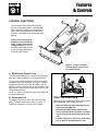
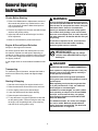
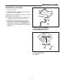
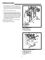
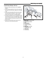
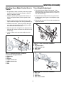
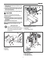
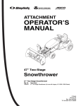
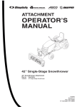
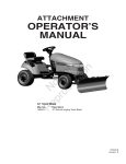
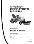
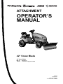
ATTACHMENT
OPERATOR’S
MANUAL
42” Snow Blade
42” Snow Blade
Mfg. No.
1694919
Description
42” Remote Angling Snow Blade
1732529
Revision 01
Rev. Date 02/2007
TP 100-4241-01-AT-SMA
Table of Contents
Troubleshooting, Adjustments & Service
Troubleshooting Chart .....................................8
Skid Shoe Adjustment .....................................9
Lift Adjustment.................................................9
Recommended Accessories ..............................1
Safety Rules & Information
Genera Warnings ............................................2
Operation on Slopes........................................2
Preparation ......................................................2
Operating Safety..............................................2
Initial Setup & Assembly
Install Hitch on to Tractor ...............................10
Install Snow Blade Lift Arm............................13
Attaching Pivot Assembly to Snow Blade ......14
Attaching Snow Blade to Tractor ...................14
Attaching Snow Blade Control Arm
To Tractor .......................................................15
Travel Height Adjustment...............................15
Features & Controls
Control Functions ............................................3
General Operating Instructions
Checks Before Starting....................................4
Engine & Ground Speed Selection..................4
Stopping & Starting .........................................4
Transporting.....................................................4
Changing Angle of the Blade...........................5
Snow Plowing Tips ..........................................5
Daily Storage ...................................................5
Off-Season Storage.........................................5
Removal
Snow Thrower Removal ................................16
Maintenance
Schedule for Normal Care ...............................7
General Lubrication .........................................7
NOTE: In these instructions, “left” and “right” are
referred to as seen from the operating position.
Recommended Accessories
For best performance, it is recommended to use tire chains and two rear wheel weights. A rear-mounted weight
carrier can also be added for additional traction. The maximum weight added to the tractor should not exceed 35
lbs. per wheel, plus 66 additional pounds in the rear weight box.
For operation on slopes greater than 15% (8.5°), Quick Tach Weights, tire chains, and wheel weights are recommended. Never operate on slopes greater than 17.6% (10°).
1
Safety Rules
& Information
Read these safety rules and follow them closely. Failure to obey these rules could result in loss of control
of unit, severe personal injury or death to you, or bystanders, or damage to property or equipment.
The triangle
in text signifies important cautions or warnings which must be followed.
PREPARATION
GENERAL WARNINGS
● Disengage the PTO before making any adjustments.
● Never attempt to make any adjustments while engine
is running.
● Thoroughly inspect the area where the dozer is to be
operated and remove all foreign objects.
● Adjust the skid shoe height to clear gravel or crushed
stone surface. See the Adjustments section for procedure.
● Know the tractor controls and how to stop quickly.
READ THE TRACTOR OPERATOR’S MANUAL.
● Read this manual and the tractor Operator’s Manual
carefully. Be thoroughly familiar with the controls and
the proper use of the equipment.
● Never allow children to operate the machine. Do not
allow adults to operate it without proper instruction.
● Do not carry passengers.
● Use only attachments or accessories designed for
your machine. See your dealer for a complete list of
recommended attachments or accessories.
● Keep the area of operation clear of all persons, particularly small children, and pets.
● Never direct discharge towards bystanders.
● Make sure all hardware is secure and that dozer
blade is in good operating condition.
● Check to be sure all safety devices and shields are in
place.
● Check that all adjustments are correct before using
this unit.
● Gasoline is highly flammable. Follow all precautions
listed in your tractor’s operator’s manual.
● Always wear eye protection while operating and performing adjustments to protect eyes from debris
thrown by the dozer.
● When cleaning, repairing, or inspecting the unit make
sure all moving parts have stopped. Disconnect and
secure the spark plug wires and remove the key to
prevent accidental starting.
OPERATING SAFETY
● Always clear snow up and down the face of slopes,
never across the face. Exercise extreme caution
when changing direction on slopes. Do not attempt to
clear steep slopes.
● Exercise extreme caution when operating on, or
crossing, gravel drives, walks or roads. Stay alert for
hidden hazards or traffic.
● After striking an object or if unit starts to vibrate
abnormally, stop the engine and remove the key.
Check for the cause and any damage before restarting. Before any inspection, make sure all moving
parts have stopped.
● Take all possible precautions before leaving operator’s position. Lower the attachment, set the parking
brake, stop the engine and remove the key.
● Never operate near glass enclosures, automobiles,
window wells, dropoffs, etc.
● Do not put hands or feet near or under the dozer
blade. Keep clear of the dozer blade at all times.
● Do not overload machine capacity by attempting to
clear too much material at too fast a rate.
● Never operate unit at high transport speeds on slippery surfaces. Use care when travelling in reverse.
● Never operate the dozer blade without good visibility
or light. Always be sure your feet are properly placed
on the footrests and keep a firm hold on the steering
wheel.
● Do not run the engine indoors.
● Never allow anyone in front of the unit.
DANGER
OPERATING ON SLOPES
CAN BE DANGEROUS
For operation on slopes greater than 15% (8.5°),
weight box, tire chains, and wheel weights are
recommended. NEVER OPERATE ON SLOPES
GREATER THAN 17.6% (10°).
TP-600-4159-01-UV-SMAN
2
Features
& Controls
B
CONTROL FUNCTIONS
A
The information below briefly describes the
function of individual controls. Operating the
tractor and dozer require the combined use of
these controls and additional controls whose
operation is described in the tractor Operator’s
Manual.
Please Take a moment and
familiarize yourself with the
name, location, and function
of these controls so that you
will better understand the safety and operating instructions
provided in this manual.
Figure 1. Control Locations
A. Blade Angle Control Lever
B. Attachment Lift
A. Blade Angle Control Lever
The blade angle release lever controls a spring-loaded
plate which locks the blade in one of three positions.
Turn the lever counterclockwise to release the angling
mechanism and move the blade left or right. Push the
angling lever forward fully to lock the blade in the left
position. Pull the lever fully back to lock the blade in the
right position. Move the lever slowly past center to lock
in the centered position.
NOTE: It is easier to change the angle of the blade with
the attachment raised.
B. Attachment Lift
TRACTOR CONTROLS
The attachment lift lever raises and lowers the dozer
blade. To RAISE attachment pull back on lever. To
LOWER an attachment, move the lever forward.
Before you begin operating the tractor with the dozer
blade attachment, make certain you have:
• Read and understood the instructions in the
tractor Operator’s Manual.
• Become thoroughly familiar with all of the
tractor controls and their operation, including
how to safely and properly start and stop the
unit.
• Practice driving in an open area—without dozing—to become accustomed to the unit.
3
General Operating
Instructions
Checks Before Starting
WARNING
1. Refer to the Maintenance & Adjustments sections of
this manual and perform any needed service. Also,
refer to the tractor Operator’s Manual and perform
any required service.
Perform the Safety System Interlock test found in
your tractor Operator’s Manual. If tractor does not
pass the test, do not operate the tractor. See your
authorized dealer. Under no circumstances
should you attempt to defeat the safety system.
2. Remove any objects from the work area which might
interfere with plowing activity.
Use caution when plowing a snow covered area.
Snow can cover objects such as curbs, drop-offs,
and other obstacles. Be familiar with the area you
are plowing.
3. Adjust the skid shoes to desired height. See Skid
Shoe Adjustment.
4. Make sure all hardware is present and secure.
To prevent an explosion or fire, never store the
tractor with fuel in the tank inside a building
where an ignition source is present.
Engine & Ground Speed Selection
Always run the engine at full throttle.
Set tractor speed to obtain the needed power to move
the material. Operate at a safe speed, depending on
conditions, so that you have complete control of the tractor. Rear wheel weights and chains are recommended
for slippery surfaces.
IMPORTANT NOTE
To prevent damage to the unit, always
raise the dozer blade BEFORE turning or
backing up.
A rear weight carrier is recommended for additional traction.
DANGER
OPERATING ON SLOPES CAN BE DANGEROUS
Transporting
Never operate on slopes greater than 17.6% (10°)
which is a rise of 3-1/2 feet (106cm) vertically in
10 feet (607cm) horizontally.
For maximum ground clearance, transport the blade to
and from work areas fully raised and angled straight
ahead.
Operate the unit at a slow ground speed when
driving onto slope. Avoid using brakes to control
ground speed.
Starting & Stopping
When operating on slopes that are greater than
15 % (8.5°) but less than 17.6%, use additional
wheel weights or counterweights.
1. Start the tractor engine. Set engine throttle to full.
2. Raise the attachment lift and travel to the work site.
3. Set the angling control to the desired angle.
In addition to counterweights, use extra caution
when operating on slopes. Drive UP and DOWN
the slope, never across the face, use caution
when changing directions and DO NOT START
OR STOP ON SLOPE.
4. Lower the attachment lift and begin plowing.
5. Raise the plow before backing up.
6. To stop the tractor, set ground speed to neutral and
set the parking brake. Before leaving the seat, stop
the engine, set the parking brake, remove the key,
and wait for all moving parts to stop.
For additional traction, tire chains and a weight
box can be added. Maximum weight added to
tractor should not exceed 35 lbs. per wheel and
100 additional lbs. in weight box.
4
General Operating Instructions
Changing Angle of the Blade:
walks, be careful not to tear up the grass buried
under snow next to the drive or sidewalk. Lift the
blade several inches off the ground to avoid damaging the grass.
See Figure 1 for location of Controls.
NOTE: It is easier to change the angle of the blade with
the attachment raised.
• Spinning tires with tire chains can leave unsightly
marks or permanent damage to asphalt or concrete
driveways or sidewalks. Avoid sudden stops or
starts.
1. Raise the attachment lift.
2. Turn the lever counterclockwise to release the
angling mechanism and move the blade left or right.
Push the angling lever forward fully to lock the blade
in the left position. Pull the lever fully back to lock the
blade in the right position. Move the lever slowly over
center to lock in the centered position.
Snow Plowing Tips
• Determine the best snow removal pattern before
beginning.
• Plan the pattern so that you avoid pushing snow onto
cleared areas.
• When land contour permits, it is best to travel in the
longest direction to minimize turning.
• In very deep or heavy snow, it may be necessary to
make the first pass with dozer blade partially raised,
then repeat each pass with the blade lowered to clear
the material left on the surface. Also, it may be necessary to clear less than the full width of the dozer
blade or reduce ground speed.
• Snow tends to freeze into solid banks when plowed
off a driveway or other large area. Because of this
you may want to plow snow several feet past the
edge of the drive to allow space for future plowing to
build up.
• If pushing snow past the edges of driveways or side-
Storage
Off-Season Storage
IMPORTANT NOTE
1. Remove dozer blade and hitch from the tractor.
Refer to Tractor Operator’s Manual for
important information concerning safely
storing your tractor.
2. Use water pressure or a brush to thoroughly clean
the dozer blade.
3. Paint, or lightly coat with oil, any area where paint
has been worn or chipped away.
Daily Storage
4. Lubricate the dozer blade.
1. Allow tractor engine to cool before storing in any
enclosure.
5. Store the dozer blade and hitch in a dry place.
2. After dozing or plowing jobs are completed, hose or
brush down the blade to remove excess dirt.
3. Lightly oil all pivot points. Coat bare metal surfaces to
prevent corrosion.
5
Notes
6
Maintenance
Schedule For Normal Care
General Lubrication
Lubricate the snow blade as shown in Figure 2. Where
an oil can is shown use 30 weight oil. Where a grease
gun is shown, use lithium grease. Lubricate the following
areas:
• Grease the blade pivot.
• Oil the blade lock pawl
• Apply grease to the plastic wear surface above the
bell crank and to the bell crank.
WARNING
To avoid serious injury, perform maintenance on
the unit only when the engine is stopped and all
moving parts have stopped. Always remove the
ignition key before beginning maintenance or
adjustments to prevent accidental starting of the
engine.
Figure 2. Lubrication Points
General Lubrication
Care Required
Schedule
Clean snow and ice from
the snow blade.
Lubricate snow blade.
After each use
Every 10 hours or at
least once a year.
7
Troubleshooting,
Adjustments, & Service
TROUBLESHOOTING
WARNING
While normal care and regular maintenance will extend
the life of your equipment, prolonged or constant use
may eventually require that service be performed to
allow it to continue operating properly. The troubleshooting guide below lists the most common problems, their
causes and remedies. See the information on the following pages for instructions on how to perform most of
these minor adjustments and service repairs yourself. If
you prefer, all of these procedures can be performed for
you by your local authorized dealer.
• To avoid serious injury, perform maintenance
on the tractor or snow blade only when the
engine is stopped and the parking brake
engaged.
• Always remove the ignition key, disconnect the
spark plug wire and fasten it away from the plug
before beginning the maintenance, to prevent
accidental starting of the engine.
PROBLEM
CAUSE/SOLUTION
1 Snow blade does not lock into position.
A. Clean ice or snow from lock and pivot mechanism.
B. Lubricate lock and pivot mechanism.
C. Check return spring.
2 Scraper bar does not clean down to
hard surface.
A. Skid shoes not properly adjusted. Adjust skid shoes.
B. Lift height out of adjustment. See ADJUSTMENTS section.
3. Snow blade picks up stones on
gravel drive.
A. Skid shoes not properly adjusted for ground surface.
Adjust skid shoes.
4 Tractor does not have sufficient traction.
A. Tractor too light at rear wheels. Use Quick Tach weights,
wheel weights, and tire chains.
5. Tractor not stable on sloping surfaces.
A. Ground speed too fast. Reduce speed.
B. Tractor not properly weighted. See Recommended
Accessories, page 1.
C. Slope grade too steep. See Safety Section. Use Quick Tach
weights, wheel weights, and tire chains.
6 Snow blade lifts hard.
A. Apply grease to plastic wear pad above bell crank and to the
bell crank.
B. Check lift assist spring.
8
Troubleshooting, Adjustments, & Service
Skid Shoe Adjustment
On smooth surfaces such as concrete or asphalt, the
scraper bar should scrape the surface. On surfaces such
as gravel, the scraper bar should be set high enough so
that it will not pick up debris.
A
1. Lower the snow blade and adjust the skid shoes to
achieve the correct plowing height.
2. Loosen the nuts (A, Figure 3) securing the skid shoes
(B).
B
3. Raise or lower the scraper bar to the desired height.
Use wood blocks to hold the snow blade in position.
Figure 3. Skid Shoe Adjustment
A – Lock Nut
B – Skid Shoe
4. Set the skid shoes so that they are in contact with the
ground and tighten the skid shoe nuts.
Lift Adjustment
In the fully raised position the attachment should be 4”-5”
off the ground.
LIFT HEIGHT ADJUSTMENT
1. Fully raise the snow blade. The snow blade should
be approximately 4”-5” off the ground. If not, go to
step 2.
2. Lower the snow blade to the ground.
C
3. Remove hairpin cotter pin (B, Figure 4) from the ball
joint (A) on the lift arm. Remove the lift arm from the
bell crank (C).
4. Loosen the ball joint lock nut (D) and rotate the ball
joint either counter clockwise to lower the travel
height or clockwise to increase the travel height.
Tighten the lock nut (D).
D
B
A
Figure 4. Travel Height Adjustment
A – Lift Arm Ball Joint
B – Hair pin
C – Bell Crank
D – Ball Joint Lock Nut
5. Reinstall the lift arm (A) onto the bell crank (C) and
secure with the hairpin cotter pin (B).
6. Raise the snow blade off the ground and check the
travel height.
7. Repeat as needed until the correct travel height
is set.
9
Initial Setup
& Assembly
20
2
4
1
21
18
6
25
3
17
12
2
5
7
19
2
2
9
8
2
15
13
16
10
22
12
13
23
24
Ref Qty
1
1
2
7
3
1
4
1
5
1
6
1
7
1
8
1
9
1
10
2
11
1
12
3
13
2
Description
Lift Assist Spring
Hair pin
Flat Washer
Lift Arm
Stand Off
Lock Washer
Bolt
Hitch Assembly
Bell Crank
Mounting Pin
Hitch Pivot Assembly
Bolt
Whiz Lock Nut
Ref Qty
14
1
15
1
16
1
17
1
18
2
19
2
20
1
21
1
22
2
23
2
24
2
25
1
Figure 5. Initial Setup
10
Description
Snow Blade Assembly
Spring
Eye Bolt
Lower Control Arm
Bolt
Flange Nut
Upper Control Arm
Control Arm Support Bracket
Eye bolt lock nut
Spacer
Washer
Flange Nut
Initial Setup & Assembly
Install Hitch on to Tractor
1. Remove mower deck.
2. Install the bell crank (A, Figure 6) through the front
holes (B) of the hitch assembly.
NOTE: Make sure that the Lift Arm connection is to the
right side of the hitch assembly.
3. Place hitch on floor in front of tractor, with the hitch
mounting arms towards the rear of the tractor.
B
4. On underside of tractor frame, insert hitch support
shaft (A, Figure 7) as shown and secure, with the
cotter pin (B) on inside of frame. IMPORTANT – the
cotter pin must be located along the inside edge of the
tractor frame.
A
Figure 6. Bell Crank Installation
A. Chute Rotator Drive Cover Bolt
B. Chute Rotator Drive Cover
A
B
Figure 7. Hitch Support Shaft
A. Hitch Support Shaft
B. Cotter pin
11
Initial Setup & Assembly
5. Slide hitch (A, Figure 8) under tractor and lift to slide
hitch mounting arms (C) over hitch support shaft (B).
6. At front of the machine, locate and remove the lower
hitch latch pin (D, Figure 9) from the hitch assembly
(C).
7. Turn the front wheels fully to the left.
8. Lift the hitch (C) and place the upper hitch latch pin
(A) onto the tractor frame support fingers. From the
left side of the tractor, slide lower hitch latch pin (D)
through the mounting hole in hitch frame, underneath
the tractor frame support fingers (B) and through the
final mounting hole in hitch frame locking the hitch
onto the tractor frame. Secure the lower hitch latch
pin (D) with the quick clip (E).
NOTE: Keep the handle portion of the hitch latch pin
towards the front of the tractor.
C
B
9. Hitch installation is now complete.
A
Figure 8. Hitch Installation
A. Hitch Assembly
B. Hitch Support Shaft
C. Hitch Mounting Arms
B
D
E
A
C
B
Figure 9. Hitch Latch Pin Installation
A. Upper Hitch Latch Pin
B. Frame Support Fingers
C. Hitch Assembly
D. Lower Hitch Latch Pin
E. Hair pin
12
Initial Setup & Assembly
Install Snow Blade Lift Arm
1. Move the mower deck lift arm to the “LOWERED”
position.
2. Install the brass stand-off (A, Figure 10) at the top of
the mower deck lift arm (B), using bolt (C) and washer (D).
D
3. Install the lift assist spring (E) from the rear edge of
the tractor frame to the brass “C” clip (F) on the
mower deck lift arm (B), if not already installed.
B A
G
G
K
J
C
4. Slide the snow blade lift arm (G) underneath the tractor and attach the lift arm to the stand-off (A). Secure
the lift arm with the hair pin (H). NOTE: Make sure to
position the washer (D) between the hair pin (H) and
the lift arm (G).
F
H
E
H
Figure 10. Belt Tension Lever
A. Stand Off
B. Mower Deck Lift Arm
C. Bolt
D. Lock Washer
E. Lift Assist Spring
F. C-Clip
G. Snow Blade Lift Arm
H .Hair pin
I. Lift Arm Ball Joint
J. Bell Crank
K. Flat Washer
5. Attach the lower ball joint (I) to the bell crank (J).
Secure the lift arm with the hair pin (H).
13
I
Initial Setup & Assembly
Attaching Pivot Assembly to Snow
Blade
E
1. Attach the pivot assembly (A, Figure 11) to the snow
blade (C) using bolt and nut (B).
F
D
B
A
2. Attach the tension spring (D) to the pivot assembly
(A) and then to the eyebolt (E).
H
3. Tighten the eyebolt nut (F) to apply tension to the
spring. Tighten lock nut (G) when the proper spring
tension is set.
I
G
B
C
Figure 11. Snow Blade Assembly
A. Pivot Assembly
B. Whiz Lock Nut
C. Snow Blade Assembly
D. Tension Spring
E. Eyebolt
F. Nut
G. Capscrew
H. Flat Washer
I. Spacer
Attaching Snow Blade to Tractor
1. Position snow blade assembly in front of tractor.
2. Remove the mounting pin (A, Figure 12) and quick
clip (B) from the snow blade.
A
NOTE: Make sure that the bell crank (C) is rotated forward before installing the snow blade assembly.
3. Align mounting holes on snow blade frame with the
mounting holes in the hitch.
4. Insert mounting pin (A) and secure with hair pin (B).
C
B
Figure 12. Attaching Snow Blade to Hitch
A. Mounting Pin
B. Hair Pin
C. Bell Crank
14
Initial Setup & Assembly
Attaching Snow Blade Contort Arm to
Tractor
Travel Height Adjustment
1. On right side of tractor, install the control arm support
bracket (A, Figure 13) using the flange nut (B) and
bolt (C) to the tractor frame.
1. Fully raise the snow blade off the ground. If the
transport height is not correct, lower the snow blade
to the ground and remove the lift arm (A, Figure 15)
from the bell crank (C).
2. Install the eyebolt (D) through the hole at the top of
the lift arm support bracket, with the eyebolt to the
outside.
2. Loosen the lift arm ball joint lock nut (D) and rotate
the ball joint (A) either right or left to adjust the proper lift height.
3. Attach the lower portion of the control arm (F) to the
upper control arm using the lock nuts (G) and bolts (H).
3. Reinstall and secure the lift arm and test adjustment.
Repeat as needed.
4. Install the lock bolt (A, Figure 14)) through the upper
snow blade adjustment arm (B), securing the adjustment arm to the snow blade frame.
A
5. Slide the control arm through the two adjustment arm
ball joints (D). Secure the control arm with the four (4)
hair pins (E).
C
6. Lower the blade to the ground and adjust the skid
shoes.
B
E
D
D
E
H
F
B
A
C
Figure 14. Lower Control Arm Installation
A. Bolt
B. Adjustment Arm
C. Lower Control Arm
D. Ball Joints
E. Hair pins
G
Figure 13. Blade Control Arm Installation
A. Control Arm Support Bracket
B. Flange Nut
C. Bolt
D. Eyebolt
E. Upper Control Arm
F. Lower Control Arm
G. Nut
H. Bolt
C
D
B
A
Figure 15. Lower Control Arm Installation
A. Ball Joint
B. Hair pin
C. Bell Crank
D. Ball Joint Lock Nut
15
Removal
Snow Blade Removal
CAUTION
Make sure to shut off the engine and lock the
tractor brakes or block the rear wheels before
beginning the snow blade removal process.
A
1. Lower the snow blade to the ground.
2. Remove the four (4) hair pins (C, Figure 16) from the
control arm (A) and remove the control arm from the
snow blade assembly.
B
3. Remove the control arm from the tractor.
C
NOTE: The control arm support bracket can be left on the
tractor.
Figure 16. Control Arm Removal
A. Control Arm
B. Ball Joints
C. Hair pins
4. Remove the bell crank hair pin (A, Figure 17) and
remove the snow blade lift arm (B) from the bell crank
(C).
5. Remove lift arm (B) from the mower deck lift arm by
removing the hairpin cotter pin (D) from the stand off
(F). Fully remove the snow blade lift arm (B) from the
tractor.
NOTE: Leave the stand off attached to the mower deck
lift arm.
F
B
B
E
C
A
D
B
Figure 17. Control Arm Removal
A. Hair pin
B. Snow Blade Lift Rod
C. Bell Crank
D. Hair pin
E. Flat Washer
F. Standoff
16
Removal
6. Remove the snow blade hair pin (B, Figure 18) and
mounting pin (A).
C
A
7. Slide the snow blade assembly away from the tractor.
8. Remove the lower latch pin (A, Figure 19) from the
front of the hitch assembly.
9. Lift the hitch assembly off of the support fingers (C).
CAUTION
B
Make sure to support the front of the hitch
assembly as is will be loose when the latch pin
has been removed.
10. Slide the hitch assembly (A, Figure 20) forwards until
the hitch mounting arms (C) are free of the hitch support shaft (B).
B
11. Slide the hitch from under the tractor.
NOTE: The hitch support shaft (B) may be left in position
and will not interfere with the operation of the lawn
mower deck.
IMPORTANT NOTE
Figure 19. Remove Hitch Latch Pin
A. Lower Latch Pin
B. Quick Clip
C. Frame Support Fingers
Inspect the snow blade assembly, hitch
assembly, and all component parts for signs of
wear or damage. Have these items repaired or
serviced before reinstalling the snow blade
onto the tractor.
A
C
B
C
Figure 18. Removing Snow Blade from Hitch
A. Mounting Pin
B. Hair pin
C. Bell Crank
B
A
Figure 20. Hitch Removal
A. Hitch Assembly
B. Hitch Support Shaft
C. Hitch Mounting Arms
17
MANUFACTURING, INC.
500 N Spring Street / PO Box 997
Port Washington, WI 53074-0997
PRODUCTS
535 Macon Street
McDonough, GA 30253
www.SimplicityMfg.com
www.Snapper.com
500 N Spring Street / PO Box 997
Port Washington, WI 53074-0997
500 N Spring Street / PO Box 997
Port Washington, WI 53074-0997
www.MasseyLawn.com
AGCOLawn.com
Briggs & Stratton Yard Power Products Group
Copyright © 2007 Briggs & Stratton Corporation
Milwaukee, WI USA. All Rights Reserved