1
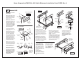
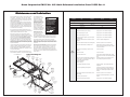
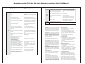
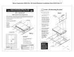
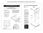
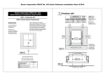
Braun Corporation FMVSS No. 403 Quick Reference Installation Sheet 32553 Rev. A
1 Locate Lift Mounting Brackets
NHTSA Vehicle Physical Requirements
Mounting Bracket Requirements:
A maximum distance of 16" from the
outermost mounting bracket to the
end of the cassette.
All four mounting brackets must be
connected to the framerails.
CH
All-thread
Mounting
Brackets
Figure A
16
Ma ”
xim
u
m
A
855
A
Figure B
OSS
E
N
IN
G
P
90
O
"
3/8
22"
3/8
22-
All-Thread
Mounting
Brackets
Engage Platform Manual
Release System: The lift
cable-activated platform
manual release is disengaged
during shipment to prevent
potential drive chain stretch.
Handle the lift with care. Engage manual release before
attempting to install (raise, tilt
or move) the lift.
Door Opening Dimensions
Vehicle lift access door opening
must meet specified dimensions.
C
ME
5. Clamp the mounting brackets
securely in place (all-thread
studs must be vertical).
LE R
HIC BE
VE MEM
SIS
AS
CH
B
FRA
3. Transfer center point to the
vehicle frame. Using a frontto-rear framing member as a
guide, transfer the center point
across chassis to opposite side
front-to-rear framing member
(must be 90° to door opening).
Lift mounting bracket positions
are based on this center line.
4. Measure 22-3/8" to left and
right of the center line to
achieve the 44-3/4" center-tocenter spacing of all-thread
mounting studs.
LE R
HIC BE
VE MEM
SIS
AS
E
ACR
O
Alternative floor structures are allowed
providing the installed lift system passes all FMVSS 403 requirements.
2. Locate center of door opening
(between doors). Mark the
center point.
TER
ICL
D
All vehicles with a GVW over 6000 lbs.
and with unmodified OEM framerails.
“DOT - Public Use Lift” verifies this platform lift
meets the “public use lift” requirements of FMVSS
No. 403. This lift may be installed on all vehicles
appropriate for the size and weight of the lift, but
must be installed on buses, school buses, and
multi-purpose passenger vehicles other than
motor homes with a gross vehicle weight rating
(GVWR) that exceeds 4,536 kg (10,000 lb).
N
RI
TE NING
N
CE OPE
OR
O
D
CL
CEN
VEH
1. Open both doors to 90°.
Vehicle Requirements:
Figure C
Locate All-Thread Mounting
Brackets
“DOT — Public Use Lift”
B
C
Minimum Clear Door
Opening Height
Clear Door Opening Width
Maximum Floor-to-Ground
NA
43-1/2"
50"
WARNING
Engage manual
release before
attempting to install
(raise, tilt or move)
lift. Failure to do so
may result in serious
bodily injury and/or
property damage.
O
Rev: A
R
Braun Corporation FMVSS No. 403
Quick Reference Installation Sheet 32253
WARN
ING
Push
manuall
T-handle
and
y
lock out movein fully
to
before
Failure
platform
engage
and
result to driving
platform
in
deploym
in lock
vehicle.
platform
platform unintend
result ent.
ed may
Unintend
platform
and/orin deploym
serious
property ent ed
may
bodily
damageinjury
Do
not
.
remov
e!
81823
"
3/4
44-
Braun Corporation FMVSS No. 403 Quick Reference Installation Sheet 32553 Rev. A
2 Secure Lift
Figure G
LE R
HIC BE
VE MEM
SIS
S
A
CH
“Channel” Framing Member
Attach Mounting Brackets to
Vehicle Frame
Mounting bolts must be routed
horizontally through the vertical face of the “L” brackets and
framing members as shown in
Figures D, E and F.
Eight 3/8-16 x 1-1/2" hex bolts
are supplied for bolting the allthread mounting brackets to the
frame (two per bracket). Oval
slotted mounting holes are provided in the mounting brackets
to allow adjustment. Carefully
drill 25/64" (.390") diameter
mounting holes at the center of
the oval mounting slots.
Hex
Nut
Figure D
LE R
HIC BE
VE MEM
SIS
AS
CH
Lock
Washer
LE R
HIC BE
VE MEM
SIS
AS
CH
Flat
Washer
Lift
Housing
All-Thread
Stud
Lift
Clamp
Jam Nuts
All-Thread
Bracket
Flat
Washer
3/8-16 x 1-1/2"
Hex Bolt
Figure I
Lift Clamp
Jam Nuts
Lift
Housing
Jam Nuts
Flat Washer
Lift Clamp
Align mounting clamps
with all-thread studs.
“Box” Framing Member
Figure H
Flat Washer
WARN
ING
Push
manually
T-handle
and
Channel Frame Applications:
Secure mounting bolts as specified in Figure D.
Box Frame Spacers: Position
tubing spacers as shown at
right to prevent collapsing the
box frame. Carefully drill a
25/64" (.390") diameter mounting hole through one side of the
box frame. Drill a 5/8" (.625")
diameter hole through the
opposite side of box frame to
allow installation of spacer. Cut
spacer tubing to length (equal
to thickness of box frame).
Note: A longer 3/8-16 bolt will
be required for box frame applications. Secure mounting bolts
as specified in Figures E and F.
lock out movein fully
to
before
Failure
platform
engage
and
result to driving
platform
in
deployme
in lock
vehicle.
platform
platform unintend
nt.
result
ed may
Unintend
platform
and/orin deployme
serious
property nt ed
may
bodily
damage.injury
Do
not
Figure E
All-Thread
Bracket
Hex
Flat
Nut
Washer
VE
BO HICLE
XF
RA
ME
Lock
Washer
3/8-16 x 1-1/2"
Hex Bolt
Flat Washer
3/8-16
Hex Bolt
All-Thread
Bracket
Spacer
25/64"
Diameter
Hole
Box
Framing
Member
Hex
Nut
All fasteners must meet FMVSS 571.403 Section 6.3.
Shipping Block Removal:
Wood blocks are placed in the
lift housing to prevent lift damage during shipment. Remove
shipping blocks from platform
and carriage before running
(activating) lift. Refer to
Shipping Block Removal
Instruction 28942.
Flat Washer
Spacer
Assembled
“Box” Framing Member
Figure F
Jam Nuts
81823
Thread two 3/4" hex jam nuts fully
onto each mounting bracket all-thread
stud. Place one large diameter flat
washer onto each all-thread stud (use
tape to hold in place). See Figures G
and H.
Carefully position lift under vehicle
(aligned with mounting brackets).
Position (slide) the four lift mounting
clamps along the sides of the lift housing until aligned with mounting bracket
all-thread studs. See Figure G.
5/8"
Diameter
Hole
Flat
Washer
remove
!
Position and secure lift.
Lock
Washer
Spacer Tubing
Length: Equal
to thickness of
box frame.
Carefully raise lift into position as high
as possible (height adjustment outlined
below). Place one large diameter flat
washer onto each mounting bracket allthread stud. Thread two 3/4" hex jam
nuts fully onto each all-thread stud (up
against lift mounting clamp).
B
Height Adjustment
The lift housing must be
aligned with vehicle chassis. Adjust the 3/4" hex jam
nuts on the all-thread mounting studs at all 4 corners of
the lift until dimensions A, B, C
and D are equal (within 1/16").
See Figure J.
In-Out Positioning
Position the lift to achieve a 2”
overlap between the deployed
inboard barrier and the vehicle
floor.
Shift lift and mounting brackets
left-to-right as needed (lift must
be centered in door opening).
Tighten the 3/8" bolts securing
mounting brackets to the frame.
Torque Specifications: 25 to 30
foot pounds.
Note: The two outboard mounting
brackets should be positioned a
maximum of 16” from the end of the
cassette. See Figure J.
Dimensions
A, B, C and D
must be equal
(within 1/16").
LE R
HIC BE
VE MEM
IS
SS
A
CH
Tighten upper set of 3/4" hex
jam nuts (with flat washer)
down to the lift mounting
clamps. Tighten jam nuts.
Torque Specifications: 100
to 120 foot pounds.
C
LE R
HIC BE
VE MEM
SIS
AS
CH
A
D
16
Ma ”
x im
Figure J
um
Braun Corporation FMVSS No. 403 Quick Reference Installation Sheet 32553 Rev. A
3 Electrical, Hydraulic and Interlock
Cable-activated Manual
Release: The T-handle must
be mounted inside the vehicle.
The cable must operate freely
(no kinks or bends). Warning
tag 81823 must remain attached
to the handle. Remove handle
for installation.
Cable-activated
Manual Release
(from lift)
7/8" Diameter
Mounting Hole
Vehicle Battery Ground Cable:
One ground cable is pump
mounted. Route this ground cable
through the floor grommet and connect to a vehicle framing member
(see Figure L).
A ground cable (minimum 2 gauge)
must be connected from vehicle
battery negative post to the same
vehicle framing member the pump
ground cable is attached to.
5/16"
External Tooth
Star Washer
Note: Seal the
floor cable and
hose grommet
following installation procedures
(fill with silicone).
L
Ca ead
bl
e
rC
ab
le
Install Circuit
Sentry as shown
in Figure M. Attach power cable
and lead cable as
detailed.
Connect red positive
(+) power cable here
(from Circuit Sentry).
Figure M
Install black jumper wire
last. Install the black jumper
wire in pump Terminal Strip
terminals 6 and 9 after all
other electrical connections
have been made (see Panel
4). The jumper wire supplies
power to the circuit board.
Check floor level and inner roll
stop adjustments as detailed
in Panel 4 before operating
lift with electric pump.
Ne
g.
Vehicle and Lift Interlocks
Optional Interlock Kits
The pump module is equipped
with a lift interface 9-circuit
connector (female socket).
A mating 9-circuit connector
(male plug) is supplied.
Universal Interlock Kit
30940K is available
for easy interface with
vehicle OEM electronic
signals.
Figure N
1
Disconnect
and remove
eye terminal
L
To
s.
1
M 2"
ax
.
we
Po
ift
To meet minimum
NHTSA requirements,
connect to vehicle interlock harness as outlined
in Figure N (Steps 1-4).
Note: All
wiring harness
connections
must be
inside the
vehicle.
2
Disconnect
Note: Detailed installation instructions are supplied with interlock kits.
g
i rin
t W es
Lif ness
n
i
Ma Har
m
lar
t
eA
ob
Ma
Str hold
s
hts )
e
g
r
Li
ed
Th
rm label
o
f
t
Pla wires
(
Instrument Panel Display
Kit 30938K provides an
LED Panel Display that
interfaces with Braun
Universal Interlock Kit
30940K.
4
Connect
In
te
Connect harnesses to
mating harnesses at
pump (labeled). Detailed
installation instructions
supplied with kits.
Threshold Warning Sensor:
k
Route two main wiring
harnesses from lift through
floor grommet to pump
module. Connect to mating harnesses at pump.
Beeper/Strobe Alarm
and Platform Lights:
oc
Housing/Carriage Harnesses:
rl
Figure L
Ground Cable Mounting
Thread
Cutting
Screw
Ground Cable Corrosion:
When mounting ground
cables, remove undercoating, dirt, rust, etc. from
framing member around
mounting holes. Apply
protective coating to mounting holes to prevent corrosion. Failure to do so will
void warranty of certain
electrical components.
Route hydraulic
hose assembly
through floor
grommet to quickdisconnect fitting at
lift. Connect hose.
Po
To
Ch
is
ass
Remove the plug
from 1/4" diameter
clear vent tube.
See Figure N.
Note:
Remove
plug from
vent tube.
Reinforcement
“L” Bracket
Pump Ground Cable:
9/32"
Diameter
Pilot Hole
Through-Floor
Cable and Hose
Grommet
(3" Diameter
Mounting Hole)
Circuit Sentry:
B
at
.
Mo
u
Pu nt
Ve mp
rtic
al
Pu
m
mu p
s
fac t
e
Ou
t
Lock
Washer
Note: Locate and drill pump
module mounting holes, floor
grommet 3" diameter hole and
manual release 7/8" diameter
hole before mounting pump.
mp
Pu ting
un et
o
M ck
Bra
Hydraulics:
1/
8"
Pl x 4"
as x
tic 4
"
Check under vehicle for
obstructions before drilling,
cutting holes or installing
floor mounting hardware.
1/4-20 x 3/8"
Hex Screws
Jumper Wire
Figure K
Ci
Se rcu
nt it
ry
Mount reinforcement “L” bracket
to pump mounting bracket as
shown in Figure K. Secure
pump mounting bracket to floor
using four 5/16" lag bolts.
Mi
n
1-3 .
/4”
to
Wa
ll
A
ux
.
5/16"
Lag Bolts
(typical - 4)
Pump Module Mounting
3
Connect harness to mating harness at pump module (labeled).
Mat must be installed on a flat
rigid surface. Inboard edge of mat
must be minimum 18" from edge
of finished floor or stepwell.
Connect vehicle
interlock signal wires
LIF
T
SI STO
w/L GNA WE
D
igh L
VE
tB
HIC
lue
LE
)
S
(Gr IGN SEC
UR
ey/ AL
E
Re
d)
(Ye
llo
Braun Corporation FMVSS No. 403 Quick Reference Installation Sheet 32553 Rev. A
5
4 Door Operators/Switch, Terminal
FMVSS 403/404 Certification Checklist
Strip and Floor Level Adjustment
Install optional
power door operators as detailed
in the instructions
supplied with
door operator kit.
Figure O
Route the wires
to the pump module and connect
to the terminal
strip as shown in
Figure P.
To Door Openers
“Open” Trigger
1 2 3 4 5 6 7 8 9 10
Black
Jumper
Power Door Operators
The pump-mounted
terminal strip provides
additional inputs and
outputs that can be
used for optional door
operators, beepers,
interlocks, etc. - as
well as the door safety
switch. The black
jumper wire must be
installed in terminals 6
and 9 to supply power
to the circuit board.
1 2 3 4 5 6 7 8 9 10
Terminal Strip
Orange
Door Cutout
Door Cutout
Black
Red
Blue
To Door Openers
“Close” Trigger
Visual and Audible
Threshold Warning
DOT — Public Use Lift
Public use vehicle manufacturers
are responsible for complying with
the lift lighting requirements in Federal Motor Vehicle Safety Standard
No. 404, Platform Lift Installation in
Motor Vehicles (49 CFR 571.404).
C_SW
O_RL
N/C
Platform
Lighting
IN_LK
12_V
PWR
FOLD
GND
UNFOLD
UP
Threshold
Area
DOWN
F_LV
O_SW
C_RL
Figure P
ld
ho at
res r M
Th enso
S
Inner
Roll Stop
Floor Level and Inner Roll Stop Adjustments
Achieving proper floor level positioning of the
platform and inner roll stop requires a combination of Floor Level switch adjustment and inner
roll stop adjustment. Both are factory set but
must be inspected during installation procedures
(will vary per vehicle application).
Ensure the lift is positioned and secured as specified above (panels 1 and 2). Adjust the Floor
Level switch first (detailed below). Then, adjust
the inner roll stop as detailed in the service manual
(adjust only if necessary). The inner roll stop must
rest properly on the vehicle floor for wheelchair
entry and exit.
JK
A
Dual
Outer Barrier
Platform
Floor Level Switch
Floor Level Cam
Floor Level Switch
The Floor Level switch stops upward travel of
the platform during the Up function (activated
by the torque tube-mounted Floor Level cam).
Position the lift platform 1" above floor level
using the manual operation system (detailed on opposite side of this sheet). Loosen
the clamp securing the torque tube-mounted
Floor Level cam. Rotate the cam until the
Floor Level switch is activated (cam depresses
switch).
Note: Check the floor level position of the platform and the inner roll stop after powering the
pump. Hydraulic pressure may affect platform
height slightly. Fine tuning adjustment (tweaking) of the Floor Level switch may be required.
The operations listed below must be
functionally verified.
Vehicle movement is prevented unless the lift
door is closed, ensuring the lift is stowed.
Lift operation shall be prevented unless the
vehicle is stopped and vehicle movement is
prevented.
Platform movement is prohibited beyond
the position where the inner roll stop is fully
deployed (up).
The platform will not fold/stow if occupied.
Torque Tube
Cam depressing switch.
The outer barrier will not raise if occupied.
A visual and audible warning will activate if
the threshold area is occupied when the platform is at least one inch below floor level.
The inner roll stop will not raise if occupied.
Lift platform movement shall be interrupted
unless the outer barrier is deployed (up).
Braun Corporation FMVSS No. 403 Quick Reference Installation Sheet 32553 Rev. A
Lift Operating Instructions
Note: The instructions outlined here are applicable for
“Public-Use” NUVL lift models equipped with dual
WARNING
Whenever a
passenger is on the
platform, the:
• Passenger must
be positioned
fully inside yellow
boundaries
• Wheelchair brakes
must be locked
• Inner roll stop and
outer barrier must
be up.
Failure to do so may
result in serious
bodily injury and/or
property damage.
folding handrails and a dual
outer barrier system.
Before lift operation, park the
vehicle on a level surface, away
from vehicular traffic. Place the
vehicle transmission in “Park”
and engage the parking brake.
Open manual doors fully, being
certain the doors are secured in
the fully open position.
It is the responsibility of the lift
operator (attendant) to properly open, secure and close the
vehicle lift doors, to activate any
auxiliary interlock (if equipped),
to load and unload the wheelchair passenger (or standee) on
and off the lift platform, and to
properly activate all lift functions.
In event of power or equipment
failure, refer to the Manual Operating Instructions section.
Handrails and Dual Outer Barrier:
The folding handrails and tall outer
barrier are manually operated. The
spring-loaded outer barrier (tall barrier)
and the handrails rest on the platform
when the lift is not in use. The outer
barrier must be raised to the vertical
position and the handrails must be
lifted to the vertical position whenever
a passenger is on the platform.
The tall outer barrier and the handrails
must be folded down to the platform
(horizontal) position before stowing
the lift. The handrails fold down onto
the outer barrier to secure the barrier
in the horizontal position.
Each handrail is secured with two detent pins (one pin at the base of each
vertical support tube). The detent pins
must be removed before the handrails
can be folded or unfolded and the
detent pins must be reinserted after
folding or unfolding the handrails.
Hand-held Pendant Control:
The hand-held attendent's pendant control is
equipped with four push button switches (DOOR,
STOW, DOWN and UP). The momentary switches
activate the automatic lift functions. Simply press
the switch labeled for the intended function.
DOOR
DOWN
STOW
UP
When there is power to the lift, the lift function labels
illuminate to identify the functions.
From ground level, the UP function will first automatically raise (rotate) the outer barriers to the
upright (vertical) position. The platform then raises
to floor level position. Note: The lift will not raise
if the outer barrier is not in the UP position (built-in
safety feature).
DOWN: The DOWN function lowers the platform
to ground level and then unfolds the outer barriers
to the ramp (horizontal) position. From the stowed
position, the lift will extend fully and then lower.
OPEN DOOR(S) AND SECURE
Manually open door(s) fully and
secure.
TO LOAD PASSENGER:
1. Read Notes below! Load passenger onto platform and lock
wheelchair brakes.
TO DEPLOY PLATFORM:
1. Stand clear and press the UP
switch until the platform extends
fully. Release switch.
Note: Outer barrier must be fully
unfolded (ramp position) until the
entire wheelchair (or standee) has
crossed the outer barrier.
2. Pull handrail detent pins, lift
handrails up to vertical position and
reinsert detent pins.
Note: Passenger must be
positioned fully inside yellow
boundaries.
3. Lift outer barrier to vertical position.
2. Press UP switch to fold outer barrier UP fully (vertical), raise the
platform to floor level and unfold
inner roll stop to floor level. Release switch.
4. Press the UP switch until the platform stops (raises to floor level)
and inner roll stop unfolds to floor
level. Release switch.
TO UNLOAD PASSENGER:
1. Read Note below! Load passenger onto platform and lock
wheelchair brakes.
Note: Passenger must be
positioned fully inside yellow
boundaries and outer barrier must
be UP.
2. Press DOWN switch until the entire
platform reaches ground level and
the outer barrier unfolds fully
(ramp position). Release switch.
Control Switch Functions:
UP: From the stowed position, pressing the UP
switch deploys (extends) the platform fully. Release
the UP switch once the platform has extended fully
in order to deploy the outer barrier and handrails.
The platform will continue to raise to floor level if the
UP switch is not released and handrail procedures
may be more difficult (floor level height varies per
vehicle). Pull the handrail detent pins and lift the
handrails to the vertical position. Reinsert the detent pins after the handrails are raised. Lift the outer
barrier to the vertical position. Press the UP switch
until the platform stops (raises to floor level), and the
inner roll stop unfolds to floor level.
Lift Operating Instructions
3. Unlock wheelchair brakes and
unload passenger from platform.
TO STOW PLATFORM:
1. Fold outer barrier down to platform
(horizontal) position.
2. Pull handrail detent pins, fold handrails down to platform (horizontal)
position and reinsert detent pins.
3. Press STOW switch until platform
stops (retracts fully). Release
switch.
CLOSE DOOR(S)
3. Unlock wheelchair brakes and
unload passenger from platform.
STOW: The STOW function raises or lowers the
platform to stow level and then moves the platform
inward (retracts) to the stow position. Handrails
and Outer Barrier: The tall outer barrier and the
handrails must be folded down to the platform
(horizontal) position before stowing (retracting)
the platform. The handrail detent pins must be reinserted before stowing the platform also. Note:
The lift will not stow with weight on the platform
(built-in safety feature).
DOOR CLOSE: This function is not applicable
for “Public-Use” NUVL lift models (manual door
system and attendant operated lift).
Note: If any of these functions do not occur as
described, discontinue lift use immediately and
contact your sales representative or call The
Braun Corporation at 1-800-THE LIFT®. One of
our national Product Support representatives will
direct you to an authorized service repairman who
will inspect your lift.
Note: Outer barrier must be fully
unfolded (ramp position) until the
entire wheelchair (or standee) has
crossed the outer barrier.
Manually close door(s) fully.
Braun Corporation FMVSS No. 403 Quick Reference Installation Sheet 32553 Rev. A
Manual Operating Instructions
POWER
PACK
Valve
Note: Location of power
pack and T-handle varies.
1. Pull T-Handle.
2. Turn T-Handle to lock platform in released position.
3. Pull platform out.
4. Turn T-Handle.
5. Push T-Handle in.
6. Turn T-Handle to lock platform in engaged position.
WAR
NIN
G
Pu
sh
ma T-h
andnuallyandle
loc out mo in ful
ve
Faik bef to eng pla ly and
ore
reslure to driage tform
depult in loc vingplatfo in
k
rm
pla loymeunint platfovehicle
restform nt. ended rm .
andult in dep Unint pla may
/or ser loyme end tform
pro iou nt ed
per s bo ma
ty dily y
dam inju
Do
age ry
no
.
t re
mov
e!
DOWN (TO LOWER PLATFORM):
Using hand pump handle, open hand pump
valve (turn counterclockwise). Open 1/2
turn only.
Cable-Activated Platform Manual Release System
After manually releasing
platform, push manual release
T-handle in fully and ensure
platform is locked before driving lift vehicle. Uncontrolled
and unintentional platform deployment (inadvertent platform
ejection) may result in serious
bodily injury and/or property
damage.
Note: The lift platform must be
pushed back into its carriage
compartment all the way before
reverting back to normal (powered) operation. When the lift is
WARNING
CLOSE
DOWN (TO UNFOLD OUTER BARRIER):
1. Remove hairpin cotter from detent pin.
2. Remove detent pin.
3. Unfold (rotate) barrier down.
Ac
Ha
irp
Co in
tter
tua
t
ten
De n
Pi
AT
F
O
R
M
UP (TO FOLD OUTER BARRIER):
tor
Push T-handle in fully and
manually move platform in
and out to engage platform
lock before driving vehicle.
Failure to lock platform may
result in unintended platform
deployment. Unintended
platform deployment may
result in serious bodily injury
and/or property damage.
B
A
R
R
IE
R
1. Fold (rotate) barrier up.
2. Insert detent pin.
3. Insert hairpin cotter in detent pin.
UP (TO RAISE PLATFORM):
VALVE
Using hand pump handle:
1. Close hand pump valve (turn clockwise).
2. Insert handle in pump and stroke.
OSE
CL
After manually moving the
platform in or out, it is extremely
important that the cable-activated manual release is positively
re-engaged to secure (lock) the
platform carriage assembly before
loading a passenger on the platform or before driving the vehicle.
Grasp the outer barrier and move
the platform in and out until the
platform locks (chain release
assembly engages), securing the
platform carriage assembly within
the housing. You will feel the
release mechanism engage.
Failure to manually lock the platform carriage assembly (re-engage the carriage assembly drive
chain) after manual deployment,
will allow the platform to roll in or
out of housing unhindered during
vehicle movement. Failure to lock
the platform will also allow the
platform to roll in or out of housing unhindered during hand pump
raising and lowering procedures.
OPEN
PL
Platform Manual Release System: A cable-activated manual
release system releases and
engages the platform carriage
assembly drive chain to allow the
platform carriage assembly to be
manually moved out (extended)
or moved in (retracted) as needed. A T-handle is provided on the
release cable for activation of the
manual release system (details
follow).
8182
3
VALVE
OPEN
T-Handle
Release
Cable
OUT (TO EXTEND PLATFORM):
Pump
Handle
O
U
TE
R
The location of the power
pack and release cable varies from vehicle to vehicle
(depending on your particular
installation).
Hand
Pump
OSE
CL
Familiarize yourself with the
components necessary to
manually operate the lift. The
T-handle release cable releases and engages the lift
platform to allow the platform
to be manually extended and
retracted. The manual backup pump (hand pump) is
used to manually lower and
raise the extended platform.
OPEN
In event of power or equipment
failure, refer to the Manual
Operating Instructions to manually operate the lift. Refer to the
Lift Operating Instructions for all
normal lift operation procedures
(such as loading and unloading
passengers). Follow all Lift
Operation Safety Precautions
at all times!
Manual Operating Instructions
Note: Close valve before operating
electric pump.
IN (TO STOW PLATFORM):
fully extended manually, it does
not activate the proper switches
for normal operation. Returning
(moving) the lift in fully in allows
for proper switch activation.
1. Raise or lower platform to stow level
(follow UP or DOWN procedures).
2. Pull T-Handle.
3. Turn T-Handle to lock platform in released position.
4. Push platform in.
5. Turn T-Handle.
6. Push T-Handle in.
7. Turn T-Handle to lock platform in engaged position.
WAR
NIN
G
Pu
sh
ma T-h
andnuallyandle
loc out mo in ful
ve
Faik bef to eng pla ly and
ore
reslure to driage tform
depult in loc vingplatfo in
k
rm
pla loymeunint platfovehicle
restform nt. ended rm .
andult in dep Unint pla may
/or ser loyme end tform
pro iou nt ed
per s bo ma
ty dily y
dam inju
Do
age ry
not
.
rem
ove!
8182
3
Braun Corporation FMVSS No. 403 Quick Reference Installation Sheet 32553 Rev. A
Maintenance and Lubrication
Proper maintenance is necessary to ensure safe, troublefree operation. Inspecting the lift for any wear, damage
or other abnormal conditions should be a part of all transit
agencies’s daily service program. Simple inspections can
detect potential problems.
The maintenance and lubrication procedures specified in
the following schedule must be performed by a Braun authorized service representative at the scheduled intervals
according to the number of cycles. NHTSA NUVL Series
lifts are equipped with a cycle counter (digital display built
into the electronic control board).
NUVL Series lifts are equipped with hardened pins and
self-lubricating bushings to decrease wear, provide smooth
operation and extend the service life of the lift.
When servicing the lift at the recommended intervals,
inspection and lubrication procedures specified in the previous sections should be repeated. Clean the components
and the surrounding area before applying lubricants.
LPS2 General Purpose Penetrating Oil is recommended
where Light Oil is called out. Use of improper lubricants
can attract dirt or other contaminants which could result in
wear or damage to the components. Platform components
exposed to contaminants when lowered to the ground may
require extra attention.
Lift components requiring grease are lubricated during assembly procedures. When replacing these components,
be sure to apply grease during installation procedures.
Specified lubricants are available from The Braun Corporation (part numbers below).
All listed inspection, lubrication and maintenance procedures should be repeated at “750 cycle” intervals following
the scheduled “4500 Cycles” maintenance. These
intervals are a general
guideline for scheduling
maintenance procedures
and will vary according to
lift use and conditions. Lifts
exposed to severe conditions (weather, environment, contamination, heavy
usage, etc.) may require
inspection and maintenance
procedures to be performed
more often than specified.
WARNING
Maintenance and lubrication procedures
must be performed
as specified by an
authorized service
technician.
Failure to do so may
result in serious
bodily injury and/or
property damage.
Drive Chain
Release Latch
SG
Hydraulic
Cylinder
Pivot
Points
LO
FOLD
D
UNFOL
UP
DOWN
DE - Door-Ease
SG - Synthetic Grease
Once the lift has been serviced, press the CYCLE button
(located below LCD display on the control board) until the Lift
Ready LED changes back to green. The CYCLE button also
clears the lift cycle count (since last service) but not the lifetime
cycle count.
Discontinue lift use immediately if maintenance and lubrication procedures are not properly performed, or if there is any
sign of wear, damage or improper operation. Contact your
sales representative or call The Braun Corporation at 1-800THE LIFT®. One of our national Product Support representatives will direct you to an authorized service technician who will
inspect your lift.
Hydraulic
Cylinder
Pivot
Points
LO
Eccentric
Shaft
Rollers
(bearings)
LO
Torque
Tube
Pivot
Points
LO
Lifting Arm
Pivot Points
LO
Rolling
Horizontial
Carriage Tube
Slot Area
DE
Eccentric
Shaft and
Carriage
Rollers
(bearings)
LO
Type
LO - Light Oil
Maintenance Indicator:
The Lift Ready green LED
mounted on top of the
pump cover will change color to yellow after every 750 cycles.
The yellow LED will not affect the functions of the lift, but is a
reminder to complete necessary maintenance and lubrication.
Lubrication Diagram
Drive Chain and Rollers
LO
Lubricant
750
Cycles
Specified (recommended)
Lubricant
Light Penetrating Oil
LPS2, General Purpose
(30 weight or equivalent)
Penetrating Oil
Stainless Stick
Door-Ease
Style (tube)
Stick (tube)
Synthetic Grease
Mobiltemp SHC32
(Multipurpose)
Available
Amount
11 oz.
Aerosol Can
1.68 oz.
12.5 oz.
Tube
Braun
Part No.
15807
15806
28598
Outer barrier and lower closure pivot points (2)
Apply Light Oil - See Lubrication Diagram
Outer barrier detent pin pivot points (2)
Apply Light Oil - See Lubrication Diagram
Inner roll stop hinge pivot points
Apply Light Oil - See Lubrication Diagram
Inner roll stop linkage pivot points
Apply Light Oil - See Lubrication Diagram
Lifting arm center and platform pivot points (bearings at all points)
Apply Light Oil - See Lubrication Diagram
Inspect outer barrier and lower closure for proper
operation
Correct or replace damaged parts.
Inspect outer barrier seal and lower closure gasket
Resecure, replace or correct as needed
Inspect outer barrier detent pin hairpin cotter
Ensure hairrpin cotter is present and can be
removed and inserted easily. Resecure, replace
or correct as needed.
Inspect lift for wear, damage or any abnormal
condition
Correct as needed.
Inspect lift for rattles
Correct as needed.
Check drive chain tension.
Pull out and lock manual release cable. Adjust
chain tension as needed. See Drive Chain Adjustment.
Inspect inner roll stop (bridge plate) and linkage for:
• Proper operation. Roll stop should rest solidly on
floor providing smooth transition.
• Positive securement
• Wear or damage
Resecure, replace or correct as needed. See
Inner Roll Stop Adjustment Instructions.
Check carriage ride height in housing
Adjust as needed. See Carriage Ride Height
Adjustment.
Check stow height/lifting arm alignment
Lifting arms should be horizontal, aligned with
each other and aligned with carriage. Adjust as
needed. See Switch Adjustment (Below Stow
Switch).
Inspect wiring harnesses for securement, wear or
other damage
Resecure, replace or correct as needed
Check lower pan securement
Resecure, replace damaged parts or correct as
needed.
Torque tube pivot bearings (4 places)
Apply Light Oil - See Lubrication Diagram
WARNIN
G
Push
manually
T-handle
and
lock out movein fully
to
before
Failure
platform
engage
and
result to driving
platform
in
deploym
in lock
vehicle.
platform
platform unintend
result ent.
ed may
Unintend
platform
and/orin deploym
serious
property ent ed
may
bodily
damage.injury
Do
Platform Cable-activated
Manual Release System
not
remove
!
81823
Torque Tube
Pivot Points
LO
Dual Outer
Barrier (tall)
Pivot Points
LO
Outer Barrier
Detent Pin
LO
Lifting Arm
Pivot Points
LO
Inner Roll Stop
Inner Roll Stop
Linkage
Hinge
Pivot Points
Pivot Points Eccentric
LO
and
Shaft and
Inner Roll
Carriage
Stop Catch
Rollers
LO
(bearings)
LO
Dual Outer
Barrier (short)
and
Lower Closure
Pivot Points
LO
Braun Corporation FMVSS No. 403 Quick Reference Installation Sheet 32553 Rev. A
Maintenance and Lubrication
1500
Cycles
Carriage and eccentric shaft rollers (bearings)
Apply Light Oil - See Lubrication Diagram
Lifting arm slots in rolling horizontial carriage arm
tubes
Apply Door Ease - See Lubrication Diagram. Apply to the surface area around both slots and wipe
off e cess
Hydraulic cylinder pivot points (4 per cylinder)
Apply Light Oil - See Lubrication Diagram
Drive chain and chain rollers
Apply Light Oil - See Lubrication Diagram
Drive chain release latch mechanism
Apply Synthetic
Deploy lift, remove inboard and outboard lower
pans and blow out housing. Blow off platform also.
Use compressor and nozzle to remove all debris
from housing. Clean outboard lower pan slot and
apply Antisieze to slot before reinstalling pan.
Deploy lift, remove inboard and outboard lower
pans and clean housing tracks
Use clean cloth and solvent to clean tracks. Clean
lower pan slot and apply Antisieze to slot before
reinstalling pan.
Check drive chain tensioner, jam nuts and connecting link for securement and/or misalignment.
Correct or replace damaged parts and/or relubricate. See Drive Chain Adjustment.
Inspect drive chain release latch mechanism for
proper operation, positive securement, wear or
other damage
Correct or replace damaged parts and/or relubricate.
Inspect platform cable-activated manual release
system (T-handle/cable assembly and carriage
movement)
Ensure T-handle release and cable assembly
operate properly (see Manual Operation). Ensure
carriage can be manually e tended and retracted
freely.
Inspect limit switches for securement and proper
adjustment
Resecure, replace or adjust as needed. See
Switch Adjustment.
Inspect carriage, lifting arm and eccentric shaft
rollers (bearings) for wear or damage, positive
securement and proper operation
Correct, replace damaged parts and/or relubricate.
Inspect e ternal snap rings (e-clips)
• Carriage roller bearings (4)
• Lower lifting arm pins (5)
• Eccentric shaft track roller bearing (1)
Resecure, replace or correct as needed.
Inspect lower lifting arm pins for wear or damage,
positive securement and proper adjustment
Resecure, replace damaged parts, lubricate or
correct as needed.
Inspect eccentric shaft pins, bearing mounting
screw, washers and securement hardware for
wear or damage, positive securement and proper
operation
Resecure, replace damaged parts, lubricate or
correct as needed. See Carriage Ride Height
Adjustment.
Inspect torque tube cams for securement, wear or
damage
Resecure, replace or correct as needed.
Inspect housing cam brackets for securement,
wear or damage
Resecure, replace or correct as needed.
Inspect cylinder(s), hoses, fittings and hydraulic
connections for wear, damage or leaks
Tighten, repair or replace if needed.
Inspect power cable
Resecure, repair or replace if needed.
rease - See Lubrication Diagram
4500
Cycles
Hydraulic Fluid (Pump) - Check level. Note: Fluid
should be changed if there is visible contamination. Inspect the hydraulic system (cylinder, hoses,
fittings, seals, etc.) for leaks if fluid level is low.
Use 5606 aviation fluid only (part 87010R-MILL).
Check fluid level with platform lowered fully.
Fill to within 1-1/2" of the bottom of the fill tube
(neck).
Inspect lifting arm bushings and pivot pins for visible wear or damage
Replace if needed.
Inspect outer barrier pivot pin mounting bolts (2)
Mounting
ighten or replace if needed
Check to see that the lift is securely anchored to
the vehicle and there are no loose bolts, broken
welds, or stress fractures.
Replace decals if worn, missing or illegible.
Replace antiskid if worn or missing.
ecals and ntiskid
Consecutive Repeat all previously listed inspection, lubrica750 Cycle tion and maintenance procedures at 750 cycle
intervals.
Intervals
Adjustments and Calibration
Adjustment Procedures
Calibration Procedures
Lift Out Switch: The Lift Out Switch stops inward travel of
the carriage/platform during Stow function (activated by the
housing-mounted Lift Out Cam). Move cam in to increase
inward travel. Move cam out to decrease inward travel. LED
D25 will be illuminated when the switch is not contacting the
cam.
Platform Sense Calibration
1. There must be no weight on platform.
2. Press hand-held pendant UP switch to raise platform a
minimum " above stow level.
. Remove pump cover and press and hold control board
mounted CAL. 50 lb. button. hi le pressing the CAL. 50
lb. button, press and hold the hand-held pendant STO
switch (button). The platform will lower to stow level (begin
stow function), and then start to raise. Release CAL. 50 lb.
button immediately when platform starts to raise from stow
level.
4. LED D18 will be illuminated when weight on plat
form prevents stowing.
Full Out Switch: The Full Out Switch stops outward travel of
the carriage/platform during Deploy (Up/Down) functions (activated by the housing-mounted Full Out Cam). Move cam
in to decrease outward travel. Move cam out to increase
outward travel. Carriage rollers must be inside housing a
minimum 1/2". The platform will not raise or lower until this
switch is activated. LED D26 will be illuminated when the
switch is contacting the cam.
Floor Level Switch: LED D28 will be illuminated when the
switch is contacting the cam. Detailed on reverse side.
Below Stow Switch: The Below Stow Switch controls the
height of the carriage/platform before it moves inward during
the Stow function (activated by the torque tube-mounted
Below Stow Cam). Rotate the cam in to decrease platform
height. Rotate the cam out to increase platform height.
Adjust cam so lifting arms are aligned. iew the platform
position in the housing. LED D24 will be illuminated at stow
level and below.
Barrier Down Switch: This platform-mounted switch prohibits the platform from raising unless the outer barrier is in
the full up position. The Up function is prohibited if the outer
barrier detent pin is not fully engaged also. LED D2 will be
illuminated when the switch is not contacting the outer barrier
detent pin.
Drive Chain Adjustment
In event the drive chain sags 1/2" or more, adjust tension
as detailed. Tighten to eliminate visible sag but do not
overtighten.
1. Remove bottom pan.
2. Pull the manual release cable and lock.
. Remove adjustment bolt (tensioner) access cover.
4. Loosen inside jam nut. Secure tensioner and tighten
outside jam nut. Tighten to eliminate visible chain sag but
do not overtighten.
5. Lock jam nuts together making sure the tensioner roller is
horizontial. Release and push the manual cable in fully.
Ensure platform is locked by moving the platform in and
out until chain release assembly engages chain.
Ground Sense Calibration
1. Press hand-held pendant DO
switch to lower platform
fully to ground level.
2. hi le continuing to press the pendant DO
switch, press
and then release control board mounted CALIB.
D
SE /OB button.
. Release the pendant DO
switch.
4. LED D2 will be illuminated when platform is at ground
level.
Outer Barrier Occupied Calibration
1. Press hand-held pendant DO
switch to lower platform
fully to ground level.
2. Once outer barrier is fully unfolded (ramp position), release
the pendant DO
switch.
. Press and hold the control board mounted CALIB.
D
SE /OB button. hi le holding CALIB.
D SE /OB button,
press hand-held pendant UP switch to raise the outer barrier. Be sure to release CALIB.
D SE /OB button when
outer barrier reaches appro imately half full up (vertical)
position.
Carriage Ride Height Adjustment
The carriage horizontal arms move (roll) in and out of the
housing tracks on roller bearings. Following installation or
e tensive lift operation, clearance between horizontal arms
and tracks may diminish. The eccentric shaft mounting plate
allows height adjustment.
Remove eccentric plate mounting screw. Using screwdriver
or small rod, rotate the shaft clockwise to increase carriage
height. Rotate the shaft counterclockwise to decrease carriage
height. Reinstall mounting screw in nearest retainer hole.
Adjust left and right side eccentric shafts (screw positions may
vary from side to side). Adjust height such that horizontal arms
do not contact top or bottom of tracks (align center).