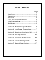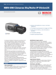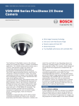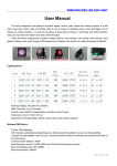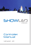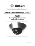
1
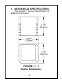
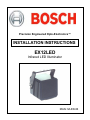
Precision Engineered Opto-Electronics™ INSTALLATION INSTRUCTIONS EX12LED Infrared LED Illuminator MAN-12LED-06 IMPORTANT SAFETY INSTRUCTIONS 1. Read these instructions. 2. Keep this instruction. 3. Heed all warnings. 4. Follow these instructions. 5. Do not use this apparatus near water. 6. Clean only with dry cloth. 7. Install in accordance with manufacturer instructions. 8. Do not install near any heat sources over manufacture specification temperature. 9. Only use attachments/accessories specified by the manufacturer. 10. Refer all servicing to qualified service personnel. Servicing is required when the apparatus has been damaged in a way, such as the apparatus has been exposed to rain or moisture, does not operate normally, or has been dropped. IMPORTANT For best results, please read this Instruction Booklet prior to installing the EX12LED Illuminator Unit. WARNING! CSA Certified / UL Listed CLASS 2 power adaptors must be used in order to comply with electrical safety standards. EU Directives covered by this declaration: 72/9/EC Low Voltage Directives 89/336/EEC Electromagnetic Compatibility Directive This installation should be made by a qualified service person and conform to all local codes. EXTREME CCTV™ will not be responsible for injuries or damages resulting from the improper installation or use of any product sold by EXTREME CCTV™, their agents, distributors or dealers. NOTE: This equipment has been tested and found to comply with the limits for a digital device, pursuant to part 15 of the FCC rules. These limits are designed to provide reasonable protection against harmful interference in a residential installation. As part of its’ normal operation this device can generate radio frequency energy and if not installed and used in accordance with the installation manual may cause interference to radio communications. However, there is no guarantee that interference will not occur on a particular installation. If the device does cause interference to radio or television reception the user is encouraged to try to correct the interference by one or more of the following measures: 1) Fit Ferrite beads on all cable to and from the power supply box, within the box walls. 2) Route the composite cable between the camera and the power supply in steel conduit piping over the entire run of the cable up to and including connection to a deep conduit base fitted under the camera and a conduit fitting adaptor in the wall of the PSU box. 3) Contact BOSCH Service Center for further advice. INDEX – EX12LED Page Description.................................................. 1 Unpacking................................................... 2 Parts List..................................................... 2 Items Required for Installation .................... 2 Initial Preparations ...................................... 3 Guidelines................................................... 3 Section 1. Mechanical Specifications.......... 4 Section 2. Input Power Connections ........... 7 Section 3. Mounting – Illuminator Unit ........ 8 Section 4. LED Adjustments ..................... 11 Section 5. Illuminator Re-Assembly .......... 13 Section 6. Troubleshooting Guide............. 15 Section 7. General Specifications ............. 17 DESCRIPTION The EX12LED Infrared LED Illuminator provides night-time covert lighting for short range indoor and outdoor surveillance when used in conjunction with existing or newly installed monochrome cameras. Its compact cube shape is comprised of 42 LEDs mounted into a solid core CNC machined aluminum housing and beamed through a dark-tinted tough window. The EX12LED has an effective range up to 40 feet and is available in 850nm or 940nm with 30º or 60º beam spread. A voltage regulator circuit allows for 12-24ac/dc a range operation; also providing protection from voltage surge, transient spikes, and reverse voltage. The EX12LED is available in several models designed to meet specific needs. See the Light. Get the Picture. ™ 1 UNPACKING Care should be taken when unpacking the shipped unit. Check the parts list and confirm all items have been located. Inspect the equipment thoroughly to ensure nothing was damaged in transit. Contact BOSCH Service Center if a problem is noted, see the rear page of this booklet for contact numbers. PARTS LIST (items supplied with unit) - EX12LED Unit including one “U” shaped mounting bracket with fasteners - Installation Instructions booklet ITEMS REQUIRED FOR INSTALLATION (Not supplied with unit) - Philips screwdriver - Small slotted screwdriver - Mounting screws, etc. 2 INITIAL PREPARATIONS The EX12LED operates in either Vdc or Vac mode. The power input supply voltages can be 12-24VAC/DC See Section 2, Input Power Connections – Reference Only. Determine the optimum location for the Illuminator unit. See Section 3, Mounting-Illuminator Unit. All units have been tested prior to shipment, but it is advisable to check the unit’s operation before installation. GUIDELINES The installation and set-up of the EX12LED is explained in Sections 3 and 4. It is important that these steps are followed in sequence: 3 1. MECHANICAL SPECIFICATIONS (See Section 7 - General Specifications, for additional information) FIGURE 1 – 1 Outline Dimensions 4 FIGURE 1 – 2 Front View 5 FIGURE 1 – 3 Rear View 6 2. INPUT POWER CONNECTIONS – Reference Only The voltage operating range is 12~24AC/DC. Note: input leads are not polarity dependent. LED Power Input VRB Power Input FIGURE 2 - 1 Voltage Regulator Board (VRB) 7 3. MOUNTING - ILLUMINATOR UNIT Select a suitable location that is protected from accidental damage, tampering, and environmental conditions exceeding the LED’s specifications. Caution: The selected mounting location should not place the camera in a situation where its environmental specifications could be exceeded. See page 17. Ensure the selected location is protected from falling objects, accidental contact with moving objects, and unintentional interference from personnel. Follow all applicable building codes. The following installation guidelines must be followed: Locate the camera such that it cannot be easily interfered with, either intentionally or accidentally. Select a mounting surface capable of supporting the combined weight of the camera and mounting hardware under all expected conditions of vibration and temperature. 8 Secure all cabling. Installations on drywall must use a ¼” bolt and drywall butterfly type anchor or superior connection. The EX12LED can be mounted to any flat surface. The supplied “U” shaped mounting bracket allows for tilt as well as rotation. If this mounting bracket does not suit the needs of the installation, the installer can utilize either of the two ¼-20 camera-mount holes located in the housing (see Figure 1-3 on page 6). The choice of camera-type mounting brackets is left to the installer. Step 3.1 - Mount the “U” bracket to the chosen mounting surface and attach the EX12LED with the supplied adjustment screws. See Figure 3-1 on page 10. Step 3.2 - Tighten the EX12LED into its approximate viewing direction. Proceed to Section 4. 9 Note: The Tilt Adjustment screws should be loosened only. Do not remove these screws. FIGURE 3 - 1 Mounting Details 10 4. LED ADJUSTMENTS Note: The current setting of LED is 0.9A by manufacturer default. End user not advisable for adjustment. For photocell “On/Off” light-level adjustment, rotate VR2. Clockwise is off and counter-clockwise is on. Photocell On/Off Adjustment FIGURE 4 - 1 LED and Photocell Adjustments 11 5. ILLUMINATOR UNIT RE-ASSEMBLY Make sure the input power wires are properly connected and tightened into the terminal block, all holes are sealed against moisture penetration and all mounting screws are tight. Step 5.1 - Check the gasket attached to the rear cover plate has not been dislodged or warped. Step 5.2 - Gently press the rear cover into place, making sure the gasket is properly seated and the photocell is centered in its viewing window. See Figure 5-1 on page 14. Step 5.3 - Attach the rear cover to the housing. Step 5.4 - Ensure the power cable has enough slack so that it is not stressed or crimped when the EX12LED unit is fixed into its final mounting position. 12 FIGURE 5 – 1 Rear Cover Re-Assembly 13 6. TROUBLESHOOTING GUIDE PROBLEM POSSIBLE SOLUTION Fuse Blows - Check fuse rating. - Check for shorting between the enclosure and the input power. Don’t know if LEDs are “ON” 850nm LEDs will have a faint red glow when “ON”.940nm LEDs are covert. Aim the LEDs directly at an IR sensitive camera to see the lights or wait for the LEDs to warm up (two minutes). Feel for warmth. LEDs are not “ON” Cover the photo sensor to activate power to the LEDs (up to 30 seconds delay for activation). Adjust the photocell’s variable resistor towards the “ON” position. Adjust power to the LEDs. 14 PROBLEM POSSIBLE SOLUTION LEDs are not turning “OFF” when sufficient ambient light is present - Make sure the photo sensor is not covered or hidden behind any object. - Check that the photocell is recessed in the viewing window. - Adjust the photocell’s variable resistor towards the “OFF” position. The LEDs will stay “ON” or “OFF” if the adjustments are at full turn. 15 7. GENERAL SPECIFICATIONS LED Type........... High Perf. 850nm / 940nm LED Beam Angles ... 60deg. (W), 30deg. (M) Operational Range................-20°C to +50°C ( -4°F to 122°F ) Humidity Range .............Up to 85% (relative) Power Supply ....................12V dc or 24V ac (60Hz), 9W Viewing Window ................................ Acrylic Housing ............................... CNC Aluminum Anodized Dimensions................... W: 2.875” (73.0mm) H: 2.750” (69.9mm) D: 2.750” (69.9mm) Weight ................................. 1.0 lbs. ( 454g ) Subject To Change Without Notice 16 Americas Bosch Security Systems, Inc. 850 Greenfield Road Lancaster, Pennsylvania 17601 USA Telephone+ 1 888-289-0096 Fax + 1 585-223-9180 Email: [email protected] www.boschsecurity .us Europe, Middle East, Africa: Bosch Security Systems B.V. P.O. Box 80002 5600 JB Eindhoven, Netherlands Phone: + 31 40 2577 284 Fax: + 31 40 2577 330 [email protected] www.boschsecurity.com Asia Pacific: Bosch Security Systems Pte Ltd. 38C Japan Pemimpin Singapore 577 180 Phone: +65 6319 3450 Fax: +65 6319 3499 [email protected] www.boschsecurity.com © Bosch Security Systems., Inc. 2009; Data subject to change with out notice 17