1
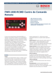
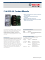
Fire Alarm Systems | FLM‑325‑IM Contact Module
FLM‑325‑IM Contact Module
▶ Digital data communications and power provided over
a two-wire circuit
▶ Advanced digital communications protocol
compatible
▶ Class B circuit for dry contact devices
▶ Module address programming (1-254) with the D5070
Analog Device Programmer
The FLM‑325‑IM Contact Module provides a variety of fire
alarm functions, such as monitoring manual pull stations,
waterflow devices, or other dry contact fire alarm
activation applications. The module allows for alarm,
trouble, and supervisory conditions. The module is
mounted inside of a single‑gang back box and is normally
out of view.
Certifications and Approvals
Region
Certification
USA
UL
UOXX: Control Unit Accessories, System
(ANSI/UL 864)
Installation/Configuration Notes
System Overview
The FLM‑325‑IM Contact Module allows compatible fire
alarm control panels (FACP) to supervise Form A or B dry
contact devices in a polling circuit. The module has an
eight‑bit microprocessor and communicates with the
control panel (both power and data) over a two-wire
polling circuit. The initiating device circuit (NFPA Style B)
connected to the module can have up to 20 normally-open
(NO) dry contact devices. Each module can monitor one
normally-closed (NC) device (NC devices must be nonalarm applications).
The following products are compatible with the
FLM‑325‑IM Contact Module:
Category
Product ID
Product Description
Control Panels:
FPA‑1000
Series
Analog addressable fire panels
Pull Stations
FMM‑325A
Analog addressable manual pull
station (single action)
FMM‑325A‑D
Analog addressable manual pull
station (double action)
D5070
Analog device programmer
Programmers:
www.boschsecurity.com
2 | FLM‑325‑IM Contact Module
Data Circuit Length
Mechanical
Data (or polling) circuit length is the distance over the
circuit wire from the connection at the FACP to the most
distant device and back to the FACP. Data circuit length
must include the distance to any device connected to the
circuit in a T tap. The screw terminals can accept up to 14
AWG (1.5 mm) wire, but this reduces the allowable length
of the circuit.
Refer to the FPE‑1000‑SLC Installation Guide
(P/N: F01U078099) for specific wire instructions and
specifications for the FPA‑1000 series panels.
Initiating Device Circuit Connections
The initiating device circuit can use any number of ULlisted normally open (NO) contact closure devices. Device
circuit wiring must not exceed 50 Ω. Install contact
closure devices according to the manufacturer’s
installation instructions. All wiring must be supervised and
power-limited.
Note
Do not mix fire alarm initiating and
supervisory devices on the same module.
Dimensions (H x W x D)
2.375 in. x 1.75 in. x 0.5 in.
(60.325 mm x 44.45 mm x 12.7 mm)
Weight
20 oz (0.567 kg)
Trademarks
Trademark names are used throughout this document. In
most cases, these designations are claimed as trademarks
or registered trademarks in one or more countries by their
respective owners. Rather than placing a trademark
symbol in every occurrence of a trademark name, Bosch
Security Systems, Inc. uses the names only in an editorial
fashion and to the benefit of the trademark owner with no
intention of infringing the trademark.
Hochiki is a trademark of Hochiki America Corporation.
Ordering Information
FLM‑325‑IM Contact Module
Allows compatible fire alarm control panels
(FACP) to supervise Form A or B dry contact
devices in a polling circuit
Parts Included
Quant.
Component
1
Point contact module
1
EOL resistor: Hochiki P/N 0400‑01046,. 10 kΩ, ¼ W, ¼ in.
1
Literature – Installation Guide
Technical Specifications
Electrical
SLC Applied Voltage (rated range):
25.3 VDC to 39 VDC
SLC Current Consumption:
Standby: 0.339 mA
Alarm: 0.358 mA
Resistance
End of Line Device
10 kΩ, 0.25 W per resistor
Initiating Device Circuit
Less than 50 Ω
Environmental
Environment:
Indoor dry
Relative Humidity:
Up to 90%, non‑condensing
Temperature:
Operating: 0°C to +49°C (+32°F to +120°F)
Storage: -30°C to +70°C (-22°F to +158°F)
Americas:
Bosch Security Systems, Inc.
130 Perinton Parkway
Fairport, New York, 14450, USA
Phone: +1 800 289 0096
Fax: +1 585 223 9180
[email protected]
www.boschsecurity.us
Europe, Middle East, Africa:
Bosch Security Systems B.V.
P.O. Box 80002
5600 JB Eindhoven, The Netherlands
Phone: + 31 40 2577 284
Fax: +31 40 2577 330
[email protected]
www.boschsecurity.com
© Bosch Security Systems 2011 | Data subject to change without notice
T7621673227 | Cur: en-US, V1, 25 May 2011
Asia-Pacific:
Represented by
Robert Bosch (SEA) Pte Ltd, Security Systems
11 Bishan Street 21
Singapore 573943
Phone: +65 6258 5511
Fax: +65 6571 2698
[email protected]
www.boschsecurity.asia
FLM-325-IM