1
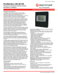
DS9400 Series
Release Notes for Firmware V2.07
EN
Fire Alarm Control Panel
DS9400 Series | Release Notes for Firmware V2.07 | Trademarks
Upgrade Information
Trademarks
If this firmware is installed in a control
panel that has been running version 1.x
software, it is necessary to erase the old
programming in the control panel and reselect the control panel type when the
control panel is first powered up. Be
careful to select “1-DS9400”- an incorrect
selection cannot be undone.
Gentex™ is a trademark of Gentex Corporation, Fire
Protection Group
CleanMe® is a registered trademark of GE
Interlogix
1.0 Fixed Items in Firmware
Version V2.07
The D9400 Series Fire Alarm Control Panel (FACP)
V2.07 fixes two bugs:
•
When the Drill button was pressed, only the
Local Notification Appliance Circuits would
activate. This has been corrected, and the
DS9484 Remote NAC supply also activates.
•
In Firmware Version V2.06, a bug was created
when silencing a multiple output module
(DS9488/B or DS9489/B), causing some outputs
not to silence. This worked correctly in other
firmware versions, but worked incorrectly when
changing the silence priority feature.
3.0 Fixed Items in Firmware
Version 2.05
Version 2.05 firmware for the DS9400 Series Fire
Alarm Control Panels (FACP) incorporates a bug fix
for auto-programming and updates the panel to
work with the DS9431 with V1.04 ROM or later.
•
2.0 Fixed Items in Firmware
Version 2.06
Version 2.06 firmware for the DS9400 Series Fire
alarm Control Panels (FACP) incorporates a change
to Preassigned Zone 61 and a bug fix for Outputs
assigned to Silencable points.
Auto-programming.
1.
When selecting a device type of I/O, the
first address programs correctly but if any
device option is selected other than “no
device,” the second address results in an
“Address Error 2.” This V2.05 ROM fixes
this issue.
2.
The Auto-program feature of the DS9400
with V2.04 ROM does not work properly if
a DS9431 V1.04 MUX driver or later is
installed. The DS9400 with V2.05 ROM is
backwards compatible with V1.04 and
earlier versions of the DS9431.
•
Preassigned Zone 61 – General Water flow
(Silencable) has been changed to a NonSilencable Zone type.
4.0 Fixed Items in Firmware
Version 2.04
•
Preassigned Zone 53 – General Fire alarm
(Silencable) has been fixed so that a NonSilencable point will take priority over a
Silencable point.
Version 2.04 firmware for the DS9400 Series Fire
Alarm Control Panels (FACP) incorporates several
new features and improvements:
2
1.
This condition may happen when both
Silencable and Non-Silencable points are
mapped to the same output.
2.
Version 2.05 and prior would configure the
output to Silencable or Non-Silencable
depending on the last event type activated.
•
Gentex™ Sync Protocol. The control panel can
now send Gentex protocol to Gentex
Notification Appliance Circuit (NAC) devices.
Gentex NAC devices can be added directly to
the NAC circuits without a sync module.
•
CleanMe®. The control panel recognizes the
Clean-Me signal from Detection System’s F220
Series Smoke Detectors. If the smoke detectors
get dirty, a signal is sent on the two-wire loop,
and the control panel will annunciates that there
is a dirty detector on the loop.
Bosch Security Systems | 8/06 | 36925V
DS9400 Series | Release Notes for Firmware V2.07 | 5.0
.
•
•
Wheelock Sync Protocol. This feature no
longer requires the Detection Systems
D411/D412 in order to produce Temporal Code
3.
Auto Silence Operation. The auto-silence
operation is now correctly processed on a
system configured to use the autosilence feature
that powers up with a trouble condition.
•
Reorganized Phone Programming Menu. To
better differentiate phone line features versus
phone number features, the phone programming
menu has been reorganized.
•
Relay Outputs. When an output is set to follow
a point, the output releases when the silence key
is pressed. This feature has been fixed and will
now stay latched for elevator recall and fan
control.
5.0 DS9400 Series Version
2.03A October, 2002
Version 2.03A firmware for the DS9400 Series Fire
Alarm Control Panels incorporates a change in the
Contact ID reports and a change in the Trouble
Relay Function as described below.
•
•
Contact ID Reporting. The system can be
programmed to send a periodic test report,
E602, in Contact ID format. If any system
troubles are present at the periodic test time, a
new event, E608, which states “New event, off
normal at time of periodic test report” is sent.
Software versions 2.03 and before sent a generic
system trouble P300 report.
General Trouble Relay Function for the
onboard relays only. In order to provide an
output that is energized when the control panel
is operating normally, the operation of the
“General Trouble" output type (Zone 62) has
been changed.
•
The change is observed when Zone "A" for one
of the two on-board relays is programmed using
Zone 62 (General Trouble). For this output, the
relay will be energized when there are no
troubles present in the system. When there is a
trouble, the relay will de-energize.
•
For this relay to function properly, Zones "B",
"C", and "D" must be programmed with a value
of "00". The General Trouble output function
can not be combined with any other output
function.
Bosch Security Systems | 8/06 | 36925V
DS9400 Series Version 2.03A October, 2002
When communicating to the control panel
using RPS, the control panel will report
v2.03 software installed even when the
upgrade v2.03A has been installed.
6.0 Fixed Items in Firmware
Version 2.03
The following list of fixed items only applies
to control panels that have version 2.03
firmware installed and a date code later
than 9935. These items may still apply to
control panels running an earlier version of
firmware, and/or have a date code of 9935
or earlier.
•
“REPROGRAM SYS” Message: With
firmware version 2.03, the System Trouble
message, “TROUBLE EEPROM” has been
changed to “REPROGRAM SYS.” This message
will appear:
•
when the control panel is powered up for the
first time with firmware version 2.03 installed
•
if there is an invalid EEPROM checksum
•
if the control panel has been defaulted
improperly and system programming has not
been performed
•
To clear the “REPROGRAM SYS” message, use
the following procedure:
•
From the Main Menu, press the 0/Prog key to
enter the Programming Menu. The
Programming Menu will appear.
•
Reprogram the system according to site-specific
information.
•
Exit the programming mode by pressing the
*/Clear key until the Main Menu reappears.
If the control panel is defaulted from the
programming mode, the “REPROGRAM SYS”
message will not appear. When this message
appears, check all programming entries from the
built-in user interface, or from a remote
connection using Bosch Security Systems’ RPS
Remote Programming Software.
3
DS9400 Series | Release Notes for Firmware V2.07 | 7.0
•
DS9431 Accidental Removal (DS9400M
only): On control panels running firmware
version 2.02 or earlier, if the wires on the
keypad option bus are momentarily shorted for
less than a second, the DS9431 Multiplex
Expansion Module may stop working. If this
occurs, the display will show “MUX NOT
DETECTED” and the Trouble buzzer will
sound. If the */Clear key is pressed, the DS9431
will be uninstalled.
Firmware version 2.03 corrects this problem. If
the DS9431 should fail, a new message, “CALL
FOR SERVICE,” will be displayed along with
the following message, “MUX NOT
WORKING.” Pressing the */Clear key will
silence the Trouble buzzer, but will neither clear
the trouble messages nor uninstall the DS9431.
If “MUX NOT WORKING, CALL FOR
SERVICE” or INST.FLT MX EXP” is
displayed, the control panel should be powered
down by removing AC and standby battery
connections, and then restarted. Doing so will
restore the DS9431 to proper operation. If the
problem is not corrected, please contact
Technical Support at (888) 886-6189.
Fixed Items Since Firmware Version 1.08
Boards shipped before August 31, 1999
must be modified according to Technical
Service Note (P/N: 42363) to ensure that
the battery test runs properly. Affected
boards carry a lot number of 99 or lower
and a date code of 9935 or earlier. Boards
shipped after August 31, 1999 with a date
code higher than 9935 are unaffected. See
Figure 1 on page 3 for the location of the
lot number and date code.
Figure 1:
Firmware Version Label and Date
Code Locations
1
3
XXXX
2
Make sure that you are at the control panel
site with an available phone line before
calling Technical Support.
To remove the DS9431 after installing firmware
version 2.03, please contact Technical Support at
(888) 886-6189.
•
DS9434 Four Point Expander Removal: To
prevent the accidental removal of the DS9434, a
new message “CALL FOR SERVICE,” is
displayed. If you wish to remove a previously
installed DS9434, please contact Technical
Support at (888) 886-6189.
7.0
•
4
Fixed Items Since
Firmware Version 1.08
1
2
3
Lot Number Label
Firmware Version Label
Date Code Stamp
Do not exceed standby current ratings for
the control panel. If the total current drawn
from the smoke power and option bus
power terminals exceeds 1 amp, the
system may not be able to switch to battery
power when AC fails. Current drawn from
NACs and auxiliary power does not impact
battery transfer operation.
AC Failure during Automatic Battery Test:
The DS9400 FACP automatically tests the
standby batteries every 180 seconds for two
seconds. The system will now continue normal
operation if an AC power failure occurs exactly
during this two-second battery test window.
Bosch Security Systems | 8/06 | 36925V
DS9400 Series | Release Notes for Firmware V2.07 | 7.0
.
•
•
Manual Battery/NAC Test during AC Fail:
Manually initiating a battery test (Test Menu,
Option 4) when AC has failed will now correctly
display the current battery voltage. However, if
a user at the control panel requests a manual
battery test within five seconds after AC power
fails, the system may shut down until AC power
returns. Manual battery test while AC is present
will correctly test and report the battery voltage,
and a manual test when AC power has failed
will report the current battery voltage.
Improved Smoke Power Control
Monitoring: When AC power fails, the control
panel draws from the batteries to maintain
operation. When the battery voltage falls below
20 volts, the control panel will shut down.
Panels with date codes after 9935 will power
down, and control panels modified according to
Technical Service Note P/N: 42363 will enter a
low power idle state. To ensure that all attached
smoke detectors are correctly powered up after a
shutdown, the control panel will wait for the
smoke power voltage to stabilize before applying
smoke power and continuing operation.
To ensure that power is applied cleanly to the
smoke detectors, smoke power is now turned off
if it falls below 15 volts and not restored until it
reaches 20 volts.
•
Improved Battery Monitoring: Processing of
restored batteries has been improved so that a
RESET operation is never required.
•
Local Only Points Implemented: Central
station reporting is now correctly suppressed for
points programmed for “Local Only” operation.
•
Response Time After Transients: Firmware
prior to version 2.02 may allow an extended
alarm response time after an electrical transient
(e.g. lightning). In the worst case, an alarm
occurring 10 minutes after a transient would
take 10 minutes to be registered. After 10
minutes, the response time returns to normal.
With version 2.02 firmware, response time
correctly remains at 500 ms for fast response, or
at the desired programmed response time for
programmed response points, regardless of
possible prior transients on the line. This issue
was observed during recent lab testing of the
control panel and has not been reported from
actual installations, but upgrading the firmware
in installed control panels to version 2.02 will
assure proper response time under all
circumstances.
Bosch Security Systems | 8/06 | 36925V
Fixed Items Since Firmware Version 1.08
•
Programming Access: Firmware version 2.02
corrects a configuration problem found in
control panels with prior firmware that
improperly allows programming access to all
valid user codes and not only “Level
1/Maximum” codes.
•
Phone Troubles: On a small number of
DS9400 units, when using firmware prior to
version 2.02, an interaction between normal
hardware variations and firmware timing has
been observed to cause the control panel to
falsely report a disconnected phone line. On the
small number of control panels with the affected
hardware, the fault causes occasional phone
trouble reports that are followed by an
immediate restoral report. Replacing the ROM
to upgrade the firmware to version 2.02 corrects
the problem with no need for hardware
modifications.
•
User Interface Delay: Under unusual
circumstances, the user interface in firmware
prior to 2.02 would stop accepting input for up
to three minutes if remote keypads were present
on a system. This no longer occurs in version
2.02.
•
Relay Module Operation, Disabling: Remote
relay modules may fail to activate properly
under some circumstances in firmware versions
prior to 2.02. Additionally, attempting to disable
remote relays has caused the control panel to
stop operating and freeze the display. The relay
modules operate and can be disabled as
expected in version 2.02. Note that when a
remote relay module is disabled, all eight relays
on the module are disabled with one operation.
•
Auto Silence Clarification: When configuring
points and NACs for auto silence, the setting on
each NAC to enable or disable the auto silence
feature is not implemented. Setting the timer to
a value other than zero (0) enables the auto
silence feature. Any NAC that can be silenced
(based on which inputs are in alarm) will be
silenced when the auto silence timer completes,
regardless of the setting selected for the
individual NACs. Additionally, a NAC activated
by a non-latching point will not automatically
turn off when the point restores if there is any
other off-normal condition on the control panel.
It must be manually reset.
5
DS9400 Series | Release Notes for Firmware V2.07 | 8.0
8.0 New Features since
Firmware Version 1.X
•
Supports the DS9431 Multiplex Expansion
Module to add addressable points (247
additional points, including input modules and
I/O modules)
•
User codes expanded to 100 with DS9431
installed
•
History log expanded to 499 events with
DS9431 installed
•
Supports remote programming
9.0 Known Issues with
Firmware Version 2.07
•
•
•
•
6
Point Disabling: It is not recommended that
the “disable all inputs” feature be used on larger
systems. Instead, disable individual points as
needed. During “disable all” operations, the
system adds or removes points to the list at a
rate of approximately 15 seconds per point. It
may take as much as an hour to log, report and
update the display list when 255 points are
processed. Additionally, this will trip the daily
trouble reporting limit for the control panel,
inhibiting other trouble reports for 24 hours.
When disabling or enabling all points, the
display appears to freeze for a few seconds while
the operation is performed.
Multiplex Point Response Time: Multiplex
point response time may increase to as much as
20 seconds when all points on the multiplex bus
are held off normal. Onboard points may have a
response time as long as 1 second when set for
0.5 second (fast) response time. Refer to the
manual for more information.
Reporting Multiple Troubles: When using
faster central station reporting formats, the
control panel may be able to report trouble
conditions faster than it can add them to a long
list of off-normal conditions. This may result in
less than the possible maximum of eight reports
being included in each phone call.
Removal of DS9431 Multiplex Expansion
Module Clears PINs: If the DS9431 Multiplex
Expansion Module is installed, and then
removed, all Personal Identification Numbers
(PINs), including the standard 16 PIN numbers,
will be erased when the DS9400 is re-powered.
The PIN numbers can be re-entered normally.
New Features since Firmware Version 1.X
•
User ID Report for Drill and Walk Test: As
shown in Appendix C of the DS9400M
Reference Guide (P/N: 31499) or the DS9400i
Reference Guide (P/N: 43707), the control panel
does not report the ID of the person starting a
fire drill or walk test to the central station.
•
Remote Programming Annunciation: To
indicate that the system is in a special operating
mode with user input inhibited (but alarm
monitoring continuing), the system indicates
“SYSTEM TROUBLE,” “RMT PRG
ACTIVE” during remote programming.
Sounders will not activate during this mode, but
other outputs programmed for Zone 62, general
system trouble, will activate.
Phone Monitor Troubleshooting
1.
Some troubleshooting tips for phone monitor
problems are listed below:
2.
Use a voltmeter to measure the voltage present
across each phone line (Tip to Ring) while the
phone line is idle.
The voltage present during ringing for an
incoming call can be over 100 VAC.
3.
4.
•
The standby Telco “battery” voltage is
typically in the range of 30-50 VDC, but
any voltage above 5 VDC will be accepted
by the control panel.
•
The polarity of the voltage does not matter.
Check for other devices that may use the phone
line, such as fax machines, credit card verifiers
or PBX systems.
•
Note that NFPA 72 requirements mandate a
dedicated phone line for fire reporting.
•
If the devices cannot be removed, make
sure they are wired so that the control
panel’s line seizure relay will disconnect
them when needed.
•
Measure the line voltage while these devices
are in use. Make sure that it remains above
5V.
Check for intermittent faults in the phone line.
•
Make a test call and see that the line is free
of distortion and noise.
Bosch Security Systems | 8/06 | 36925V
DS9400 Series | Release Notes for Firmware V2.07 | 9.0
Known Issues with Firmware Version 2.07
.
•
5.
6.
Temporarily swap lines 1 and 2 on the
control panel and see if the problem
indication moves to the control panel’s other
phone line channel, in which case the phone
line is causing the problem rather than the
line monitor.
Confirm that the fault message is “phone fault”
and not “Comm fault”.
•
“Comm fault” is often caused by failing to
program a phone number or account
number for phone number 2, while routing
reports to “line 1, backup line 2”.
•
If only one phone number is available for
reporting, set report steering for all events to
“phone 1 only”.
•
“Comm fault” may also be caused if one of
the phone lines has Telco battery voltage,
but will not complete a call. Make test calls
to the receiver(s) on both phone lines,
listening for the receiver ACK tone
Make sure that two phone lines are available.
•
In accordance with NFPA requirements, the
auto-test report is sent on a different phone
line each time it is sent. If only one phone
line is connected to the control panel, a
“Comm fault” will be generated on every
other test call.
Bosch Security Systems | 8/06 | 36925V
7
Bosch Security Systems
130 Perinton Parkway
Fairport, NY 14450-9199
Customer Service: (800) 289-0096
Technical Support: (888) 886-6189
© 2006 Bosch Security Systems
36925V