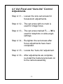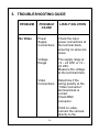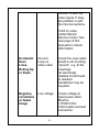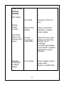
1
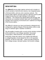
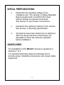
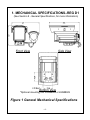
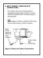
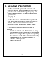
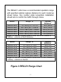
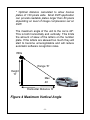
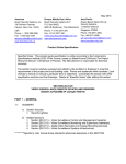
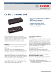
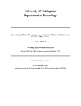
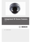
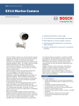
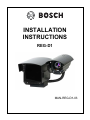
INSTALLATION
INSTRUCTIONS
REG-D1
MAN-REG-D1-03
IMPORTANT SAFETY INSTRUCTIONS
1.
Read these instructions.
2.
Keep this instruction.
3.
Heed all warnings.
4.
Follow all instructions.
5.
Do not use this apparatus near water.
6.
Clean only with dry cloth.
7.
Do not block any ventilation openings. Install in
accordance with manufacturer instructions.
8.
Do not install near any heat sources such as
radiators, heat registers, stoves or other
apparatus (including amplifiers) that produce
heat.
9.
Do not defeat the safety purpose of the polarized
or grounding-type plug. A polarized plug has two
blades with one wider than the other. A
grounding type plug has two blades and a third
grounding prong. The wide blade or the third
prong is provided for your safety. If the provided
plug does not fit into your outlet, consult an
electrician for replacement of the obsolete outlet.
10. Protect the power cord from being walked on or
pinched particularly at plugs, convenience
receptacles, and the power where they exit from
the apparatus.
11. Only use attachments/accessories specified by
the manufacturer.
12. Use only with the cart, stand, tripod, bracket, or
table specified by the manufacturer, or sold with
the apparatus. When a cart is used, use caution
when moving the cart/apparatus combination to
avoid injury from tip-over.
13. Unplug this apparatus during lightning storms or
when unused for long periods of time.
14. Refer all servicing to qualified service personnel.
Servicing is required when the apparatus has
been damaged in a way, such as power-supply
cord or plug is damaged, liquid has been spilled
or objects have fallen into the apparatus, the
apparatus has been exposed to rain or moisture,
does not operate normally, or has been dropped.
IMPORTANT
For best results, please read this Instruction Booklet prior
to installing the REG-D1 camera.
WARNING !
CSA Certified / UL Listed CLASS 2 power adaptors must
be used in order to comply with electrical safety standards.
This installation should be made by a qualified service
person and conform to all local codes.
Bosch Security Systems, Inc. will not be responsible for
injuries or damages resulting from the improper installation
or use of any camera sold by Bosch Security Systems,
Inc., their agents, distributors or dealers.
EU Directives covered by this declaration:
72/9/EC Low Voltage Directives
89/336/EEC Electromagnetic Compatibility Directive
NOTE: This equipment has been tested and found to
comply with the limits for a digital device, pursuant to part
15 of the FCC rules. These limits are designed to provide
reasonable protection against harmful interference in a
residential installation. As part of its normal operation this
device can generate radio frequency energy and if not
installed and used in accordance with the installation
manual may cause interference to radio communications.
However, there is no guarantee that interference will not
occur on a particular installation. If the device does cause
interference to radio or television reception the user is
encouraged to try to correct the interference by one or
more of the following measures:
1) Fit Ferrite beads on all cable to and from the power
supply box, within the box walls.
2) Route the composite cable between the camera and the
power supply in steel conduit piping over the entire run of
the cable up to and including connection to a deep conduit
base fitted under the camera and a conduit fitting adaptor
in the wall of the PSU box.
3)Contact Bosch Service Center for further advice.
INDEX – REG - D1 Camera
Description………………………………………………...1
Unpacking………………………………………………....2
Parts List…………………………………………………..2
Items Required for Installation…………………………..2
Initial Preparations………………………………………..3
Guidelines………………………………………………....3
1.
2.
3.
4.
5.
6.
Mechanical Specification REG-D1………………....4
Input Power / Video Output Connections………….5
Mounting Specification………..……………………..6
Color Overview Camera Lens Setting…………… 10
Troubleshooting…………...…………………… …..14
General specifications…………..……………… … 18
DESCRIPTION
The REG-D1 license plate capture camera unit consists of
one IR-sensitive monochrome camera, one integrated panel
of Infrared LEDs, and one color overview camera. The
license plate capture camera produces optimum license plate
images during day and night settings in all-weather
conditions. The camera has optical filtering technology that
help block out unwanted ambient light such as headlamps or
sunlight, thus ensuring no bloomed-out or washed-out images
of the license plates.
The REG-D1 camera you have purchased is designed and
configured to capture images of license plates under a wide
range of ambient light to weather conditions.
The all-weather housing with a covert acrylic window contains
all the electronics. Low voltage operation, low power
consumption, LED illuminator, and solid-state CCD
technology make this camera very reliable and efficient.
A voltage regulator circuit allows for DC or AC operation
between 12 and 24 VAC/VDC. It also provides protection
from voltage surges, transient spikes, and reverse voltage.
-1-
UNPACKING
Care should be taken when unpacking the shipped unit.
Check the parts list and confirm all items have been
located. Inspect the equipment thoroughly to ensure
nothing was damaged in transit.
Contact Bosch Service Center if a problem is noted,
see the rear page of this booklet for contact numbers.
PARTS LIST (items supplied with unit)
-
REG-D1 camera assembly
Installation Instructions booklet
One 3mm Allen key
ITEMS REQUIRED FOR INSTALLATION (not
supplied with units)
•
•
•
Mounting hardware
Mounting tools
Proper Power Supply
-2-
INITIAL PREPARATIONS
•
Determine the operating voltage at the
installation site. The camera‘s Voltage Regulator
Board accepts both 12-24VDC/VAC input
without change to internal connections.
See Section 2, Input Power Connections.
•
Determine the optimum location for the camera.
See Section 3, Mounting Specification.
•
All cameras have been tested prior to shipment.
After the wiring has been reconnected, it is
advisable to check the camera’s operation
before installation.
GUIDELINES
The installation of the REG-D1 camera is explained in
Sections 1 to 3.
It is important that these steps are followed and to
practice proper installation procedures with proper safety
equipment.
-3-
1. MECHANICAL SPECIFICATIONS–REG D1
(See Section 6 - General Specifications, for more information)
Front View
Side View
Bottom View
*Optional mounting kits: EXMB028 or EXMB029
Figure 1 General Mechanical Specifications
-4-
2. INPUT POWER / VIDEO OUTPUT
CONNECTIONS
The camera unit is pre-connected with a
electrically isolated power board for 12 to 24
VDC/VAC operation with no wiring change or
wiring polarity.
Note:
Input voltage is 12VDC to 24VDC for DC input.
The AC input range is 12VAC to 24VAC.
Input
Power
Leads for
REG and
Color
Camera
Output Video
BNC
Connectors
Figure 2 Power and Video Connections
-5-
3. MOUNTING SPECIFICATION
Caution: Install with appropriate screws to suit
mounting surface. Select a suitable location that is
protected from accidental damage, tampering and
environmental conditions exceeding the camera’s
specifications.
See page 20.
Caution: Ensure the selected location is protected
from falling objects, accidental contact with moving
objects, and unintentional interference from
personnel. Follow all applicable building codes.
&The following installation guidelines must be
followed:
•
Locate the camera such that it cannot be easily
interfered with, either intentionally or accidentally.
•
Select a mounting surface capable of supporting
the combined weight of the camera and mounting
hardware under all expected conditions of
vibration and temperature.
•
Secure all cabling.
-6-
The REG-D1 units have a recommended operation range
with specified optimal capture distance for each model as
shown below. Any number plate recognition installation
should aim to control the traffic through a lane.
Model
Range, ‘R’
Optimal
Distance*
REG-D1-816
12 – 22 ft | 3.7 – 6.7 m
16 ft | 4.9 m
REG-D1-825
20 – 34 ft | 6.1 – 10.4 m
25 ft | 7.6 m
REG-D1-835
27 ft – 48 ft | 8.2 – 14.6 m
35 ft | 10.7 m
REG-D1-850
40 ft – 68 ft | 12.2 – 20.7 m
50 ft | 15.2 m
REG-D1-875
55 ft – 80 ft | 16.8 – 24.4 m
75 ft | 22.9 m
ranges for use with number plates of size 12in x 6in (305mm x
152mm) – common in North America.
Model
Range, ‘R’
Optimal
Distance*
REG-D1-812
10 – 20 ft | 3 – 6 m
16 ft | 5 m
REG-D1-816
16 – 26 ft | 5 – 8 m
23 ft | 7 m
REG-D1-825
23 – 40 ft | 7 – 12 m
33 ft |10 m
REG-D1-835
34 – 60 ft | 11 – 18 m
50 ft | 15 m
REG-D1-850
56 – 82 ft | 17 – 25 m
72 ft | 22 m
REG-D1-875
72 – 100 ft | 22 – 30 m
92 ft | 28 m
ranges for use with number plates of size 20.6in x 4.4in (524mm x
112mm) – common in the UK.
Figure 3 REG-D1 Range Chart
-7-
* Optimal distance calculated to allow license
plates of 120 pixels wide. Most DVR application
can provide readable plates larger than 80 pixels
depending on level of image compression set on
DVR.
The maximum angle of the unit to the car is 40º.
This is both horizontally and vertically. This limits
the amount of skew of the letters on the number
plate. If the letters are skewed too much they will
start to become unrecognizable and will reduce
automatic software recognition rates.
REG
Range ‘R’
Height
‘H’
Max
40ْ
Horizontal Distance ‘D’
Figure 4 Maximum Vertical Angle
-8-
Max
40ْ
Range ‘R’
Figure 5 Maximum Horizontal Angle
If the maximum range is exceeded the letters will
become smaller and be more difficult to read. At the
max range the width of the number plate covers
approximately 12% of the width of the screen.
Note: The ‘R’, Range is the distance from the
camera to the license plate. Working below max
range gives larger number plates and hence
more accurate recognition but less lane area to
be covered. If too close the license plate could
disappear from the Field-of-View, especially for
side-mounted plates.
-9-
4. COLOR OVERVIEW CAMERA LENS
SETTING
The following steps show the installer how to
access the camera board and the camera lens.
Step 4.1 -
Remove sunshield by loosening top
bolt with a standard Philips
screwdriver.
Step 4.2 -
Disconnect the power source to the
camera and the video signal at the
BNC connector.
Step 4.3 -
Remove the four cap screws with a
3mm Allen key. See Figure 4-1 on
page 11.
Step 4.4 -
Carefully slide out the rear housing
from the main enclosure. Make sure
the gasket remains with the rear
section.
See Figure 4-2 on page 12.
Step 4.6 -
Carefully slide the rear section into
the main enclosure and tighten the
cap screws.
- 10 -
Figure 6 Rear Housing Removal
- 11 -
Remove
Cap screw
Loosen lens
set screws
Lens
Figure 7 Housing Separation for Camera,
Lens and Voltage Regulator Board
Access
- 12 -
4.1 Vari-Focal and “Auto-Iris” Control
Adjustments
Step 4.1.1 - Loosen the lens set screws for
focus/zoom adjustments.
Step 4.1.2 - The set screw with no mark is
used for image focus.
Step 4.1.3 - The set screw marked T←→ W is
used for telephoto or wide-angle
settings.
Step 4.1.4 - Re-tighten the set screws after
focus adjustments have been
completed.
Step 4.1.5 - Locate the “Auto-Iris” adjustment.
Step 4.1.6 - After adjustments are complete,
re-install the Camera lens back on
to the camera assembly
- 13 -
5. TROUBLESHOOTING GUIDE
PROBLEM
No Video
POSSIBLE
CAUSE
LIKELY SOLUTION
Power
Supply
Connections
Check the input
power connections at
the terminal block,
ensuring no wires are
loose.
Voltage
Range
The supply range is:
12 – 24 VDC or 12 –
24 VAC.
Measure the voltage
at the terminal block.
Video
Connections
Determine if the
wiring polarity at the
“Video Connector”
terminal block is
correct.
Check BNC
connector.
If still no video,
connect the camera
directly to the
- 14 -
monitor. Check the
video signal. If okay,
the problem is with
the interconnections.
If still no video,
contact Bosch
Service Center. See
rear page of this
manual for contact
information.
Horizontal
Scan
Lines,
Rolling Up
or Down
Ground
Loop on
video cable
Check the coax cable
shield is not touching
“ground”, e.g. at the
couplings.
An electrically
isolated circuit board
or isolation
transformer may be
required.
Negative,
scrambled,
or faded
image
Low voltage
Check voltage at
input power cable.
Must be
>12VDC/VAC.
Video leads reversed
connection.
- 15 -
Poor Color
Picture
Quality
Dim Image
Iris closed
Increase iris level on
lens
Snowy
Image
(cont’d.)
Noisy Power
Supply
Check connections.
Relocate or replace
power supply.
Horizontal
Scan Lines,
Rolling Up or
Down
Ground
Looping on
video cable
Check the coax cable
shield is not touching
ground, e.g. at
couplings.
An electrically isolated
circuit board or isolation
transformer may be
required.
Low voltage
Check voltage at input
power cable.
Must be >12VDC/VAC.
Negative,
scrambled,
or faded
image
- 16 -
Safety and Precaution
“Prolonged direct viewing of the REG-D1 camera product
at any distance does not pose a hazard to the retina or
cornea.”
When mounting and installing the REG-D1 camera, make
sure proper safety equipment and procedures are used
and practiced. This is to ensure the camera installation
will not potentially cause any harm to people around the
area and also the installer will be safe while performing the
installation.
Only qualified personnel shall install any Bosch Security
Systems, Inc. product. Bosch Security Systems, Inc. will
not be responsible for injuries or damages resulting from
the improper installation or use of any product sold by
Bosch Security Systems, Inc., their agents, distributors or
dealers.
- 17 -
6. GENERAL SPECIFICATIONS
Power Consumption:
27W Max.
Input Voltage:
12 – 24 VDC or
12 – 24 VAC
Enclosure (housing):
Viewing Windows:
Aluminum casting and
extrusion (sealed to
IP66 / NEMA4)
Polycarbonate and Acrylic
Dimensions:
167mm H ( 6.57” )
277mm W ( 10.9” )
306mm L ( 12.0” )
Operational Temperatures:
-500 C to +500C
Weight:
3.6kg (8.0 lbs.)
Subject to change without notice.
- 18 -
Note:
- 19 -
Note:
- 20 -
Note:
- 21 -
Americas
Bosch Security Systems, Inc.
130 Perinton Parkway
Fairport, New York, 1450, USA
Phone: + 1 800 289 0096
Fax: + 1 585 223 9180
[email protected]
www.boschsecurity.us
Europre, Middle East, Africa
Bosch Security Systems B.V.
P.O. Box 80002
5600 JB Eindhoven, The Netherlands
Phone: + 31 40 2577 284
Fax: +31 40 2577 330
[email protected]
www.boschsecurity.com]
Asia-Pacific
Bosch Security Systems Pte Ltd
11 Bishan Street 21
Singapore 573943
Phone: +65 6258 5511
Fax: +65 6258 4671
[email protected]
www.boschsecurity.com