1
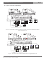
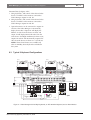
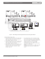
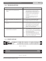
LTC 2605/91
Instruction Manual
EN Video Manager
Video Manager | Instruction Manual | Important Safeguards
EN | 2
Important Safeguards
1. Read, Follow, and Retain Instructions - All safety
and operating instructions should be read and
followed before operating the unit. Retain instructions
for future reference.
2. Heed Warnings - Adhere to all warnings on the unit
and in the operating instructions.
3. Attachments - Attachments not recommended by
the product manufacturer should not be used, as they
may cause hazards.
4. Installation Cautions - Do not place this unit on an
unstable stand, tripod, bracket, or mount. The unit
may fall, causing serious injury to a person and
serious damage to the unit. Use only manufacturerrecommended accessories, or those sold with the
product. Mount the unit per the manufacturer's
instructions. Appliance and cart combination should
be moved with care. Quick stops, excessive force, or
uneven surfaces may cause the appliance and cart
combination to overturn.
5. Cleaning - Unplug the unit from the outlet before
cleaning. Follow any instructions provided with the
unit. Generally, using a damp cloth for cleaning is
sufficient. Do not use liquid cleaners or aerosol
cleaners.
6. Servicing - Do not attempt to service this unit
yourself. Opening or removing covers may expose
you to dangerous voltage or other hazards. Refer all
servicing to qualified service personnel.
7. Damage Requiring Service - Unplug the unit from
the main AC power source and refer servicing to
qualified service personnel under the following
conditions:
• When the power supply cord or plug is damaged.
• If liquid has been spilled or an object has fallen
into the unit.
• If the unit has been exposed to water and/or
inclement weather (rain, snow, etc.).
• If the unit does not operate normally, when
following the operating instructions. Adjust only
those controls specified in the operating
instructions. Improper adjustment of other controls
may result in damage, and require extensive work
by a qualified technician to restore the unit to
normal operation.
• If the unit has been dropped or the cabinet
damaged.
• If the unit exhibits a distinct change in
performance, this indicates that service is needed.
8. Replacement Parts - When replacement parts are
required, the service technician should use
replacement parts specified by the manufacturer or
that have the same characteristics as the original part.
Unauthorized substitutions may result in fire,
electrical shock or other hazards.
9. Safety Check - Upon completion of servicing or
repairs to the unit, ask the service technician to
perform safety checks to ensure proper operating
condition.
Bosch Security Systems | December 5, 2005
10. Power Sources - Operate the unit only from the type
of power source indicated on the label. If unsure of
the type of power supply to use, contact your dealer
or local power company.
• For units intended to operate from battery power,
refer to the operating instructions.
• For units intended to operate with External Power
Supplies, use only the recommended approved
power supplies.
• For units intended to operate with a limited power
source, this power source must comply with
EN60950. Substitutions may damage the unit or
cause fire or shock.
• For units intended to operate at 24VAC, normal
input voltage is 24VAC. Voltage applied to the
unit's power input should not exceed 30VAC.
User-supplied wiring, from the 24VAC supply to
unit, must be in compliance with electrical codes
(Class 2 power levels). Do not ground the 24VAC
supply at the terminals or at the unit's power
supply terminals.
11. Coax Grounding - If an outside cable system is
connected to the unit, ensure that the cable system is
grounded. U.S.A. models only - Section 810 of the
National Electrical Code, ANSI/NFPA No.70,
provides information regarding proper grounding of
the mount and supporting structure, grounding of the
coax to a discharge unit, size of grounding
conductors, location of discharge unit, connection to
grounding electrodes, and requirements for the
grounding electrode.
12.Grounding - This unit may be equipped with a 3-wire
grounding plug (a plug with a third pin, for grounding).
This safety feature allows the plug to fit into a
grounding power outlet only. If unable to insert the
plug into the outlet, contact an electrician to arrange
replacement of the obsolete outlet. Do not defeat the
safety purpose of the grounding plug.
• Outdoor equipment should only be connected to
the unit's inputs after this unit has had its
grounding plug connected to a grounded outlet or
its ground terminal properly connected to a ground
source.
• The unit's input connectors must be disconnected
from outdoor equipment before disconnecting the
grounding plug or grounding terminal.
• Proper safety precautions such as grounding should
be followed for any outdoor device connected to
this unit.
13. Lightning - For added protection during a lightning
storm, or when this unit is left unattended and
unused for long periods of time, unplug the unit from
the wall outlet and disconnect the cable system. This
will prevent damage to the unit due to lightning and
power line surges.
EN | 3
Video Manager | Instruction Manual | Safety Precautions
For Indoor Product
1. Water and Moisture - Do not use this unit near
water - for example, in a wet basement, in an
unprotected outdoor installation or in any area
classified as a wet location.
2. Object and Liquid Entry - Never push objects of
any kind into this unit through openings, as they
might touch dangerous voltage points or create
short circuits, resulting in a fire or electrical
shock. Never spill liquid of any kind on the unit.
3. Power Cord and Power Cord Protection - For
units intended to operate with 230VAC, 50Hz,
the input and output power cord must comply
with the latest versions of IEC Publication 227 or
IEC Publication 245.
Power supply cords should be routed so they are
not likely to be walked on or pinched. Pay
particular attention to location of cords and plugs,
convenience receptacles, and the point of exit
from the appliance.
4. Overloading - Do not overload outlets and
extension cords; this can result in a risk of fire or
electrical shock.
For Outdoor Product
Power Lines - An outdoor system should not be
located in the vicinity of overhead power lines,
electric lights or power circuits, or where it may
contact such power lines or circuits. When
installing an outdoor system, extreme care should
be taken to keep from touching power lines or
circuits, as this contact might be fatal. U.S.A.
models only - refer to the National Electrical
Code Article 820 regarding installation of CATV
systems.
For Rack-mount Product
1. Ventilation - Do not place this equipment in a
built-in installation or rack, unless proper
ventilation is provided, or the manufacturer's
instructions were followed. The equipment must
not exceed its maximum operating temperature
requirements.
2. Mechanical Loading - When rack-mounting the
equipment, ensure that a hazardous condition is
not created by uneven mechanical loading.
Bosch Security Systems | December 5, 2005
Safety Precautions
CAUTION: TO REDUCE THE RISK OF
ELECTRIC SHOCK, DO NOT REMOVE COVER
(OR BACK). NO USER SERVICEABLE PARTS
INSIDE. REFER SERVICING TO QUALIFIED
SERVICE PERSONNEL.
This symbol indicates the presence of
uninsulated “dangerous voltage” within the
product’s enclosure that can cause an electric
shock.
This symbol indicates the presence of
important operating and maintenance
(servicing) instructions in the literature
accompanying the appliance.
Installation should be performed by qualified
service personnel only in accordance with the
National Electrical Code or applicable local
codes.
Power Disconnect. Units with or without
ON-OFF switches have power supplied to the
unit whenever the power cord is inserted into the
power source; however, the unit is operational
only when the ON-OFF switch is in the ON
position. The power cord is the main power
disconnect for all units.
EN | 4
Video Manager | Instruction Manual | FCC & ICES Information
FCC & ICES INFORMATION
Sicherheitshinweise
(U.S.A. and Canadian Models Only)
This device complies with part 15 of the FCC Rules. Operation is
subject to the following two conditions:
(1)
This device may not cause harmful interference, and
(2)
This device must accept any interference received,
including interference that may cause undesired
operation.
NOTE: This equipment has been tested and found to comply
with the limits for a Class B digital device, pursuant to Part 15 of
the FCC Rules and ICES-003 of Industry Canada. These limits
are designed to provide reasonable protection against harmful
interference when the equipment is operated in a residential
installation. This equipment generates, uses and can radiate radio
frequency energy, and if not installed and used in accordance
with the instructions, may cause harmful interference to radio
communications. However, there is no guarantee that interference
will not occur in a particular installation. If this equipment does
cause harmful interference to radio or television reception, which
can be determined by turning the equipment off and on, the user
is encouraged to try to correct the interference by one or
more of the following measures:
• Reorient or relocate the receiving antenna.
• Increase the separation between the equipment and receiver.
• Connect the equipment into an outlet on a circuit different
from that to which the receiver is connected.
• Consult the dealer, or an experienced radio/TV technician for
help.
Intentional or unintentional changes or modifications, not
expressly approved by the party responsible for compliance, shall
not be made. Any such changes or modifications could void the
user’s authority to operate the equipment.The user may find the
following booklet, prepared by the Federal Communications
Commission, helpful: How to Identify and Resolve Radio-TV
Interference Problems. This booklet is available from the U.S.
Government Printing Office, Washington, DC 20402,
Stock No. 004-000-00345-4.
VORSICHT: UM EINEN ELEKTRISCHEN SCHLAG ZU
VERMEIDEN, IST DIE ABDECKUNG (ODER RÜCKSEITE) NICHT
ZU ENTFERNEN. ES BEFINDEN SICH KEINE TEILE IN DIESEM
BEREICH, DIE VOM BENUTZER GEWARTET WERDEN
KÖNNEN. LASSEN SIE WARTUNGSARBEITEN NUR VON
QUALIFIZIERTEM WARTUNGSPERSONAL AUSFÜHREN.
Das Symbol macht auf nicht isolierte „gefährliche Spannung"
im Gehäuse aufmerksam. Dies kann zu einem elektrischen
Schlag führen.
Der Benutzer sollte sich ausführlich über Anweisungen für
die Bedienung und Instandhaltung (Wartung) in den
begleitenden Unterlagen informieren.
Achtung! Die Installation sollte nur von qualifiziertem
Kundendienstpersonal gemäß jeweils zutreffender
Elektrovorschriften ausgeführt werden.
Unterbrechung des Netzanschlusses. Geräte mit oder ohne
Netzschalter haben Spannung am Gerät anliegen, sobald der
Netzstecker in die Steckdose gesteckt wird. Das Gerät ist jedoch
nur betriebsbereit, wenn der Netzschalter (EIN/AUS) auf EIN
steht. Wenn das Netzkabel aus der Steckdose gezogen wird, ist
die Spannungszuführung zum Gerät vollkommen unterbrochen.
Precauciones de Seguridad
Sécurité
ATTENTION : POUR ÉVITER TOUT RISQUE D'ÉLECTROCUTION,
N'ESSAYEZ PAS DE RETIRER LE CAPOT (OU LE PANNEAU
PRECAUCIÓN: PARA DISMINUIR EL RIESGO DE DESCARGA
ELÉCTRICA, NO RETIRE LA CUBIERTA (NI LA PARTE
POSTERIOR). NO EXISTEN PIEZAS DE RECAMBIO EN EL
INTERIOR DEL EQUIPO. EL PERSONAL DE SERVICIO
CUALIFICADO SE ENCARGA DE REALIZAR LAS
REPARACIONES.
ARRIÈRE). CET APPAREIL NE CONTIENT AUCUN COMPOSANT
SUSCEPTIBLE D'ÊTRE RÉPARÉ PAR L'UTILISATEUR. CONFIEZ
LA RÉPARATION DE L'APPAREIL À DU PERSONNEL QUALIFIÉ.
Ce symbole signale que le produit renferme une « tension
potentiellement dangereuse » non isolée susceptible de
provoquer une électrocution.
Ce symbole invite l'utilisateur à consulter les instructions
d'utilisation et d'entretien (dépannage) reprises dans la
documentation qui accompagne l'appareil.
Attention : l'installation doit exclusivement être réalisée par du
personnel qualifié, conformément au code national d'électricité
américain (NEC) ou au code d'électricité local en vigueur.
Coupure de l'alimentation. Qu'ils soient pourvus ou non d'un
commutateur ON/OFF, tous les appareils reçoivent de l'énergie une
fois le cordon branché sur la source d'alimentation. Toutefois,
l'appareil ne fonctionne réellement que lorsque
le commutateur est réglé sur ON. Le débranchement du cordon
d'alimentation permet de couper l'alimentation des appareils.
Bosch Security Systems | December 5, 2005
Este símbolo indica que existen puntos de tensión peligrosos
sin aislamiento dentro de la cubierta de la unidad. Estos
puntos pueden constituir un riesgo de descarga eléctrica.
El usuario debe consultar las instrucciones de funcionamiento y
mantenimiento (reparación) en la documentación que se
suministra con el aparato.
Atención: la instalación la debe realizar únicamente personal
cualificado de conformidad con el National Electric Code o las
normas aplicables en su país.
Desconexión de la alimentación. Las unidades con o sin
interruptores de encendido/apagado reciben alimentación
eléctrica siempre que el cable de alimentación esté conectado a
la fuente de alimentación. Sin embargo, la unidad sólo funciona
cuando el interruptor está en la posición de encendido. El cable
de alimentación es la principal fuente de desconexión de todas
las unidades.
EN | 5
Video Manager | Instruction Manual | Safety Precautions
Veiligheidsmaatregelen
VOORZICHTIG: OPEN DE BEHUIZING OF DE ACHTERKANT
VAN HET APPARAAT NIET. ZO VERMINDERT U HET RISICO
OP ELEKTRISCHE SCHOKKEN. IN HET APPARAAT
BEVINDEN ZICH GEEN ONDERDELEN DIE U ZELF KUNT
REPAREREN. LAAT SERVICE EN ONDERHOUD UITVOEREN
DOOR GEKWALIFICEERD PERSONEEL.
Medidas de Segurança
CUIDADO: PARA REDUZIR O RISCO DE CHOQUE
ELÉCTRICO, NÃO RETIRE A TAMPA (OU A PARTE
POSTERIOR). NO INTERIOR, NÃO EXISTEM PEÇAS QUE
POSSAM SER REPARADAS PELO UTILIZADOR. REMETA A
ASSISTÊNCIA PARA OS TÉCNICOS QUALIFICADOS.
Dit symbool geeft aan dat er binnen in het apparaat
ongeïsoleerde, gevaarlijke spanning aanwezig is die mogelijk
elektrische schokken kan veroorzaken.
Este símbolo indica a presença de "tensão perigosa" não isolada
dentro da estrutura do produto, o que pode constituir risco de
choque eléctrico.
De gebruiker dient de bedienings- en onderhoudsvoorschriften
te raadplegen in de documentatie die werd meegeleverd met
het apparaat.
O utilizador deve consultar as instruções de funcionamento
e manutenção (assistência) nos documentos que
acompanham o aparelho.
Attentie: het apparaat mag alleen door gekwalificeerd personeel
worden geïnstalleerd. De installatie dient in overeenstemming
met de nationale elektrische richtlijnen of de van toepassing
zijnde lokale richtlijnen te worden uitgevoerd.
Spanning uitschakelen. Apparatuur met of zonder
aan-uitschakelaar staat onder spanning zolang de stekker is
aangesloten op de wandcontactdoos. De apparatuur is uitsluitend
in werking als de aan-uitschakelaar aan staat. Het netsnoer is de
"hoofdschakelaar" voor alle apparatuur.
Sicurezza
ATTENZIONE: PER RIDURRE IL RISCHIO DI SCOSSE
ELETTRICHE NON RIMUOVERE LA COPERTURA (O IL
PANNELLO POSTERIORE). L'UNITÀ NON CONTIENE
COMPONENTI INTERNI RIPARABILI DALL'UTENTE. PER
QUALSIASI INTERVENTO, RIVOLGERSI A PERSONALE
TECNICO QUALIFICATO.
Questo simbolo indica la presenza di "tensione pericolosa" non
isolata all'interno del contenitore del prodotto. Ciò comporta un
potenziale rischio di scosse elettriche.
Si consiglia di consultare le istruzioni operative e di
manutenzione (interventi tecnici) contenute nella
documentazione fornita con il dispositivo.
Attenzione: l'installazione deve essere effettuata esclusivamente
da personale tecnico qualificato in conformità con il National
Electrical Code o con le normative locali vigenti.
Scollegamento dell'alimentazione. Le unità dotate o sprovviste di
interruttori ON-OFF vengono alimentate quando si inserisce il
cavo nella presa dell'alimentazione. L'unità è tuttavia in funzione
solo quando l'interruttore ON-OFF si trova nella posizione ON. Il
cavo di alimentazione costituisce il dispositivo di scollegamento
dell'alimentazione principale per tutte le unità.
Bosch Security Systems | December 5, 2005
Atenção: a instalação deve ser executada apenas por técnicos
qualificados da assistência, de acordo com o código eléctrico
nacional ou os códigos locais aplicáveis.
Corte de corrente. As unidades com ou sem interruptores
ON-OFF (ligar/desligar) recebem corrente sempre que o fio de
alimentação está introduzido na fonte de alimentação; contudo, a
unidade apenas está operacional quando o interruptor ON-OFF
está na posição ON. O fio de alimentação destina-se a desligar a
corrente em todas as unidades.
Video Manager | Instruction Manual | Contents
EN | 6
Table of Contents
Important Safeguards . . . . . . . . . . . . . . . . . . . . . . . . . . . . . . . . . . . . . . . . . . . . . . . . . . . . . . . . . . . . . . . . . .2
FCC Information . . . . . . . . . . . . . . . . . . . . . . . . . . . . . . . . . . . . . . . . . . . . . . . . . . . . . . . . . . . . . . . . . . . . .4
1.0
UNPACKING . . . . . . . . . . . . . . . . . . . . . . . . . . . . . . . . . . . . . . . . . . . . . . . . . . . . . . . . . . . . . . . . . .7
1.1
Parts List . . . . . . . . . . . . . . . . . . . . . . . . . . . . . . . . . . . . . . . . . . . . . . . . . . . . . . . . . . . . . . . . . . . . . .7
2.0
SERVICE . . . . . . . . . . . . . . . . . . . . . . . . . . . . . . . . . . . . . . . . . . . . . . . . . . . . . . . . . . . . . . . . . . . . .7
3.0
DESCRIPTION . . . . . . . . . . . . . . . . . . . . . . . . . . . . . . . . . . . . . . . . . . . . . . . . . . . . . . . . . . . . . . . .7
4.0
CONFIGURATION INFORMATION . . . . . . . . . . . . . . . . . . . . . . . . . . . . . . . . . . . . . . . . . . . . . .7
4.1
General . . . . . . . . . . . . . . . . . . . . . . . . . . . . . . . . . . . . . . . . . . . . . . . . . . . . . . . . . . . . . . . . . . . . . . .7
4.2
Important Rules . . . . . . . . . . . . . . . . . . . . . . . . . . . . . . . . . . . . . . . . . . . . . . . . . . . . . . . . . . . . . . . . .8
5.0
INSTALLATION . . . . . . . . . . . . . . . . . . . . . . . . . . . . . . . . . . . . . . . . . . . . . . . . . . . . . . . . . . . . . . .9
6.0
INSTALLATION DIAGRAMS . . . . . . . . . . . . . . . . . . . . . . . . . . . . . . . . . . . . . . . . . . . . . . . . . . .10
6.1
Typical Single Keyboard Configurations . . . . . . . . . . . . . . . . . . . . . . . . . . . . . . . . . . . . . . . . . . . . .10
6.2
Typical 2-Keyboard Configurations . . . . . . . . . . . . . . . . . . . . . . . . . . . . . . . . . . . . . . . . . . . . . . . . .12
6.3
Typical 3-Keyboard Configurations . . . . . . . . . . . . . . . . . . . . . . . . . . . . . . . . . . . . . . . . . . . . . . . . .13
6.4
Typical 4-Keyboard Configurations . . . . . . . . . . . . . . . . . . . . . . . . . . . . . . . . . . . . . . . . . . . . . . . . .15
7.0
OPERATION . . . . . . . . . . . . . . . . . . . . . . . . . . . . . . . . . . . . . . . . . . . . . . . . . . . . . . . . . . . . . . . . .16
8.0
MAINTENANCE . . . . . . . . . . . . . . . . . . . . . . . . . . . . . . . . . . . . . . . . . . . . . . . . . . . . . . . . . . . . . .16
9.0
REPLACEMENT PARTS . . . . . . . . . . . . . . . . . . . . . . . . . . . . . . . . . . . . . . . . . . . . . . . . . . . . . . . .16
10.0 TROUBLESHOOTING . . . . . . . . . . . . . . . . . . . . . . . . . . . . . . . . . . . . . . . . . . . . . . . . . . . . . . . . .17
11.0 DEVICE OUTLINE . . . . . . . . . . . . . . . . . . . . . . . . . . . . . . . . . . . . . . . . . . . . . . . . . . . . . . . . . . . .17
Bosch Security Systems | December 5, 2005
EN | 7
Video Manager | Instruction Manual | Unpacking
1.0
UNPACKING
This equipment should be unpacked and handled with
care. If an item appears to have been damaged in
shipment, notify the shipper.
Verify that all parts shown in the Parts List have been
included. If any items are missing, notify your Bosch
Security Systems Sales or Customer Service
Representative.
The original packing carton is the safest container in
which to transport the unit. Save it for possible future use.
1.1
Parts List
Qty
Item
1
Unit (verify model number)
1
Line cord for 120 VAC
1
Line cord for 220-240 VAC
2
Mounting brackets
4
4-40 x 3/8" Machine screws
4
#4 Lock washers
1
This installation manual
2.0 SERVICE
If the unit needs servicing, contact the nearest Bosch
Security Systems Service Center for authorization to
return and shipping instructions.
Service Centers
USA
Phone:
800-366-2283 or 717-735-6638
fax:
800-366-1329 or 717-735-6639
CCTV Spare Parts
Phone:
800-894-5215 or 408-956-3853 or 3854
fax:
408-957-3198
e-mail:
[email protected]
Canada
Phone:
514-738-2434
Europe, Middle East & Asia Pacific Region
Phone:
32-1-440-0711
For additional information, see
www.boschsecurity.com.
3.0
DESCRIPTION
The LTC 2605/91 Video Manager provides advanced
switching capability in system configurations that
TM
incorporate either Divar digital video recorder devices
or System4 Series multiplexer devices. The unique video
management capability of this unit reduces the number of
monitors required in the system so that a single control
station can easily control up to sixteen connected devices.
Bosch Security Systems | December 5, 2005
The Video Manager supports a maximum of six monitor
outputs. Any one of up to 16 connected devices can be
controlled using a single keyboard. Up to four keyboards
may be used if an optional LTC 2604 Keyboard
Expander is added to the system. The routing of video
and alarm displays is dependent upon the number of
keyboards used in the system. Each keyboard directs
switching of the devices, mode selection, programming,
and pan/tilt/zoom functions on the monitors under its
control.
When using the Video Manager with at least one
IntuiKey Series keyboard, automatic alarm switching is
supported. Video Manager monitor outputs 3A and 4A
can be used to view the video displays of Monitor A and
Monitor B outputs, respectively, from any of the devices
in alarm. When no alarms are present, Video Manager
monitor outputs 3A and 4A will generate a blank raster
signal.
By design, system setup of the Video Manager is quick
and easy – just plug it in and it is ready to operate.
4.0
4.1
CONFIGURATION
INFORMATION
General
The Video Manager accepts up to sixteen (16) pairs of
the Monitor A and Monitor B outputs from each Divar
digital video recorder or System4 multiplexer device
connected to it. The Video Manager intelligently routes
the A and B video outputs from these devices to monitor
outputs 1A and 1B, respectively. Exact functionality
depends upon the number of keyboards connected in the
system, and is explained as follows:
•
One Keyboard Configuration (Reference Figures 1
and 2 in Section 4: Installation Diagram): The video
from Monitors A and B of the device controlled by
the first keyboard is displayed on outputs 1A and 1B
of the Video Manager, respectively.
If an IntuiKey keyboard is being used instead of an
LTC 2601/00, an optional pair of alarm viewing
monitors can be connected to the Video Manager’s
outputs 3A and 4A. Output 3A will display Monitor
A video from a device in alarm, and output 4A will
display Monitor B output from the same device in
alarm. When no alarms are present, a blank video
raster will be displayed.
EN | 8
Video Manager | Instruction Manual | Configuration Information
•
Two Keyboard Configuration using LTC 2604
Keyboard Expander (Reference Figures 3 and 4 in
Section 4: Installation Diagram): The video from
Monitors A and B of the device controlled by the
first keyboard is displayed on outputs 1A and 1B of
the Video Manager, respectively.
The video from Monitors A and B of the device
controlled by the second keyboard is displayed on
outputs 2A and 2B of the Video Manager,
respectively.
Alarm video (Monitor A and B) from connected
devices will be displayed on Video Manager outputs
3A and 4A, respectively. At least one of the
keyboards must be an IntuiKey if automatic alarm
switching will be used.
•
Three Keyboard Configuration using LTC 2604
Keyboard Expander (Reference Figures 5 and 6 in
Section 4: Installation Diagram):
The video from Monitors A and B of the device
controlled by the first keyboard is displayed on
outputs 1A and 1B of the Video Manager,
respectively.
4.2
Important Rules
In order to ensure correct system operation, please be
certain to follow the items listed below:
1. Apply AC power to the Video Manager only after all
system keyboards are connected and all
Divar/System4 video devices have been connected
and powered up. If video devices or keyboards are
later added or removed, it is important that power to
the Video Manager is removed, then restored, so that
the Video Manager can automatically adapt to the
new configuration.
2. Divar Digital Video Recorders and System4
Multiplexers CANNOT be used together on the
same Video Manager.
The video from Monitor A or Monitor B of the
device controlled by the third keyboard is displayed
on output 3A of the Video Manager.
3. At least one keyboard is required in the system for
the Video Manager to operate. IntuiKey Series
keyboards, or a mix of IntuiKey and LTC 2601/00
keyboards can be used with System4 multiplexers.
Only IntuiKey Series keyboards (KBD-Universal or
KBD-Digital models) can be used with Divar Digital
Video Recorders.
Monitor B alarm video from connected devices will
be displayed on Video Manager output 4A. At least
one of the keyboards must be an IntuiKey if
automatic alarm switching will be used.
4. When using System4 Multiplexers, at least one
IntuiKey Series keyboard is required in the system if
the alarm functionality of the Video Manager will be
used.
Four Keyboard Configuration using LTC 2604
Keyboard Expander (Reference Figures 7 and 8 in
Section 4: Installation Diagram): The video from
Monitors A and B of the device controlled by the
first keyboard is displayed on outputs 1A and 1B of
the Video Manager, respectively.
5. Only one Video Manager can be used in a system,
with a maximum of sixteen (16) devices. Combining
multiple Video Managers in a single system is not
supported.
The video from Monitors A and B of the device
controlled by the second keyboard is displayed on
outputs 2A and 2B of the Video Manager,
respectively.
•
The video from Monitor A or Monitor B of the
device controlled by the fourth keyboard is
displayed on output 4A of the Video Manager.
Although alarm processing is still available in the
connected devices, no automatic Video Manager
alarm switching is supported when four keyboards
are connected in the system.
The video from Monitors A and B of the device
controlled by the second keyboard is displayed on
outputs 2A and 2B of the Video Manager,
respectively.
The video from Monitor A or Monitor B of the
device controlled by the third keyboard is displayed
on output 3A of the Video Manager.
Bosch Security Systems | December 5, 2005
6. In configurations using the LTC 2604 Series
Keyboard Port Expander, do not skip any keyboard
ports on the Expander unit when connecting system
keyboards. In other words, if there are only three
keyboards in the system, connect them to ports 1, 2
and 3 rather than to some other combination like 1, 3
and 4.
7. Video Manager input 1A is used to detect the video
format (NTSC or PAL) of the system. Ensure that a
device with valid video is connected to 1A at all times.
Video Manager | Instruction Manual | Installation
8. If the alarm monitor connection option is used with
the Video Manager, each of the devices should be
configured to display an alarm response acceptable to
your system requirements. For example, if multiple
devices will frequently be in alarm conditions, you
may want to configure these devices to display their
alarm responses using a multi-screen format. This
way, the automatic alarm switching by the Video
Manager will simply change from one multi-screen
display to another among the devices in alarm.
5.0
INSTALLATION
NOTE: DO NOT apply AC power to Video Manager
until all other devices are connected and powered.
1. The Video Manager is supplied in a desktop
enclosure. If the Video Manager is to be installed into
a standard EIA 19" rack, remove the four rubber foot
pads on the bottom of the unit, and attach the
provided rack mounting brackets.
2. Connect all video and keyboard data cables to the
Video Manager. Because several configurations are
possible based on the number of keyboards being
used and the type of devices being connected to the
Video Manager, refer to the most appropriate
configuration diagrams below.
No connections should be made to the Video
Manager’s CONSOLE port.
3. The data cabling from the system keyboard is
connected in a daisy chain fashion among all the
video devices and the Video Manager using the
LTC 2609/00 Extension Kit (sold separately). The
Video Manager is equipped with an In and an Out
keyboard port for this purpose. Use one of the
3 meter (10 ft) keyboard data cables (supplied with
video devices or keyboards) to connect the Video
Manager into the chain.
The last device connected on the keyboard data
communication line must have the supplied 390 ohm
termination accessory attached to it. If the Video
Manager is the last device, connect this termination
accessory to its Out port.
If more than 1 keyboard is used in the system, the
LTC 2604 Series Keyboard Expander unit (purchased
separately) must be used. The data connection from
the Keyboard Expander is wired similar to a single
keyboard.
Bosch Security Systems | December 5, 2005
EN | 9
To ensure compatibility with older versions of the
LTC 2604 Series Keyboard Expanders, first connect
the data line coming from the LTC 2604 Muliplexer
Output port to either a Divar or to a multiplexer unit.
Then, connect the data line from the Divar or from
the multiplexer unit to the Video Manager.
4. Prior to powering up the Video Manager, ensure that
any IntuiKey KBD-Universal type keyboards in the
system are in the Divar Digital Video Recorder
mode, or the System4 Multiplexer mode, rather than
in the Allegiant ® mode.
5. After all keyboards and video devices have been
connected, attach the supplied AC mains cable to the
Video Manager and to an appropriate AC line
source. Five seconds after power is applied, the
Video Manager will be ready for operation. This time
is necessary for the Video Manager to properly adapt
its operation based on the number of keyboards and
video devices being used in the system.
6. No user adjustments or programming is required.
For complete details on installing keyboards,
Keyboard Expanders, Divar Digital Video Recorders,
and System4 Multiplexers, refer to the individual
device’s installation instructions.
EN | 10
Video Manager | Instruction Manual | Installation Diagrams
6.0
6.1
INSTALLATION DIAGRAMS
Typical Single Keyboard
Configurations
(Biphase)
1
1
(Biphase)
2
AutoDome®
2
AutoDome
15
15
DVR or VCR
DVR or VCR
16
16
System4
MON B
VCR IN
MON A
CONSOLE
VCR IN
VCR OUT
MON B
MON A
1
2
3
4
5
6
System4
7
8
9
10
11
12
13
14
15
16
MON B
VCR IN
MON A
CONSOLE
VCR IN
VCR OUT
MON B
MON A
1
2
3
4
5
6
7
8
9
10
VCR OUT
VCR OUT
I
N
O
U
T
SDA
O
U
T
I
N
ALARM
SDA
ALARM
1
16
Mon B
CONSOLE
IN
1A
KEYBOARD
OUT
1B
2A
3A
MONITOR OUTPUTS
2B
390
Ohms
(RS-485)
Mon A
Mon A
Mon B
LTC 2605/91 Video Manager
4A
1A
1B
2A
3A
INPUTS
4A
2B
4B
5A
6A
7A
8A
9A
INPUTS
3B
5B
6B
7B
8B
9B
10A
11A
INPUTS
12A
10B
12B
11B
13A
14A
15A
16A
15B
16B
INPUTS
13B
14B
Mon B
Mon A
(RS-485)
ALLPLEX
VCR
APX
B
REC
SEQ
REC
PLAY
SET
SHOT
B
AUX+
SEQ
AUX-
ALLPLEX
#
PLAY
1
4
7
2
5
8
3
6
9
0/10
11
12
13
14
15
16
ACT
ALM (
)
VCR
LTC 2601/00
Figure 1 – Video Manager with System4 Multiplexers and LTC 2601/00 Keyboard
Bosch Security Systems | December 5, 2005
11
12
13
14
15
16
EN | 11
Video Manager | Instruction Manual | Installation Diagrams
1
241
2
AutoDome
(Biphase)
242
AutoDome
15
255
16
(Biphase)
256
390 Ohms
Divar
Divar
act
act
100
SCSI
CONSOLE
100
SCSI
ETHERNET
CONTROL
CONSOLE
10
EXTERNAL I/O
IN
MON
KBD
B
OUT
1
3
2
4
5
6
7
8
9
10
11
12
13
14
10
16
15
ETHERNET
A
AC
EXTERNAL I/O
CONTROL
IN
MON
KBD
B
1
OUT
2
3
4
5
6
7
CONSOLE
IN
1A
KEYBOARD
OUT
1B
2A
3A
MONITOR OUTPUTS
2B
4A
1A
2A
3A
INPUTS
4A
5A
1B
2B
4B
5B
3B
Mon A
8A
9A
10A
11A
INPUTS
12A
13A
14A
15A
INPUTS
16A
6B
8B
9B
10B
12B
13B
14B
16B
Mon B
11
12
13
14
15
Mon B
6A
7A
INPUTS
7B
10
16
Mon A
(RS-485)
LTC 2605/91 Video Manager
Mon B
9
11B
15B
Mon A
Mon B
(RS-485)
IntuiKey
Figure 2 – Video Manager with Divar Digital Video Recorder, Including Alarm Monitor Pair
Functional Notes for Figures 1 & 2:
1. Using the keyboard, full control of the selected
video device is available on the monitors connected
to Video Manager outputs 1A and 1B.
2. Optional monitors can be connected to outputs 3A
and 4A of the Video Manager to automatically
display alarm video. Output 3A will display the
Monitor A video from the device in alarm, and
output 4A will display Monitor B video. If multiple
simultaneous alarms occur, outputs 3A and 4A will
automatically sequence the video from the devices
in alarm, at a 3 second rate.
NOTE: These alarm features are available only
when an IntuiKey Series keyboard is being used.
Bosch Security Systems | December 5, 2005
16
AC
1
Mon A
8
A
EN | 12
Video Manager | Instruction Manual | Installation Diagrams
6.2
Typical 2-Keyboard Configurations
(Biphase)
(Biphase)
1
1
2
AutoDome
2
AutoDome
15
15
DVR or VCR
DVR or VCR
16
16
System4
MON B
VCR IN
MON A
CONSOLE
VCR IN
VCR OUT
MON B
MON A
1
2
3
4
5
System4
6
7
8
9
10
11
13
12
14
15
MON B
VCR IN
16
VCR OUT
MON A
CONSOLE
VCR IN
VCR OUT
MON B
MON A
1
2
3
4
5
6
7
8
9
10
11
13
12
14
15
16
VCR OUT
O
U
T
I
N
SDA
O
U
T
I
N
ALARM
SDA
ALARM
1
16
CONSOLE
IN
1A
KEYBOARD
OUT
2A
3A
MONITOR OUTPUTS
1B
390
Ohms
(RS-485)
Mon A
Mon B
Mon A
LTC 2605/91 Video Manager
4A
2B
1A
2A
3A
INPUTS
4A
5A
6A
INPUTS
1B
2B
4B
5B
6B
3B
Mon B
7A
8A
9A
10A
11A
INPUTS
12A
13A
7B
8B
9B
10B
12B
13B
11B
14A
15A
INPUTS
16A
15B
16B
14B
(RS-485)
Mon B
Mon A
1
2
3
4
Mon B
Mon A
Mon B
Mon A
LTC 2604/x0
(RS-485)
ALLPLEX
VCR
APX
B
REC
SEQ
REC
SHOT
B
AUX+
SEQ
AUX-
#
PLAY
1
SET
PLAY
4
7
0/10
13
2
5
8
11
14
3
6
9
12
ACT
15
ALM (
16
ALLPLEX
)
VCR
LTC 2601/00
IntuiKey
LTC 8557/x0
Figure 3 – Video Manager with System4 Multiplexers, an IntuiKey Keyboard, and a LTC 2601/00 Keyboard,
Including Alarm Monitor Pair
241
1
(Biphase)
2
AutoDome
242
AutoDome
255
15
256
16
(Biphase)
390 Ohms
Divar
Divar
act
SCSI
act
100
CONSOLE
100
SCSI
CONSOLE
10
ETHERNET
CONTROL
EXTERNAL I/O
IN
MON
KBD
B
OUT
1
3
2
4
5
7
6
8
9
10
11
12
13
14
15
10
16
ETHERNET
A
AC
1
IN
MON
EXTERNAL I/O
CONTROL
KBD
B
OUT
IN
KEYBOARD
1A
OUT
1B
2A
3A
MONITOR OUTPUTS
4A
4
5
6
7
8
9
11
12
13
14
15
16
AC
1A
2A
3A
INPUTS
4A
5A
6A
7A
INPUTS
8A
9A
10A
11A
INPUTS
12A
13A
14A
15A
INPUTS
16A
1B
2B
4B
5B
6B
8B
9B
10B
12B
13B
14B
16B
3B
10
Mon B
LTC 2605/91 Video Manager
2B
3
Mon A
Mon A
CONSOLE
2
16
(RS-485)
Mon B
1
A
7B
11B
15B
(RS-485)
1
LTC 2604/x0
2
3
Mon A
4
Mon A
Mon B
Mon A
Mon B
Mon B
IntuiKey
IntuiKey
(RS-485)
Figure 4 – Video Manager with Divar Digital Video Recorders, Including Alarm Monitor Pair
Bosch Security Systems | December 5, 2005
EN | 13
Video Manager | Instruction Manual | Installation Diagrams
Functional Notes for Figures 3 & 4:
1. Using keyboard 1, full control of the selected video
device is available on the monitors connected to
Video Manager outputs 1A and 1B.
2. Using keyboard 2, full control of the selected video
device is available on the monitors connected to
Video Manager outputs 2A and 2B.
3. Optional monitors can be connected to outputs 3A
and 4A of the Video Manager to automatically
display alarm video. Output 3A will display the
Monitor A video from the device in alarm, and
output 4A will display Monitor B video from the
same device. If multiple simultaneous alarms occur,
outputs 3A and 4A will automatically sequence the
video from the devices in alarm at a 3 second rate.
NOTE: These alarm features are available only
when an IntuiKey Series keyboard is included in
the system.
6.3
Typical 3-Keyboard Configurations
(Biphase)
(Biphase)
1
1
2
AutoDome
2
AutoDome
15
15
DVR or VCR
DVR or VCR
16
16
System4
MON B
VCR IN
MON A
CONSOLE
VCR IN
VCR OUT
MON B
MON A
1
2
3
4
5
6
System4
7
8
9
10
11
12
13
14
15
MON B
VCR IN
16
VCR OUT
MON A
CONSOLE
VCR IN
VCR OUT
MON B
MON A
1
2
3
4
5
6
7
8
9
10
11
12
13
14
15
16
VCR OUT
O
U
T
I
N
SDA
O
U
T
I
N
ALARM
SDA
ALARM
1
16
390
Ohms
(RS-485)
Mon A
Mon B
Mon A
Mon B
LTC 2605/91 Video Manager
CONSOLE
IN
1A
KEYBOARD
OUT
1B
2A
3A
MONITOR OUTPUTS
2B
4A
1A
2A
3A
INPUTS
4A
5A
6A
INPUTS
1B
2B
4B
5B
6B
3B
7A
8A
9A
10A
11A
INPUTS
12A
13A
7B
8B
9B
10B
12B
13B
11B
14A
15A
INPUTS
16A
14B
16B
15B
(RS-485)
Mon A/B
1
2
3
Mon B
4
Mon B
Mon A
Mon B
Mon A
LTC 2604/x0
ALLPLEX
VCR
APX
B
REC
SEQ
REC
SET
PLAY
SHOT
B
AUX+
SEQ
AUX-
7
0/10
13
ALLPLEX
IntuiKey
#
PLAY
1
4
16
2
5
8
11
14
3
6
9
IntuiKey
12
15
ACT
ALM (
)
VCR
LTC 2601/00
LTC 8557/x0
(RS-485)
Figure 5 – Video Manager with IntuiKey Keyboards, an LTC 2601/00 Keyboard, and an Alarm Monitor
Bosch Security Systems | December 5, 2005
EN | 14
Video Manager | Instruction Manual | Installation Diagrams
1
241
(Biphase)
2
AutoDome
242
AutoDome
255
15
16
(Biphase)
256
390 Ohms
Divar
Divar
act
SCSI
act
100
CONSOLE
100
SCSI
CONSOLE
10
ETHERNET
CONTROL
EXTERNAL I/O
IN
MON
KBD
B
1
OUT
2
3
4
5
6
7
8
9
10
11
12
13
14
15
10
16
ETHERNET
A
AC
1
IN
MON
EXTERNAL I/O
CONTROL
KBD
B
OUT
(RS-485)
CONSOLE
IN
KEYBOARD
1A
OUT
1B
2A
3A
MONITOR OUTPUTS
4A
3
4
5
6
7
8
9
2A
3A
INPUTS
4A
5A
6A
7A
INPUTS
8A
9A
10A
11A
INPUTS
12A
13A
14A
15A
INPUTS
16A
1B
2B
4B
5B
6B
8B
9B
10B
12B
13B
14B
16B
7B
11
12
13
14
15
16
AC
1A
3B
10
16
Mon B
LTC 2605/91 Video Manager
2B
2
Mon A
Mon A
Mon B
1
A
11B
15B
(RS-485)
1
LTC 2604/x0
2
3
Mon B
Mon A/B
4
Mon A
Mon B
Mon A
Mon B
IntuiKey
IntuiKey
IntuiKey
(RS-485)
Figure 6 – Video Manager with Divar Digital Video Recorder Including Alarm Monitor
Functional Notes for Figures 5 & 6:
1. Using keyboard 1, full control of the selected video
device is available on the monitors connected to
Video Manager outputs 1A and 1B.
2. Using keyboard 2, full control of the selected video
device is available on the monitors connected to
Video Manager outputs 2A and 2B.
3. Using keyboard 3, full control of the Monitor A or
Monitor B outputs of the selected video device is
available on the monitor connected to Video
Manager output 3A.
Bosch Security Systems | December 5, 2005
4. An optional monitor can be connected to output
4A of the Video Manager to automatically display
alarm video. Output 4A will display the Monitor B
video from the device in alarm. If multiple
simultaneous alarms occur, output 4A will
automatically sequence the video from the devices
in alarm at a 3 second rate.
NOTE: The alarm features are available only when
an IntuiKey Series keyboard is included in the
system.
EN | 15
Video Manager | Instruction Manual | Installation Diagrams
6.4
Typical 4-Keyboard Configurations
(Biphase)
(Biphase)
1
1
2
AutoDome
2
AutoDome
15
15
DVR or VCR
DVR or VCR
16
16
System4
MON B
VCR IN
MON A
CONSOLE
VCR IN
VCR OUT
MON B
MON A
1
2
3
4
5
6
System4
7
8
9
10
11
13
12
14
15
MON B
VCR IN
16
VCR OUT
MON A
CONSOLE
VCR IN
VCR OUT
MON A
MON B
1
2
3
4
5
6
7
8
9
10
11
13
12
14
15
16
VCR OUT
O
U
T
I
N
SDA
O
U
T
I
N
ALARM
SDA
ALARM
1
16
CONSOLE
IN
1A
KEYBOARD
OUT
1B
Mon A
LTC 2605/91 Video Manager
4A
2A
3A
MONITOR OUTPUTS
390
Ohms
(RS-485)
Mon A
Mon B
2B
1A
2A
3A
INPUTS
4A
1B
2B
4B
3B
5A
6A
INPUTS
5B
6B
Mon B
7A
8A
9A
7B
8B
9B
10A
11A
INPUTS
12A
13A
10B
12B
13B
11B
14A
15A
INPUTS
16A
14B
16B
15B
(RS-485)
Mon A/B
Mon A/B
2
1
3
4
Mon B
Mon A
Mon B
Mon A
LTC 2604/x0
ALLPLEX
VCR
APX
B
REC
#
SEQ
REC
PLAY
B
SEQ
PLAY
SET
1
SHOT
4
AUX+
7
AUX-
2
5
8
3
6
9
0/10
11
12
13
14
15
ACT
ALM (
16
ALLPLEX
)
VCR
ALLPLEX
VCR
APX
B
REC
SEQ
REC
PLAY
B
SEQ
#
PLAY
SET
1
2
3
SHOT
4
5
6
7
8
9
0/10
11
12
AUX+
AUX-
13
14
16
ALLPLEX
15
IntuiKey
ACT
ALM (
LTC 2601/00
)
VCR
LTC 2601/00
IntuiKey
LTC 8557/x0
LTC 8557/x0
(RS-485)
Figure 7 – Video Manager with System4 Multiplexers having 4 Control Locations Using Both IntuiKey Keyboards
and LTC 2601/00 Keyboards
1
241
(Biphase)
2
AutoDome
242
AutoDome
15
255
16
(Biphase)
256
390 Ohms
Divar
Divar
act
act
SCSI
100
CONSOLE
100
SCSI
CONSOLE
10
ETHERNET
CONTROL
EXTERNAL I/O
IN
MON
KBD
B
1
OUT
3
2
4
5
6
7
8
9
10
11
12
13
14
15
10
16
ETHERNET
A
AC
1
IN
MON
EXTERNAL I/O
CONTROL
KBD
B
OUT
(RS-485)
CONSOLE
IN
KEYBOARD
1A
OUT
1B
2A
3A
MONITOR OUTPUTS
4A
3
4
6
7
8
9
10
11
12
13
14
15
16
AC
1A
2A
3A
INPUTS
4A
5A
6A
INPUTS
7A
8A
9A
10A
11A
INPUTS
12A
13A
1B
2B
4B
5B
6B
7B
8B
9B
10B
12B
13B
3B
5
16
Mon B
LTC 2605/91 Video Manager
2B
2
Mon A
Mon A
Mon B
1
A
11B
14A
15A
INPUTS
16A
14B
16B
15B
(RS-485)
1
LTC 2604/x0
2
3
Mon A/B
4
Mon A
Mon B
Mon A
Mon A/B
Mon B
IntuiKey
IntuiKey
IntuiKey
IntuiKey
(RS-485)
Figure 8 – Video Manager with Divar Digital Video Recorders having 4 Control Locations
Bosch Security Systems | December 5, 2005
EN | 16
Video Manager | Instruction Manual | Operation
Functional Notes for Figures 7 & 8:
1. Using keyboard 1, full control of the selected video
device is available on the monitors connected to
Video Manager outputs 1A and 1B.
2. Using keyboard 2, full control of the selected video
device is available on the monitors connected to
Video Manager outputs 2A and 2B.
3. Using keyboard 3, full control of the Monitor A or
Monitor B outputs of the selected video device is
available on the monitor connected to Video
Manager output 3A.
4. Using keyboard 4, full control of the Monitor A or
Monitor B outputs of the selected video device is
available on the monitor connected to Video
Manager output 4A.
NOTE: No special alarm monitor switching is
supported when four keyboards are connected in
the system.
7.0
OPERATION
Video Manager operation is automatic. The unit
completely configures itself during the power-on
process, based on the quantity of keyboards and the
types of video devices being used.
Refer to the instructions supplied with the video
devices and/or the keyboards for complete information
on the operation of the video devices and any
pan/tilt/zoom equipped cameras connected to them.
Bosch Security Systems | December 5, 2005
8.0
MAINTENANCE
The Video Manager does not require any special
maintenance.
9.0
REPLACEMENT PARTS
Item:
Part number:
Replacement Rack Mount Kit
303 1895 501
Replacement Keyboard Data Cable
303 0239 001
Replacement 390 Ohm Termination Device
303 2728 001
Replacement AC Line Cord, 120 VAC
Source from local
supplier
Replacement AC Line Cord 220-240 VAC
Source from local
supplier
EN | 17
Video Manager | Instruction Manual | Troubleshooting
10.0 TROUBLESHOOTING
Problem
1.
Possible Causes
Erratic or improper operation when Video
Manager system is first operated after being
installed.
a)
The Video Manager did not auto-configure
properly because it was powered up before
system keyboards were attached and/or before
Divar/System4 devices were powered up.
Incorrect connection of system keyboard data
communication link. Check keyboard data
connections.
Invalid system configuration. Review items
found in IMPORTANT RULES section of
this manual.
b)
c)
2. Incorrect video displayed on Video Manager monitor
output.
a)
Incorrect video connections between Video
Manager and video device. Check cabling.
3.
a)
With 1 or 2 keyboards in the system, outputs
3A and 4A generate a black video raster signal
when the system is not in an alarm condition.
With 3 keyboards in the system, output 4A
generates a black video raster signal when the
system is not in an alarm condition.
No video display on Video Manager outputs
3A or 4A.
b)
a)
4. The video displayed on outputs 2A and 2B is following
instructions being sent by keyboard 1.
The Video Manager is recognizing only a single
keyboard in the system. If 2 or more keyboards are
in use, check data connections between keyboard 2
and Keyboard Port Expander.
If only a single keyboard is being used in the
system, this is normal operation because only
monitor outputs 1A and 1B can be controlled in
a system having a single keyboard.
b)
11.0 DEVICE OUTLINE
CONSOLE
IN
KEYBOARD
1A
OUT
1B
2A
3A
MONITOR OUTPUTS
4A
2B
1A
2A
3A
INPUTS
4A
5A
6A
INPUTS
7A
8A
9A
10A
11A
INPUTS
12A
13A
1B
2B
4B
5B
6B
7B
8B
9B
10B
12B
13B
3B
Figure 9 -- Rear Panel
Figure 10 -- Front Panel
Bosch Security Systems | December 5, 2005
11B
14A
15A
INPUTS
16A
14B
16B
15B
Video Manager | Instruction Manual |
Bosch Security Systems | December 5, 2005
EN | 18
Video Manager | Instruction Manual |
Bosch Security Systems | December 5, 2005
EN | 19
Americas
Bosch Security Systems
130 Perinton Parkway
Fairport, New York, 14450, USA
Phone: +1 (585) 223 4060
+1 800 289 0096
[email protected]
http://www.boschsecurity.us
Europe, Middle East, Africa
Bosch Security Systems B.V.
P.O. Box 80002
5600 JB Eindhoven, The Netherlands
Phone: +31 (0) 40 27 83955
Fax:
+31 (0) 40 27 86668
[email protected]
http://www.boschsecurity.com
© 2005 Bosch Security Systems GmbH
F01U013586_01 05-49 December 5, 2005 Data subject to change without notice.
Asia-Pacific
Bosch Security Systems Pte Ltd
38C Jalan Pemimpin
Singapore 577180
Phone: +65 6319 3450
Fax:
+65 6319 3499
[email protected]
http://www.boschsecurity.com