1
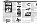
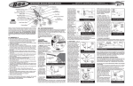
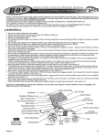
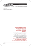
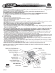
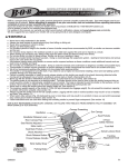
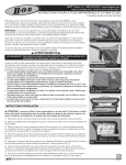
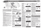
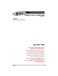
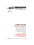
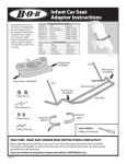
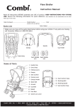
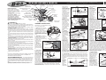
DUALLIE OWNERS MANUAL Handle Bar & Brake Lever Seat Tensioning Strap BOB is a company that Handlebar Release Lever produces high quality Canopy Flap products, which encourage a healthy, outdoor, car-free lifestyle. Seat Recline Adjusters In addition to strollers, we also make single-wheeled cargo trailers Slider Latch for bicycles. See www.bobgear.com for our complete Seat Back Pocket line of products. Before Shock Absorber attempting to assemble or use your new stroller, read and Frame Release Handle understand these operating Shock Release Button instructions completely to insure proper assembly and operation. Wrist Safety If you are unclear on any point, contact your Strap dealer or BOB before use. A.F.O.D. WARNINGS . Never leave children unattended in the stroller. . Failure to properly assemble or install the quick release wheels on this stroller may result in the wheels becoming detached while moving and a subsequent loss of control of the stroller. . Always use seat harness to avoid serious injury to child from sliding or falling out of stroller. . Never allow occupants to stand in stroller. . The parking brake is not designed as a stopping brake. The brake should not be used to slow or stop the stroller. The brake is intended to park the stroller on flat surfaces, not on inclines. Never leave your children in the stroller unattended with or without the parking brake set! . Do not attach parcels or bags to the handle or frame of stroller except those recommended by BOB, as stroller can become unstable and tip over. . The maximum load of the Duallie stroller is 100 lbs (45 kg). Do not exceed maximum load (occupant plus luggage weight) as stroller will become unstable. . Do not place sharp objects in the seatback pocket as your child leans against this and can be injured as a result. . When starting out, always make sure the childs hands and feet are away from wheels. . Follow instructions and use care when folding and unfolding stroller to prevent finger entrapment (see section 14). . The Duallie stroller is not equipped for use after dark. If you intend to use at night, we recommend installing a lighting system available through your local bike shop. . We do not recommend wearing roller skates or inline skates while pushing stroller. . Do not use stroller on stairs or steep inclines. Stroller can tip over, resulting in injury. . Never pull a loaded stroller backwards up stairs. Doing so could damage the suspension system leading to frame failure and serious injury to the user and/or the occupants. . Always use Wrist Safety Strap. BOB IS NOT RESPONSIBLE FOR INJURY, DAMAGE, OR FAILURE THAT RESULTS FROM OWNERS FAULTY ASSEMBLY OR MAINTENANCE AFTER SHIPPING. AGE RECOMMENDATIONS: - It is recommended that your child be a minimum of 6 to 8 weeks old before riding directly in the stroller seat. Young babies incapable of holding their head up must be provided additional head and neck support to ride safely. For jogging and off road use, children should be at least 6 to 8 months old. Children develop at different rates. Consult with your pediatrician regarding the suitability of the stroller use with your child. Canopy Drawstring(s) MA0670 Sun Canopy(s) Seat Pockets 5 Point Safety Harness Foot Well Fender & Brake Assembly Swing Arm Swing Arm Pivot Fig. 1 Low Boy Anatomy of the BOB Duallie ASSEMBLY INSTRUCTIONS: Reference Fig. 1 as it describes the various parts of the Duallie stroller. 1. UNPACK: Remove stroller, stroller wheels, front fender and front quick release from packaging. Plastic packaging material was used to protect the front fork dropouts, the front wheel axles and the shock slider brackets. Remove these plastic pieces. Position 1 Position 2 Shock Release Button 2. SWINGARM: Rotate the swingarm away from the front of Fig. 2 the stroller until the shocks Swingarm in unfolded position engage in the first position (Fig. with shock in position 1. 2). Each shock locking pin will snap and lock into position 1. 3. HANDLE: Rotate the stroller handle up to the fully open position. Slider Latches will lock into place (Fig. 3). (800) 893-2447 www.bobgear.com email- [email protected] Phone: (208) 375-5171 Fax: (208) 375-5172, BOB Trailers, Inc. 5475 Gage St. Boise, Idaho 83706 Handlebar Release Lever Slider Latch Fig. 3 Handlebar in the fully open position. 4. REAR WHEEL: Place the rear Quick Release Lever In wheel quick release Open Position lever in the open position, as shown in Fig. 4. Insert the rear wheels stub axle into the hole in the rear dropout. If the axle does not Adjusting Nut slide in easily, Fig. 4 Rear wheel Quick Release with loosen the quick lever in open position. release adjusting nut (Fig. 4) by hand. Re-insert the axle fully into the rear dropout until the axle shoulder or snap ring on the axle comes in contact with the dropout (Fig. 5). Move the quick release lever to the closed position (Fig. 6). The word CLOSE should be clearly visible and the quick release lever should almost touch dropout. When properly adjusted, it will require considerable Insert Wheel Dropout torque (80-105 in-lbs Fully or 9-12 Nm) to close the lever. If you do not feel this resistance (too loose Snap Ring or or too tight), return Axle Shoulder the quick release lever back to the Fig. 5 Rear wheel properly installed open position (Fig. (left side shown). 4), and adjust the adjusting nut (clockwise to Quick tighten, Release counterclockwise to loosen). Move the quick release lever to the closed position (Fig. 6). NOTE: Follow all instructions exactly. If you are unsure Fig. 6 Quick release in the how to operate the closed position (right side shown). quick release, consult your dealer or contact Fig. 7 Fender Screws BOB. Fabric Screw 5. FENDER INSTALLATION: Before installing Fabric Screw the front wheel, Fender Screws you will need to attach the fender. The two attachment screws can be found already installed on the Fig. 8 Fender Installation Metal Tab Hole frame (Fig. 7). Remove the two Cross Tube Hole Brake fender mounting Mounting Plate Hole screws. You may wish to remove a fabric screw (right Fender or left) to give better Screw access to the cross tube fender screw. Align the hole in the Fabric Screw metal tab of the Hole Fender Hole fender with the threaded hole in the center of the front cross tube and install screw (Fig. 8). Align the hole in the plastic fender with the hole in the brake mounting plate and install screw (Fig. 8). Center fender on stroller and tighten both screws. 6. FRONT WHEEL: (Fig. 9) shows the anatomy of the front wheel quick release. Remove the adjuster nut and one spring from the quick release, and install the quick release rod into the wheel axle. Install the spring (small end towards the center of the wheel) and screw on the adjuster nut by Adjusting Nut Rod Quick Release Lever turning in a clockwise direction. Tighten the nut only Conical three turns Springs Cam Housing (final adjustment Fig. 9 Front Quick Release Anatomy will be made after the wheel is 10 mm Nut Fig. 10 Caliper Brake Anatomy installed). Brake Body Barrel As the strollers Adjuster Brake & Fender tires are wider Mounting Screw Lock than the rims, and Nut as the brake pads are adjusted to Brake the rims, the Quick Release brake caliper will Brake Lever Pad Nut need to be Brake Pad opened before mounting or removing the wheel. Open the brake quick release (Fig. 10) by squeezing the brake pads Fork together with your right hand, Dropouts and pulling down and then rotating the brake quick release lever outward with your left hand. The front forks dropouts Quick are slotted to receive the front Adjusting Release wheel (Fig. 11). Slide the wheel Open Nut into the dropouts so that the quick release lever is on the left Fig. 11 Front fork dropouts shown hand side of the stroller. Make with wheel in position. Adjust nut snug sure the wheel is centered in with Quick Release in open position. the frame and that the axle is touching Quick the back of Release the dropout Closed slot. Securely tighten the wheel in Fork place as Tube follows: With the quick release lever Fig. 12 Quick Release in the closed in the open position and parallel to fork tube. position (Fig. 11), tighten the adjusting nut (clockwise) until it comes in contact with the dropout. Move the quick release lever to the closed position (Fig. 12). This should require significant pressure. If you do not feel significant resistance, turn the quick release lever back to the open position (Fig. 11), and hand tighten the adjusting nut by one or two more turns in the clockwise direction until snug. Move the quick release lever toward the closed position (Fig. 12). The word CLOSE should be clearly visible and the quick release lever should be parallel to the fork tube. It should require considerable torque (80-105 in-lbs or 912 Nm) to close the lever when properly adjusted. NOTE: Failure to properly adjust quick release may result in wheel loss and serious personal injury. If you are unsure how to operate the quick release, consult your dealer or call BOB. 7. PARKING BRAKE: The brake is a parking brake, it prevents the stroller from moving while loading and unloading it. The parking brake is not designed as a stopping brake. Do not use the brake to slow or stop the stroller. The brake is intended to park the stroller on flat surfaces not on inclines. Never leave your children in the stroller unattended Brake lever Brake Lever Body Lock Ring Barrel Adjuster Parking BrakeButton Fig. 13 Parking BrakeButton Fig. 14 Brake lever in the set position with button depressed. DUALLIE OWNERS MANUAL Handle Bar & Brake Lever Seat Tensioning Strap BOB is a company that Handlebar Release Lever produces high quality Canopy Flap products, which encourage a healthy, outdoor, car-free lifestyle. Seat Recline Adjusters In addition to strollers, we also make single-wheeled cargo trailers Slider Latch for bicycles. See www.bobgear.com for our complete Seat Back Pocket line of products. Before Shock Absorber attempting to assemble or use your new stroller, read and Frame Release Handle understand these operating Shock Release Button instructions completely to insure proper assembly and operation. Wrist Safety If you are unclear on any point, contact your Strap dealer or BOB before use. A.F.O.D. WARNINGS . Never leave children unattended in the stroller. . Failure to properly assemble or install the quick release wheels on this stroller may result in the wheels becoming detached while moving and a subsequent loss of control of the stroller. . Always use seat harness to avoid serious injury to child from sliding or falling out of stroller. . Never allow occupants to stand in stroller. . The parking brake is not designed as a stopping brake. The brake should not be used to slow or stop the stroller. The brake is intended to park the stroller on flat surfaces, not on inclines. Never leave your children in the stroller unattended with or without the parking brake set! . Do not attach parcels or bags to the handle or frame of stroller except those recommended by BOB, as stroller can become unstable and tip over. . The maximum load of the Duallie stroller is 100 lbs (45 kg). Do not exceed maximum load (occupant plus luggage weight) as stroller will become unstable. . Do not place sharp objects in the seatback pocket as your child leans against this and can be injured as a result. . When starting out, always make sure the childs hands and feet are away from wheels. . Follow instructions and use care when folding and unfolding stroller to prevent finger entrapment (see section 14). . The Duallie stroller is not equipped for use after dark. If you intend to use at night, we recommend installing a lighting system available through your local bike shop. . We do not recommend wearing roller skates or inline skates while pushing stroller. . Do not use stroller on stairs or steep inclines. Stroller can tip over, resulting in injury. . Never pull a loaded stroller backwards up stairs. Doing so could damage the suspension system leading to frame failure and serious injury to the user and/or the occupants. . Always use Wrist Safety Strap. BOB IS NOT RESPONSIBLE FOR INJURY, DAMAGE, OR FAILURE THAT RESULTS FROM OWNERS FAULTY ASSEMBLY OR MAINTENANCE AFTER SHIPPING. AGE RECOMMENDATIONS: - It is recommended that your child be a minimum of 6 to 8 weeks old before riding directly in the stroller seat. Young babies incapable of holding their head up must be provided additional head and neck support to ride safely. For jogging and off road use, children should be at least 6 to 8 months old. Children develop at different rates. Consult with your pediatrician regarding the suitability of the stroller use with your child. Canopy Drawstring(s) MA0670 Sun Canopy(s) Seat Pockets 5 Point Safety Harness Foot Well Fender & Brake Assembly Swing Arm Swing Arm Pivot Fig. 1 Low Boy Anatomy of the BOB Duallie ASSEMBLY INSTRUCTIONS: Reference Fig. 1 as it describes the various parts of the Duallie stroller. 1. UNPACK: Remove stroller, stroller wheels, front fender and front quick release from packaging. Plastic packaging material was used to protect the front fork dropouts, the front wheel axles and the shock slider brackets. Remove these plastic pieces. Position 1 Position 2 Shock Release Button 2. SWINGARM: Rotate the swingarm away from the front of Fig. 2 the stroller until the shocks Swingarm in unfolded position engage in the first position (Fig. with shock in position 1. 2). Each shock locking pin will snap and lock into position 1. 3. HANDLE: Rotate the stroller handle up to the fully open position. Slider Latches will lock into place (Fig. 3). (800) 893-2447 www.bobgear.com email- [email protected] Phone: (208) 375-5171 Fax: (208) 375-5172, BOB Trailers, Inc. 5475 Gage St. Boise, Idaho 83706 Handlebar Release Lever Slider Latch Fig. 3 Handlebar in the fully open position. 4. REAR WHEEL: Place the rear Quick Release Lever In wheel quick release Open Position lever in the open position, as shown in Fig. 4. Insert the rear wheels stub axle into the hole in the rear dropout. If the axle does not Adjusting Nut slide in easily, Fig. 4 Rear wheel Quick Release with loosen the quick lever in open position. release adjusting nut (Fig. 4) by hand. Re-insert the axle fully into the rear dropout until the axle shoulder or snap ring on the axle comes in contact with the dropout (Fig. 5). Move the quick release lever to the closed position (Fig. 6). The word CLOSE should be clearly visible and the quick release lever should almost touch dropout. When properly adjusted, it will require considerable Insert Wheel Dropout torque (80-105 in-lbs Fully or 9-12 Nm) to close the lever. If you do not feel this resistance (too loose Snap Ring or or too tight), return Axle Shoulder the quick release lever back to the Fig. 5 Rear wheel properly installed open position (Fig. (left side shown). 4), and adjust the adjusting nut (clockwise to Quick tighten, Release counterclockwise to loosen). Move the quick release lever to the closed position (Fig. 6). NOTE: Follow all instructions exactly. If you are unsure Fig. 6 Quick release in the how to operate the closed position (right side shown). quick release, consult your dealer or contact Fig. 7 Fender Screws BOB. Fabric Screw 5. FENDER INSTALLATION: Before installing Fabric Screw the front wheel, Fender Screws you will need to attach the fender. The two attachment screws can be found already installed on the Fig. 8 Fender Installation Metal Tab Hole frame (Fig. 7). Remove the two Cross Tube Hole Brake fender mounting Mounting Plate Hole screws. You may wish to remove a fabric screw (right Fender or left) to give better Screw access to the cross tube fender screw. Align the hole in the Fabric Screw metal tab of the Hole Fender Hole fender with the threaded hole in the center of the front cross tube and install screw (Fig. 8). Align the hole in the plastic fender with the hole in the brake mounting plate and install screw (Fig. 8). Center fender on stroller and tighten both screws. 6. FRONT WHEEL: (Fig. 9) shows the anatomy of the front wheel quick release. Remove the adjuster nut and one spring from the quick release, and install the quick release rod into the wheel axle. Install the spring (small end towards the center of the wheel) and screw on the adjuster nut by Adjusting Nut Rod Quick Release Lever turning in a clockwise direction. Tighten the nut only Conical three turns Springs Cam Housing (final adjustment Fig. 9 Front Quick Release Anatomy will be made after the wheel is 10 mm Nut Fig. 10 Caliper Brake Anatomy installed). Brake Body Barrel As the strollers Adjuster Brake & Fender tires are wider Mounting Screw Lock than the rims, and Nut as the brake pads are adjusted to Brake the rims, the Quick Release brake caliper will Brake Lever Pad Nut need to be Brake Pad opened before mounting or removing the wheel. Open the brake quick release (Fig. 10) by squeezing the brake pads Fork together with your right hand, Dropouts and pulling down and then rotating the brake quick release lever outward with your left hand. The front forks dropouts Quick are slotted to receive the front Adjusting Release wheel (Fig. 11). Slide the wheel Open Nut into the dropouts so that the quick release lever is on the left Fig. 11 Front fork dropouts shown hand side of the stroller. Make with wheel in position. Adjust nut snug sure the wheel is centered in with Quick Release in open position. the frame and that the axle is touching Quick the back of Release the dropout Closed slot. Securely tighten the wheel in Fork place as Tube follows: With the quick release lever Fig. 12 Quick Release in the closed in the open position and parallel to fork tube. position (Fig. 11), tighten the adjusting nut (clockwise) until it comes in contact with the dropout. Move the quick release lever to the closed position (Fig. 12). This should require significant pressure. If you do not feel significant resistance, turn the quick release lever back to the open position (Fig. 11), and hand tighten the adjusting nut by one or two more turns in the clockwise direction until snug. Move the quick release lever toward the closed position (Fig. 12). The word CLOSE should be clearly visible and the quick release lever should be parallel to the fork tube. It should require considerable torque (80-105 in-lbs or 912 Nm) to close the lever when properly adjusted. NOTE: Failure to properly adjust quick release may result in wheel loss and serious personal injury. If you are unsure how to operate the quick release, consult your dealer or call BOB. 7. PARKING BRAKE: The brake is a parking brake, it prevents the stroller from moving while loading and unloading it. The parking brake is not designed as a stopping brake. Do not use the brake to slow or stop the stroller. The brake is intended to park the stroller on flat surfaces not on inclines. Never leave your children in the stroller unattended Brake lever Brake Lever Body Lock Ring Barrel Adjuster Parking BrakeButton Fig. 13 Parking BrakeButton Fig. 14 Brake lever in the set position with button depressed. DUALLIE OWNERS MANUAL (800) 893-2447 www.bobgear.com email- [email protected] Phone: (208) 375-5171 Fax: (208) 375-5172, BOB Trailers, Inc. 5475 Gage St. Boise, Idaho 83706 MA0670 with or without the parking brake set! After installing the Brake Tire front wheel, the Body brake caliper will need to be placed Rim Brake in the closed Pad position. Close the 3/16 (5mm) brake quick release (Fig. 10) by Fig. 15 Clearance between brake pad & rim squeezing the brake pads against 10mm Caliper the wheel with one Mounting Nut hand, then rotate the brake quick release lever in the counter clockwise direction with your other hand until it Brake Pad Nut points downward. To set the parking brake, squeeze the Fig.16 Brake pads shown aligned to rim brake lever and press and hold the button down, then release lever (Fig. AFOD 13 &14). When the brake is properly set, the button will remain depressed Cross Tube and the lever will Wrist Strap appear as shown in Fig. 14. To release the parking Fig. 17 AFOD correctly attached brake, simply squeeze the brake lever and the button will pop up. For the parking brake to work correctly, it is critical that the brake be adjusted properly. Squeeze the brake lever and verify that the brake pads contact the rim as shown in Fig. 16. If they are misaligned, use a 10mm wrench to loosen brake pad nuts, slide pads into correct position and tighten securely. The cable tension is pre-adjusted at the factory yet the brake cable will need periodic adjustment (as the cable stretches slightly and the black cable housing compresses over time). To adjust cable tension, there are two barrel adjusters in the brake assembly (Fig. 10 &13). To tighten the cable, loosen the lock ring and turn the barrel adjuster in the counter clockwise direction. Secure the barrel adjuster in the new position by tightening the lock ring against the caliper or brake lever body. There should be a 3/16(5mm) clearance between the rim and brake pads as shown in Fig. 15. If gap is not equal on each brake pad, you can reposition the brake on the frame by loosening the 10 mm nut (Fig. 16) with a 10mm wrench, adjust to the gap shown in Fig. 15 and retighten the same nut. If you do not understand these instructions, or feel the brake is adjusted incorrectly, take the stroller to your dealer for proper adjustment. If your brake pads (Fig. 10) are worn, see your dealer for replacements. 8. AFOD: With the stroller in the fully open position (Fig. 1), attach the AFOD (Anti-Fly-Out-Device) around the cross tube with the plastic buckle (Fig. 17). It is important that the AFOD is always properly secured when using the stroller, as it is part of the childs seat restraint system. It is, however, necessary to release the AFOD in order to fold the stroller. Shoulder Strap Crotch Strap Buckle Fig. 18 Place straps over shoulders and secure to buckle. 9. SUN CANOPY: The Duallie features an independantly adjustable two position sun canopy for each seat. To fully open a canopy, rotate the assembly forward until the fabric is taut. The rear canopy flap should be freed from the Velcro to give additional sun protection. To reduce the size of a sun canopy, pull the canopy toward the handlebar. The additional fabric can be gathered by pulling the canopy drawstring (Fig. 1) and securing the cord lock. 10. SEAT TENSIONING: The seat compartments are divided by a section of nylon webbing that runs the length of the stroller. From time to time it may be necessary to increase the tension of the webbing. To adjust the tension start with handlebar in the fully open position as shown in Fig 3. At the top center of the seat the webbing loops over the handlebar cross tube and connects to a ladderlock buckle. Under the ladderlock buckle there is a tensioning strap. Pull on this strap to increase the tension. Shoulder Strap Fig. 19 Securely adjust shoulder straps Sternum Strap Fig. 20 Connect Sternum Strap Seat Reclining Ladder Locks 11. SEAT SAFETY HARNESS: Set parking brake before placing child in stroller. To secure your Fig. 21 child in the seat, put one shoulder strap over each shoulder and snap Reclining the male buckle into the female Strap Loops receiver on the crotch strap (Fig. 18). Adjust shoulder straps to be snug and secure (Fig. 19). Connect and adjust the sternum strap (red), see Fig. 20. WARNING: Never place passengers in the stroller without securing them in the harness. Fig. 22 Seat in fully reclined position. Unrestrained passengers can affect the control of the stroller. Passenger weight limit - 50 lbs (22.5 kg) per seat. Passenger height limit - 44 in. (112 cm) 12. RECLINING SEAT: Set parking brake before making any seat adjustments. To recline the seat, rotate the ladder lock buckles (Fig. 21) forward thus releasing the reclining straps. To raise the seat, pull the reclining strap loops until you obtain the desired position. The seat back can be adjusted to recline anywhere between the fully upright position and the fully reclined position (Fig. 21 & 22). Fig. 23 13. SHOCK ABSORBERS: Stroller with handle folded The suspension system features two shock positions to provide a comfortable ride for kids of different weights. The two positions are shown in Fig. 2. Position 1 is intended for total loads up to 50 lbs. (22.5 kg), while position 2 is intended for total loads from 50 to 100 lbs. (22.5 to 45 kg). The Duallie features a sliding track and spring loaded shock Pull Up pin that automatically locks in Sharply place when it aligns with either of the two shock positions. Shock position adjustments should be made with the Frame stroller unloaded. The shock Release Handle will lock into position 1 when AFOD Unbuckled unfolding the stroller. To use the stiffer shock position, move Fig. 24 the shock from position 1 to Pull handle upwards sharply to fold position 2 by depressing the shock release button (Fig. 2) with one hand, and with the other hand, lift slightly and pull the shock backward. When the shock pin is properly aligned in position 2, the pin will snap into place. Repeat this process for the second shock. To move the shock from position 2 to position 1, reverse the above process for both shocks. 14. FOLDING: Remove children from stroller. Remove the contents of the Low Boy cargo pouch. Unbuckle the AFOD strap (Fig. 17). The shock absorbers must be in Fig. 25 position 1 (Fig. 2) before folding. Stroller in fully folded position Press both the right and left handlebar release levers (Fig. 3), and fold the handlebar forward as shown in Fig. 23. Handlebar Locate the frame release handle underneath the seat (Fig. 24) and pull upwards sharply. This Cross Tube will allow the lower frame to fold together, Wrist Strap as shown in Fig. 25. Velcro The folded stroller can Fig. 26 Secure stroller in folded position be made even more compact by removing the front and rear wheels. To remove the front wheel, open the brake quick release (Fig. 10), open front wheel quick release, then pull the wheel forward (see section 6). Note that it is often easier to open the brake quick release before you fold the handlebar. The rear wheels are removed by opening the rear wheel quick release (Fig. 4), and pulling each wheel directly to the side. The Wrist Safety Strap can be used to lock the stroller in the folded position for transport and storage. With the stroller folded, loop the end of the wrist strap around the handlebar and back to the cross tube and fix the Velcro surfaces together (Fig. 26). 15. TIRE PRESSURE: IMPORTANT: Check tire pressure before every use. Keep all tires inflated to pressure specified on plastic rim or within the range embossed on the sidewall of the tire (usually 2535 p.s.i.) 16. STROLLER CARE and MAINTENANCE: The fabric is 100% polyester with a stain resistant treatment that makes cleanup easy. Use a sponge with a solution of mild soap and lukewarm water (maximum temperature of 100 deg. F / 38 deg. C). Rinse thoroughly with clean water to remove soap then air dry. Do not use detergent. Regular maintenance should include: Verifying tire pressure, verifying that all screws and fasteners are tight, and wiping parts clean with a rag. To reduce the possibility of squeaks, periodically apply a small amount of lubricant (Triflow, 3-in-one, or light sewing machine oil) to the pivot axles and interior faces of the pivot brackets, as shown in Fig. 27. Apply Lubricant STORAGE: It is best to Interior Faces of Bracket to store your stroller indoors when it is not in use. This will prolong its attractive appearance. Extended exposure to the sun's ultraviolet rays can fade and damage Apply Lubricant the fabric, tires, and to Axle plastic parts CARGO: The Duallie is Fig. 27 equipped with four small Lubrication Points pockets for the kids, a seatback pocket behind each seat and a Low Boy cargo pouch under the stroller. Adding weight to the seatback changes the center of gravity of the stroller, and increases the possibility that it will tip over backwards. For this reason, loads in the seatback pocket should never exceed two pounds (1 kg.). Although the seatback is padded, it is important to remember that this is what your child leans against. Never place sharp or injurious objects into the seatback pocket. Maximum load for Low Boy is 10 lbs (5.5 kg). LIMITED WARRANTY BOB Trailers Inc. takes pride in its workmanship and strives to manufacture the best products possible. Therefore, we warranty our Duallies against defects in material and workmanship subject to the conditions listed below. Since no product is indestructible, it does not cover defects attributable to or resulting from normal wear, abuse or alteration. . Frame is warranted for 5 years. . Components and fabric are warranted for one year. . Warranty is only valid for the original purchaser. . Proof of purchase is required to exercise this warranty. . Labor and freight charges are not included. . Normal wear, neglect, abuse, accidents, improper assembly or maintenance, or the installation of parts or accessories not compatible with the original intended use of the stroller, as sold, are not covered by this Warranty. . Warranty claims must be made through an authorized dealer. . This warranty is limited to the repair or replacement of the defective part. BOB shall in no event be responsible for consequential or special damages. . This Limited Warranty is the only express or implied warranty applicable to BOB. Any implied warranties, including warranties of merchantability and fitness shall be limited in scope and duration in accordance with this limited warranty. STROLLER ACCESSORIES BOB offers a complete line of accessories for your Duallie Stroller. Visit our website for full details, specs and images: www.bobgear.com HANDLEBAR CONSOLE At your finger tips storage for two water bottles or drinks and other small items. 4 Velcro straps for easy attachment. WARM FUZZY Warm Fuzzy Seat Insert -The ultimate in plushness & comfort. Thick, polypropylene fleece will give you and your child a warm fuzzy! WEATHER SHIELD Your little one will be dry & comfortable in bad weather, strolling with the BOB Weather Shield! SUN PROTECTOR Reduces up to 65% of solar heat and glare as well as UVA/UVB rays. Also protects children from brisk winds and flying insects. DUALLIE OWNERS MANUAL (800) 893-2447 www.bobgear.com email- [email protected] Phone: (208) 375-5171 Fax: (208) 375-5172, BOB Trailers, Inc. 5475 Gage St. Boise, Idaho 83706 MA0670 with or without the parking brake set! After installing the Brake Tire front wheel, the Body brake caliper will need to be placed Rim Brake in the closed Pad position. Close the 3/16 (5mm) brake quick release (Fig. 10) by Fig. 15 Clearance between brake pad & rim squeezing the brake pads against 10mm Caliper the wheel with one Mounting Nut hand, then rotate the brake quick release lever in the counter clockwise direction with your other hand until it Brake Pad Nut points downward. To set the parking brake, squeeze the Fig.16 Brake pads shown aligned to rim brake lever and press and hold the button down, then release lever (Fig. AFOD 13 &14). When the brake is properly set, the button will remain depressed Cross Tube and the lever will Wrist Strap appear as shown in Fig. 14. To release the parking Fig. 17 AFOD correctly attached brake, simply squeeze the brake lever and the button will pop up. For the parking brake to work correctly, it is critical that the brake be adjusted properly. Squeeze the brake lever and verify that the brake pads contact the rim as shown in Fig. 16. If they are misaligned, use a 10mm wrench to loosen brake pad nuts, slide pads into correct position and tighten securely. The cable tension is pre-adjusted at the factory yet the brake cable will need periodic adjustment (as the cable stretches slightly and the black cable housing compresses over time). To adjust cable tension, there are two barrel adjusters in the brake assembly (Fig. 10 &13). To tighten the cable, loosen the lock ring and turn the barrel adjuster in the counter clockwise direction. Secure the barrel adjuster in the new position by tightening the lock ring against the caliper or brake lever body. There should be a 3/16(5mm) clearance between the rim and brake pads as shown in Fig. 15. If gap is not equal on each brake pad, you can reposition the brake on the frame by loosening the 10 mm nut (Fig. 16) with a 10mm wrench, adjust to the gap shown in Fig. 15 and retighten the same nut. If you do not understand these instructions, or feel the brake is adjusted incorrectly, take the stroller to your dealer for proper adjustment. If your brake pads (Fig. 10) are worn, see your dealer for replacements. 8. AFOD: With the stroller in the fully open position (Fig. 1), attach the AFOD (Anti-Fly-Out-Device) around the cross tube with the plastic buckle (Fig. 17). It is important that the AFOD is always properly secured when using the stroller, as it is part of the childs seat restraint system. It is, however, necessary to release the AFOD in order to fold the stroller. Shoulder Strap Crotch Strap Buckle Fig. 18 Place straps over shoulders and secure to buckle. 9. SUN CANOPY: The Duallie features an independantly adjustable two position sun canopy for each seat. To fully open a canopy, rotate the assembly forward until the fabric is taut. The rear canopy flap should be freed from the Velcro to give additional sun protection. To reduce the size of a sun canopy, pull the canopy toward the handlebar. The additional fabric can be gathered by pulling the canopy drawstring (Fig. 1) and securing the cord lock. 10. SEAT TENSIONING: The seat compartments are divided by a section of nylon webbing that runs the length of the stroller. From time to time it may be necessary to increase the tension of the webbing. To adjust the tension start with handlebar in the fully open position as shown in Fig 3. At the top center of the seat the webbing loops over the handlebar cross tube and connects to a ladderlock buckle. Under the ladderlock buckle there is a tensioning strap. Pull on this strap to increase the tension. Shoulder Strap Fig. 19 Securely adjust shoulder straps Sternum Strap Fig. 20 Connect Sternum Strap Seat Reclining Ladder Locks 11. SEAT SAFETY HARNESS: Set parking brake before placing child in stroller. To secure your Fig. 21 child in the seat, put one shoulder strap over each shoulder and snap Reclining the male buckle into the female Strap Loops receiver on the crotch strap (Fig. 18). Adjust shoulder straps to be snug and secure (Fig. 19). Connect and adjust the sternum strap (red), see Fig. 20. WARNING: Never place passengers in the stroller without securing them in the harness. Fig. 22 Seat in fully reclined position. Unrestrained passengers can affect the control of the stroller. Passenger weight limit - 50 lbs (22.5 kg) per seat. Passenger height limit - 44 in. (112 cm) 12. RECLINING SEAT: Set parking brake before making any seat adjustments. To recline the seat, rotate the ladder lock buckles (Fig. 21) forward thus releasing the reclining straps. To raise the seat, pull the reclining strap loops until you obtain the desired position. The seat back can be adjusted to recline anywhere between the fully upright position and the fully reclined position (Fig. 21 & 22). Fig. 23 13. SHOCK ABSORBERS: Stroller with handle folded The suspension system features two shock positions to provide a comfortable ride for kids of different weights. The two positions are shown in Fig. 2. Position 1 is intended for total loads up to 50 lbs. (22.5 kg), while position 2 is intended for total loads from 50 to 100 lbs. (22.5 to 45 kg). The Duallie features a sliding track and spring loaded shock Pull Up pin that automatically locks in Sharply place when it aligns with either of the two shock positions. Shock position adjustments should be made with the Frame stroller unloaded. The shock Release Handle will lock into position 1 when AFOD Unbuckled unfolding the stroller. To use the stiffer shock position, move Fig. 24 the shock from position 1 to Pull handle upwards sharply to fold position 2 by depressing the shock release button (Fig. 2) with one hand, and with the other hand, lift slightly and pull the shock backward. When the shock pin is properly aligned in position 2, the pin will snap into place. Repeat this process for the second shock. To move the shock from position 2 to position 1, reverse the above process for both shocks. 14. FOLDING: Remove children from stroller. Remove the contents of the Low Boy cargo pouch. Unbuckle the AFOD strap (Fig. 17). The shock absorbers must be in Fig. 25 position 1 (Fig. 2) before folding. Stroller in fully folded position Press both the right and left handlebar release levers (Fig. 3), and fold the handlebar forward as shown in Fig. 23. Handlebar Locate the frame release handle underneath the seat (Fig. 24) and pull upwards sharply. This Cross Tube will allow the lower frame to fold together, Wrist Strap as shown in Fig. 25. Velcro The folded stroller can Fig. 26 Secure stroller in folded position be made even more compact by removing the front and rear wheels. To remove the front wheel, open the brake quick release (Fig. 10), open front wheel quick release, then pull the wheel forward (see section 6). Note that it is often easier to open the brake quick release before you fold the handlebar. The rear wheels are removed by opening the rear wheel quick release (Fig. 4), and pulling each wheel directly to the side. The Wrist Safety Strap can be used to lock the stroller in the folded position for transport and storage. With the stroller folded, loop the end of the wrist strap around the handlebar and back to the cross tube and fix the Velcro surfaces together (Fig. 26). 15. TIRE PRESSURE: IMPORTANT: Check tire pressure before every use. Keep all tires inflated to pressure specified on plastic rim or within the range embossed on the sidewall of the tire (usually 2535 p.s.i.) 16. STROLLER CARE and MAINTENANCE: The fabric is 100% polyester with a stain resistant treatment that makes cleanup easy. Use a sponge with a solution of mild soap and lukewarm water (maximum temperature of 100 deg. F / 38 deg. C). Rinse thoroughly with clean water to remove soap then air dry. Do not use detergent. Regular maintenance should include: Verifying tire pressure, verifying that all screws and fasteners are tight, and wiping parts clean with a rag. To reduce the possibility of squeaks, periodically apply a small amount of lubricant (Triflow, 3-in-one, or light sewing machine oil) to the pivot axles and interior faces of the pivot brackets, as shown in Fig. 27. Apply Lubricant STORAGE: It is best to Interior Faces of Bracket to store your stroller indoors when it is not in use. This will prolong its attractive appearance. Extended exposure to the sun's ultraviolet rays can fade and damage Apply Lubricant the fabric, tires, and to Axle plastic parts CARGO: The Duallie is Fig. 27 equipped with four small Lubrication Points pockets for the kids, a seatback pocket behind each seat and a Low Boy cargo pouch under the stroller. Adding weight to the seatback changes the center of gravity of the stroller, and increases the possibility that it will tip over backwards. For this reason, loads in the seatback pocket should never exceed two pounds (1 kg.). Although the seatback is padded, it is important to remember that this is what your child leans against. Never place sharp or injurious objects into the seatback pocket. Maximum load for Low Boy is 10 lbs (5.5 kg). LIMITED WARRANTY BOB Trailers Inc. takes pride in its workmanship and strives to manufacture the best products possible. Therefore, we warranty our Duallies against defects in material and workmanship subject to the conditions listed below. Since no product is indestructible, it does not cover defects attributable to or resulting from normal wear, abuse or alteration. . Frame is warranted for 5 years. . Components and fabric are warranted for one year. . Warranty is only valid for the original purchaser. . Proof of purchase is required to exercise this warranty. . Labor and freight charges are not included. . Normal wear, neglect, abuse, accidents, improper assembly or maintenance, or the installation of parts or accessories not compatible with the original intended use of the stroller, as sold, are not covered by this Warranty. . Warranty claims must be made through an authorized dealer. . This warranty is limited to the repair or replacement of the defective part. BOB shall in no event be responsible for consequential or special damages. . This Limited Warranty is the only express or implied warranty applicable to BOB. Any implied warranties, including warranties of merchantability and fitness shall be limited in scope and duration in accordance with this limited warranty. STROLLER ACCESSORIES BOB offers a complete line of accessories for your Duallie Stroller. Visit our website for full details, specs and images: www.bobgear.com HANDLEBAR CONSOLE At your finger tips storage for two water bottles or drinks and other small items. 4 Velcro straps for easy attachment. WARM FUZZY Warm Fuzzy Seat Insert -The ultimate in plushness & comfort. Thick, polypropylene fleece will give you and your child a warm fuzzy! WEATHER SHIELD Your little one will be dry & comfortable in bad weather, strolling with the BOB Weather Shield! SUN PROTECTOR Reduces up to 65% of solar heat and glare as well as UVA/UVB rays. Also protects children from brisk winds and flying insects. tracking instructions MA0501A (800) 893-2447 www.bobgear.com email- [email protected] Phone: (208) 375-5171 Fax: (208) 375-5172, BOB Trailers, Inc. 5475 Gage St. Boise, Idaho 83706 We have added an enhanced feature to our jogging strollers that allows the customer to fine tune the tracking of their stroller. This document is designed to supplement to the Owners Manual. Proceed with initial setup and use of your stroller and only refer to this document if you believe there is a tracking problem with your stroller. All fixed three wheeled vehicles can be easily influenced to deviate from a straight path. In some cases strollers can have or develop a tendency to pull to the right/left due to many different factors including tire pressure, wheel installation, road conditions and manufacturing tolerances. If you find your BOB stroller to significantly track or pull to the left or right during use on flat terrain, follow the sequence of instructions below. Tracking Adjustment Instructions: front wheel, secure the wheel and brake quick release levers. b. Perform roll test again. If the stroller still consistently pulls to the left or right when pushed straight, proceed to next step. 7) Fine tune tracking of stroller is accomplished by using the adjustment knobs shown in Fig. 4. Rotate axle 90o Fig. 2 Rotate Axle The fine-tuning of desired tracking should be performed in the following sequence. 1) Confirm the rear wheels are installed correctly. Refer to step 4 of the Owners Manual for installation instructions. 2) Confirm the front wheel is installed correctly. Refer to step 6 of the Owners Manual for correct installation instructions. When tightening the quick release make sure the front wheel is pushed straight and equally toward the back of the dropouts. Wheel Reoriented With Quck Release Lever On Opposite Side 3) Check the tire pressure, making sure the tire pressure is exactly the same on all three tires. 4) Roll test the stroller as described below. It is recommended you have someone assist with this task in order to catch and return the stroller. Fig. 1 illustrates the roll test process. Top View Of Stroller 90o Wheel axles perpendicular to straight line Stroller pulls to right Stroller pulls to left 16 Fig. 1 Stroller Roll Test a. Empty the stroller. Do not roll test with a child or any occupant in the stroller. b. Find a location on level ground approximately 16 ft. long. It is helpful to use an existing straight-line as a frame of reference such as the edge of the sidewalk or a painted line in a playground. c. Align the stroller so the rear wheels are perpendicular to the straight line. Push and release the stroller trying carefully not to influence its direction to the left or right so it rolls straight down the test path. This step should be performed more than once to make sure the stroller was not biased left or right by the pushing action. d. If the stroller consistently pulls to the left or right when pushed straight, proceed with the steps below until tracking is satisfactory. Fig 1. illustrates how to interpret the results. Reference convention: Left and right are described as viewed from the operators frame of reference (behind the stroller). Example: The parking brake lever is on the left side of the handlebar. 5) Rotate the front axle. Often tracking can be corrected by simply rotating the front wheel axle. a. Open the front wheel quick release, step 6 of the Owners Manual. Rotate axle 90 degrees in dropout, Fig. 2 and retighten quick release. b. Perform roll testing again. If the stroller still consistently pulls to the left or right when pushed straight, proceed to next step. 6) Reorient the front wheel. Many times the tracking can be corrected by removing the front wheel and flipping it around and reinstalling it. a. Open the front wheel and front brake quick releases, step 6 of the Owners Manual. Remove the front wheel and flip it around so the quick release lever is on the opposite side, Fig. 3. Reinstall the Fig. 3 Reorient Front Wheel If your stroller pulls to the right, proceed as follows: Front Wheel a. Open quick release lever on front wheel, step 6 in the Owners Manual. It is not necessary to remove the front wheel. b. Turn the right knob clockwise 1-full turn, as shown in Fig. 5, thereby pushing the right side of the wheel forward. Retighten quick release. c. Repeat Roll test. If stroller still pulls to the right, repeat steps A and B. Left Adjust Knob (Fig. 6) Right Adjust Knob (Fig. 5) Fig 4. Adjust Knobs If your stroller pulls to the left, proceed as follows: a. Open quick release lever on front wheel, step 6 in the Owners Manual. It is not necessary to remove the front wheel. b. Turn the left knob clockwise 1-full turn, as shown in Fig. 6, thereby pushing the left side of the wheel forward. Retighten quick release. Turn Knob Clockwise 1 Full turn Fig. 5 Right Adjust Knob c. Repeat Roll test. If stroller still pulls to the left, repeat steps A and B. Turn Knob Clockwise 1 Full turn Fig. 6 Left Adjust Knob