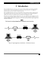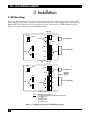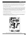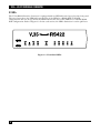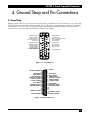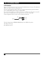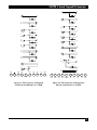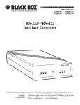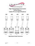
1
NOVEMBER 1995
IC483A
IC483AE
IC483C
IC481A-R2
IC481C-R2
V.35↔RS-422 Interface Converter
CUSTOMER
SUPPORT
INFORMATION
Order toll-free in the U.S.: Call 877-877-BBOX (outside U.S. call 724-746-5500)
FREE technical support 24 hours a day, 7 days a week: Call 724-746-5500 or fax 724-746-0746
Mailing address: Black Box Corporation, 1000 Park Drive, Lawrence, PA 15055-1018
Web site: www.blackbox.com • E-mail: [email protected]
FEDERAL COMMUNICATIONS COMMISSION
AND
CANADIAN DEPARTMENT OF COMMUNICATIONS
RADIO FREQUENCY INTERFERENCE STATEMENTS
This equipment generates, uses, and can radiate radio frequency energy and if not installed and used properly,
that is, in strict accordance with the manufacturer’s instructions, may cause interference to radio communication.
It has been tested and found to comply with the limits for a Class A computing device in accordance with the
specifications in Subpart J of Part 15 of FCC rules, which are designed to provide reasonable protection against
such interference when the equipment is operated in a commercial environment. Operation of this equipment in
a residential area is likely to cause interference, in which case the user at his own expense will be required to take
whatever measures may be necessary to correct the interference.
Changes or modifications not expressly approved by the party responsible for compliance could void the user’s
authority to operate the equipment.
This digital apparatus does not exceed the Class A limits for radio noise emission from digital apparatus set out in the Radio
Interference Regulation of the Canadian Department of Communications.
Le présent appareil numérique n’émet pas de bruits radioélectriques dépassant les limites applicables aux appareils numériques de
classe A prescrites dans le Règlement sur le brouillage radioélectrique publié par le ministère des Communications du Canada.
INSTRUCCIONES DE SEGURIDAD (Normas Oficiales Mexicanas Electrical Safety Statement)
1. Todas las instrucciones de seguridad y operación
deberán ser leídas antes de que el aparato eléctrico
sea operado.
2. Las instrucciones de seguridad y operación
deberán ser guardadas para referencia futura.
3. Todas las advertencias en el aparato eléctrico y en
sus instrucciones de operación deben ser
respetadas.
4. Todas las instrucciones de operación y uso deben
ser seguidas.
5. El aparato eléctrico no deberá ser usado cerca del
agua—por ejemplo, cerca de la tina de baño,
lavabo, sótano mojado o cerca de una alberca, etc..
6. El aparato eléctrico debe ser usado únicamente
con carritos o pedestales que sean recomendados
por el fabricante.
7. El aparato eléctrico debe ser montado a la pared o
al techo sólo como sea recomendado por el
fabricante.
8. Servicio—El usuario no debe intentar dar servicio
al equipo eléctrico más allá a lo descrito en las
instrucciones de operación. Todo otro servicio
deberá ser referido a personal de servicio
calificado.
9. El aparato eléctrico debe ser situado de tal manera
que su posición no interfiera su uso. La colocación
del aparato eléctrico sobre una cama, sofá,
alfombra o superficie similar puede bloquea la
ventilación, no se debe colocar en libreros o
gabinetes que impidan el flujo de aire por los
orificios de ventilación.
10. El equipo eléctrico deber ser situado fuera del
alcance de fuentes de calor como radiadores,
registros de calor, estufas u otros aparatos
(incluyendo amplificadores) que producen calor.
11. El aparato eléctrico deberá ser connectado a una
fuente de poder sólo del tipo descrito en el
instructivo de operación, o como se indique en el
aparato.
12. Precaución debe ser tomada de tal manera que la
tierra fisica y la polarización del equipo no sea
eliminada.
13. Los cables de la fuente de poder deben ser guiados
de tal manera que no sean pisados ni pellizcados
por objetos colocados sobre o contra ellos,
poniendo particular atención a los contactos y
receptáculos donde salen del aparato.
14. El equipo eléctrico debe ser limpiado únicamente
de acuerdo a las recomendaciones del fabricante.
15. En caso de existir, una antena externa deberá ser
localizada lejos de las lineas de energia.
16. El cable de corriente deberá ser desconectado del
cuando el equipo no sea usado por un largo
periodo de tiempo.
17. Cuidado debe ser tomado de tal manera que
objectos liquidos no sean derramados sobre la
cubierta u orificios de ventilación.
18. Servicio por personal calificado deberá ser provisto
cuando:
A: El cable de poder o el contacto ha sido dañado;
u
B: Objectos han caído o líquido ha sido
derramado dentro del aparato; o
C: El aparato ha sido expuesto a la lluvia; o
D: El aparato parece no operar normalmente o
muestra un cambio en su desempeño; o
E: El aparato ha sido tirado o su cubierta ha sido
dañada.
V.35↔RS-422 INTERFACE CONVERTER
TRADEMARKS USED IN THIS MANUAL
Any trademarks mentioned in this manual are acknowledged to be the property of the trademark owners
CONTENTS
Contents
Chapter
Page
1.
SPECIFICATIONS ......................................................................................................................................4
2.
INTRODUCTION ......................................................................................................................................5
3.
INSTALLATION.........................................................................................................................................6
3.1
DIP Shunt Settings........................................................................................................................6
3.2
LEDs ..............................................................................................................................................8
4.
GROUND STRAP AND PIN CONNECTIONS ........................................................................................9
4.1
Ground Strap ................................................................................................................................9
4.2
Pin Connections..........................................................................................................................10
3
V.35↔RS422 INTERFACE CONVERTER
1. Specifications
Speed —
Up to 2.5 Mbps
Maximum
Transmission
Rate —
Approximately 2.455 Mbps
Interface —
RS-422, V.35
Connectors —
IC481A-R2:
RS-422: (1) DB37 female (pinned to RS-449 specifications);
V.35: (1) male 34-pin “M” block
IC483A:
RS-422: (1) DB37 female (pinned to RS-449 specifications);
V.35: (1) female 34-pin “M” block
Controls —
Jumpers for Pin H Support
V.35 port DTE/DCE jumper-selectable
RS-422 port DTE/DCE jumper-selectable
Maximum Storage
Temperature —
158°F (70°C)
Maximum
Operating
Temperature —
122°F (50°C)
Power —
IC481A-R2, IC483A: 115-VAC, 60-Hz, 16-watt power supply;
IC483AE: 230-VAC, 50 Hz, 16-watt power supply;
IC481C-R2, IC483C: Requires 16 watts from RM060 interface
Size —
Standalone: 2.3"H x 8"W x 11.9"D (5.8 x 20.3 x 30.2 cm)
Rackmount Card: 7.5"W x 10.5"D (19.1 x 26.7 cm)
Weight —
2 lb. (0.9 kg)
4
CHAPTER 2: Introduction
2. Introduction
The V.35↔RS-422 Interface Converter comes in both 115-VAC (IC483A) and 230-VAC (IC483AE)
standalone units. A card version (IC483C) is available for rackmounting. The rack (RM060) is
switch-selectable for either 115-VAC or 230-VAC operation.
The V.35↔RS-422 Interface Converter provides bidirectional conversion of all the commonly used
V.35 and RS-422 signals. The unit operates with one port configured as Data Terminal Equipment
(DTE) and the other port configured as Data Communications Equipment (DCE).
The unit has two jumper-selectable configurations. One connects RS-422 modem equipment to V.35
terminal equipment (DCE to DTE). The other connects V.35 modem equipment to RS-422 terminal
equipment (DTE to DCE). Both configurations allow bidirectional data transfer. Typical applications
are shown in Figure 2-1.
NOTE
The Converter is configured opposite of the equipment you are connecting.
RS-422/V.35
RS-422
MODEM
(DCE)
DTE
DCE
V.35
TERMINAL
COMPUTER
(DTE)
RS-422/V.35
RS-422
TERMINAL
COMPUTER
(DTE)
DCE
DTE
V.35
MODEM
DSU
(DCE)
Figure 2-1. Typical Applications of the RS-422<—>V.35 Interface Converter.
5
V.35↔RS422 INTERFACE CONVERTER
3. Installation
3.1 DIP Shunt Settings
The V.35↔RS-422 Interface Converter has two jumper selectable configurations determined by DIP
shunt settings located inside the unit on the printed circuit board. One configuration is for connecting
RS-422 DTE to V.35 DCE. The second configuration is for connecting V.35 DTE to RS-422 DCE. See
Figure 3-1 for more information on DIP Shunt settings.
DTE DCE
A
B
V.35 DTE
STEP 1
XW5
V.35 CONNECTOR
STEP 2
XW6
XW4
W1
A
B
C
XW3
RS-422 CONNECTOR
STEP 4
XW2
W2
A
B
C
STEP 3
XW1
If V.35 is DTE
OR
DTE DCE
A
B
XW6
STEP 1
XW5
STEP 2
422 DTE
XW4
V.35 CONNECTOR
FACTORY
DEFAULT
SETTING
W1
A
B
C
XW3
RS-422 CONNECTOR
STEP 4
W2
STEP 3
A
B
C
XW2
XW1
If RS232 is DTE
STEP 4 Pin H Supported (As shipped)
W1 in BC Position (DTR passed from V.35 to RS-422 port)
W2 in AB Position
OR
Pin H Not Supported
W1 in AB position
W2 in BC Position
Figure 3-1. Quick Setup Guide for DIP Shunt Settings.
6
CHAPTER 3: Installation
To install the V.35↔RS-422 Interface Converter, follow these steps and refer to Figures 3-1 and 3-2.
1. Set jumper XW6 to V.35 side when configuring the V.35 side of the unit as DTE. Set XW6 to the 422 side
when configuring the RS422 side of the unit as DTE. Jumper XW6 affects only the front panel LEDs.
2 & 3. When configuring V.35 as DTE and RS-422 as DCE, set jumpers in sockets labeled XW1B,
XW2B, XW3B, XW4A, and XW5A.
When configuring V.35 as DCE and RS-422 as DTE, set jumpers XW1A, XW2A, XW3A, XW4B, and XW5B.
4. Jumper W1 is used if the V.35 side of the Converter is DCE. If W1 is in the B-C position, the DTR signal
(pin H) is passed from the V.35 port through to pins 12 and 30 of the RS-422 port. If W1 is placed in
the A-B position, pins 12 and 30 are forced high. When the V.35 side is configured as DTE, W1 has no
effect and W2 is used instead. With W2 in the A-B position, the terminal ready (DTR) signal is passed
from the RS-422 side of the V.35 port. With W2 in the B-C position, Pin H is forced high.
5. Attach the cable from the RS-422 device to the 37-pin female receptacle (J1) on the rear panel of the
V.35↔RS-422 Interface Converter.
6. Attach the cable from the V.35 device to the 34-pin female M-block connector (J2) on the rear panel
of the V,35↔RS-422 Interface Converter.
W2
XW6
W1
DTE DCE
RX
J2
J1
V.
3
5
RS
4
4
9
7. Plug the 4-pin power cord into the receptacle on the rear panel of the case. Do not plug the power
module into an AC outlet yet. After the DIP shunts are set as explained in Section 3.1, plug the
power module into an AC outlet. The unit is now ready to use.
Figure 3-2. Board Layout Showing LED Indicators and Plug Connectors.
7
V.35↔RS422 INTERFACE CONVERTER
3.2 LEDs
The V.35↔RS-422 Interface Converter is equipped with ten LED indicators located on the front panel.
The row of type above the LEDs indicates the uses of the LEDs for a RS422 DTE/V.35 DCE
configuration. The row of type below the LEDs indicates the uses of the LEDs for a V.35DTE/RS422
DCE configuration. Refer to Figure 3-3. In the card version, the LED’s distinction is on the pull lever.
Figure 3-3. Front Panel LEDs.
8
CHAPTER 4: Ground Strap and Pin Connections
4. Ground Strap and Pin Connections
4.1 Ground Strap
Signal grounds (Pins 19, 20, and 37 on the 422 interface and Pin B on the V.35 interface) are connected
together, but not connected to chassis ground (Pin A). However, for applications requiring the grounds
at a common reference point, the grounds can be connected by installing a jumper strap across W3
located at the rear of the printed circuit board between J1 and P1.
CHASSIS GROUND
REQUEST TO SEND
DATA SET READY
DATA TERMINAL READY
TEST MODE
A
C
E
H
K
B
D
F
J
L
SIGNAL GROUND
CLEAR TO SEND
RECEIVE LINE SIGNAL DETECT
LOCAL LOOPBACK
TEST PATTERN
TRANSMITTED DATA P
TRANSMITTED DATA S
TRANSMIT TIMING U
TRANSMIT TIMING W
TRANSMIT TIMING Y
TRANSMIT
TIMING AA
AA
REMOTE
LOOPBACK
R
T
V
X
RECEIVED DATA
RECEIVED DATA
RECEIVE TIMING
RECEIVE TIMING
BB
REMOTE LOOPBACK
Figure 4-1. V.35 Interface
RECEIVE COMMON 20
21
SEND DATA 22
SEND TIMING 23
RECEIVE DATA 24
REQUEST TO SEND 25
RECEIVE TIMING 26
CLEAR TO SEND 27
28
DATA MODE 29
TERMINAL READY 30
RECEIVER READY 31
32
33
34
TERMINAL TIMING 35
36
SEND COMMON 37
1
2
3
4
5
6
7
8
9
10
11
12
13
14
15
16
17
18
19
SHIELD
SEND DATA
SEND TIMING
RECEIVE DATA
REQUEST TO SEND
RECEIVE TIMING
CLEAR TO SEND
DATA MODE
TERMINAL READY
RECEIVER READY
TERMINAL TIMING
SIGNAL GROUND
Figure 4-2. RS-422 Interface.
9
V.35↔RS422 INTERFACE CONVERTER
4.2 Pin Connections
Figures 4-1 and 4-2 show the pin connections for the V.35↔RS-422 Interface Converter. The illuminated
LEDs in these figures indicate incoming signals only.
The unit is shipped without the jumper (Rx) between signal ground and chassis ground. The RS-422
port is configured DTE and the V.35 port is configured DCE.
For operation with the RS422 port as DCE and the V.35 port as DTE, the signal directions are reversed1.
Pins 12 and 30 of the RS422 port become inputs which are connected to a status LED.
1
In this configuration, W1 has no effect on the circuit W2 is used instead.
W2
A
Pin 30
B
Pin H
Pin 12
C
The unit is shipped with the TERMINAL READY jumper in the TRUE (ON) position.
AB - DTR passed through
BC - DTR always asserted
10
CHAPTER 4: Ground Strap and Pin Connections
4
22
4
22
P
S
P
S
DS5
DS6
TD
6
24
R
T
R
T
DS6
DS5
C
C
DS3
DS1
D
D
DS1
DS3
E
E
DS9
13
31
DS4
DS2
F
DS4
RR
Y
AA
DS8
V
X
V
X
DS7
12
DS7
RC
17
35
12
30
CTS
DS1
DS2
RTS
RR
DS3
DS4
30
U
W
C
A
DS10
TC
8
26
TC
8
26
SD
5
23
Y
AA
DS8
DSR
13
31
DTR/DM
F
5
23
CTS
11
29
CTS
11
29
RTS
9
27
RTS
9
27
RD
7
25
RD
7
25
TD
6
24
RC
A
B
W2
H
C
C
H
B
W1
DS9
TD
RD
RC
TC
DM
DS5
DS6
DS7
DS8
DS9
POWER
Figure 4-1. The Converter Configured
for RS-422 as DTE and V.35 as DCE.
DM/DTR
17
35
U
W
DS1
DS2
DS3
DS4
DS10
DS5
DS6
DS7
DS8
DS9
RTS
DSR
CTS
SD
POWER
RD
TD
RC
TC
DTR
Figure 4-2. The Converter Configured for
RS-422 as DCE and V.35 as DTE.
11
© Copyright 1995. Black Box Corporation. All rights reserved.
1000 Park Drive
•
Lawrence, PA 15055-1018
•
724-746-5500
•
Fax 724-746-0746