1
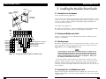
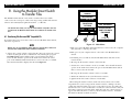
APRIL 2000
SW925A
SW925AE
SW926C
SW927C
SW928C
SW929C
Modular Smart Switch
itch
art Sw
lar Sm
Modu
POWER
1/4
1
2
3
4
5
6
7
8
9
10
11
ER
BUFF 4
3/
1/2
F
12
© Copyright 2000. Black Box Corporation. All rights reserved.
1000 Park Drive
•
Lawrence, PA 15055-1018
•
724-746-5500
•
Fax 724-746-0746
CUSTOMER
SUPPORT
INFORMATION
Order toll-free in the U.S.: Call 877-877-BBOX (outside U.S. call 724-746-5500)
FREE technical support 24 hours a day, 7 days a week: Call 724-746-5500 or fax 724-746-0746
Mailing address: Black Box Corporation, 1000 Park Drive, Lawrence, PA 15055-1018
Web site: www.blackbox.com • E-mail: [email protected]
MODULAR SMART SWITCH
FEDERAL COMMUNICATIONS COMMISSION
AND
INDUSTRY CANADA
RADIO FREQUENCY INTERFERENCE STATEMENTS
This equipment generates, uses, and can radiate radio-frequency energy, and if not
installed and used properly, that is, in strict accordance with the manufacturer’s
instructions, may cause interference to radio communication. It has been tested
and found to comply with the limits for a Class A computing device in accordance
with the specifications in Subpart B of Part 15 of FCC rules, which are designed to
provide reasonable protection against such interference when the equipment is
operated in a commercial environment. Operation of this equipment in a
residential area is likely to cause interference, in which case the user at his own
expense will be required to take whatever measures may be necessary to correct
the interference.
Changes or modifications not expressly approved by the party responsible
for compliance could void the user’s authority to operate the equipment.
This digital apparatus does not exceed the Class A limits for radio noise emission from
digital apparatus set out in the Radio Interference Regulation of Industry Canada.
Le présent appareil numérique n’émet pas de bruits radioélectriques dépassant les limites
applicables aux appareils numériques de la classe A prescrites dans le Règlement sur le
brouillage radioélectrique publié par Industrie Canada.
1
MODULAR SMART SWITCH
NORMAS OFICIALES MEXICANAS (NOM)
ELECTRICAL SAFETY STATEMENT
INSTRUCCIONES DE SEGURIDAD
1. Todas las instrucciones de seguridad y operación deberán ser leídas antes de
que el aparato eléctrico sea operado.
2. Las instrucciones de seguridad y operación deberán ser guardadas para
referencia futura.
3. Todas las advertencias en el aparato eléctrico y en sus instrucciones de
operación deben ser respetadas.
4. Todas las instrucciones de operación y uso deben ser seguidas.
5. El aparato eléctrico no deberá ser usado cerca del agua—por ejemplo, cerca
de la tina de baño, lavabo, sótano mojado o cerca de una alberca, etc..
MODULAR SMART SWITCH
12. Precaución debe ser tomada de tal manera que la tierra fisica y la polarización
del equipo no sea eliminada.
13. Los cables de la fuente de poder deben ser guiados de tal manera que no
sean pisados ni pellizcados por objetos colocados sobre o contra ellos,
poniendo particular atención a los contactos y receptáculos donde salen del
aparato.
14. El equipo eléctrico debe ser limpiado únicamente de acuerdo a las
recomendaciones del fabricante.
15. En caso de existir, una antena externa deberá ser localizada lejos de las lineas
de energia.
16. El cable de corriente deberá ser desconectado del cuando el equipo no sea
usado por un largo periodo de tiempo.
17. Cuidado debe ser tomado de tal manera que objectos liquidos no sean
derramados sobre la cubierta u orificios de ventilación.
18. Servicio por personal calificado deberá ser provisto cuando:
A: El cable de poder o el contacto ha sido dañado; u
6. El aparato eléctrico debe ser usado únicamente con carritos o pedestales que
sean recomendados por el fabricante.
B: Objectos han caído o líquido ha sido derramado dentro del aparato; o
7. El aparato eléctrico debe ser montado a la pared o al techo sólo como sea
recomendado por el fabricante.
D: El aparato parece no operar normalmente o muestra un cambio en su
desempeño; o
8. Servicio—El usuario no debe intentar dar servicio al equipo eléctrico más allá
a lo descrito en las instrucciones de operación. Todo otro servicio deberá ser
referido a personal de servicio calificado.
E: El aparato ha sido tirado o su cubierta ha sido dañada.
C: El aparato ha sido expuesto a la lluvia; o
9. El aparato eléctrico debe ser situado de tal manera que su posición no
interfiera su uso. La colocación del aparato eléctrico sobre una cama, sofá,
alfombra o superficie similar puede bloquea la ventilación, no se debe colocar
en libreros o gabinetes que impidan el flujo de aire por los orificios de
ventilación.
10. El equipo eléctrico deber ser situado fuera del alcance de fuentes de calor
como radiadores, registros de calor, estufas u otros aparatos (incluyendo
amplificadores) que producen calor.
11. El aparato eléctrico deberá ser connectado a una fuente de poder sólo del
tipo descrito en el instructivo de operación, o como se indique en el aparato.
2
3
MODULAR SMART SWITCH
TRADEMARKS USED IN THIS MANUAL
Any trademarks mentioned in this manual are acknowledged to be the property of the
trademark owners.
MODULAR SMART SWITCH
Contents
Chapter
Page
1. Specifications . . . . . . . . . . . . . . . . . . . . . . . . . . . . . . . . . . . . . . . . . . . . . . . . .8
2. Introduction . . . . . . . . . . . . . . . . . . . . . . . . . . . . . . . . . . . . . . . . . . . . . . . . . .9
2.1 Features . . . . . . . . . . . . . . . . . . . . . . . . . . . . . . . . . . . . . . . . . . . . . . . . . .9
2.2 Product Information . . . . . . . . . . . . . . . . . . . . . . . . . . . . . . . . . . . . . . .9
3. Installing Port Modules and Memory . . . . . . . . . . . . . . . . . . . . . . . . . . . . .11
3.1 Fitting Expansion-Buffer Memory . . . . . . . . . . . . . . . . . . . . . . . . . . .11
3.2 Fitting Port Modules . . . . . . . . . . . . . . . . . . . . . . . . . . . . . . . . . . . . . .12
4. Configuring the Modular Smart Switch . . . . . . . . . . . . . . . . . . . . . . . . . . .14
4.1 Setting the Global Timeout Period . . . . . . . . . . . . . . . . . . . . . . . . . . .15
4.2 Setting Parallel Ports as Inputs or Outputs . . . . . . . . . . . . . . . . . . . .17
4.3 Setting Serial Port Protocols and Options . . . . . . . . . . . . . . . . . . . . .18
5. Installing the Modular Smart Switch . . . . . . . . . . . . . . . . . . . . . . . . . . . . .21
5.1 Selecting Ports for Your Equipment . . . . . . . . . . . . . . . . . . . . . . . . . .21
5.2 Positioning the Modular Smart Switch . . . . . . . . . . . . . . . . . . . . . . . .21
5.3 Cable Requirements . . . . . . . . . . . . . . . . . . . . . . . . . . . . . . . . . . . . . . .21
5.4 Connecting Devices to the Modular Smart Switch . . . . . . . . . . . . . .21
5.5 Switching On . . . . . . . . . . . . . . . . . . . . . . . . . . . . . . . . . . . . . . . . . . . .22
5.6 Enabling Computers . . . . . . . . . . . . . . . . . . . . . . . . . . . . . . . . . . . . . .22
5.7 Using the Modular Smart Switch . . . . . . . . . . . . . . . . . . . . . . . . . . . .24
5.8 Port Indicators (1 to 12) . . . . . . . . . . . . . . . . . . . . . . . . . . . . . . . . . . .24
5.9 Buffer Status Indicators . . . . . . . . . . . . . . . . . . . . . . . . . . . . . . . . . . . .25
6. Using the Control Software . . . . . . . . . . . . . . . . . . . . . . . . . . . . . . . . . . . . .26
6.1 Installing the Resident Software . . . . . . . . . . . . . . . . . . . . . . . . . . . . .26
6.2 Running the Software from the DOS Prompt . . . . . . . . . . . . . . . . . .26
6.3 Command-Line Options . . . . . . . . . . . . . . . . . . . . . . . . . . . . . . . . . . .27
6.4 Running the Software from within Microsoft® Windows . . . . . . . . . .28
6.5 Using the Software . . . . . . . . . . . . . . . . . . . . . . . . . . . . . . . . . . . . . . . .29
6.6 Main Menu . . . . . . . . . . . . . . . . . . . . . . . . . . . . . . . . . . . . . . . . . . . . . .30
6.7 Selecting a Destination Printer, Plotter, or Modem . . . . . . . . . . . . .31
6.8 Direct Output of Typed Keyboard Characters . . . . . . . . . . . . . . . . . .33
6.9 Using the Functions Menu . . . . . . . . . . . . . . . . . . . . . . . . . . . . . . . . .34
6.9.1 Sending a Form Feed . . . . . . . . . . . . . . . . . . . . . . . . . . . . . . . . .34
6.9.2 Clearing Unwanted Data . . . . . . . . . . . . . . . . . . . . . . . . . . . . . .34
6.9.3 Ending Long or Infinite Timeouts . . . . . . . . . . . . . . . . . . . . . .34
6.10 Setting the Options . . . . . . . . . . . . . . . . . . . . . . . . . . . . . . . . . . . . . . .35
6.10.1 Multiple Copies . . . . . . . . . . . . . . . . . . . . . . . . . . . . . . . . . . . .35
6.10.2 Changing the Timeout . . . . . . . . . . . . . . . . . . . . . . . . . . . . . .36
6.10.3 Selecting a PC Port . . . . . . . . . . . . . . . . . . . . . . . . . . . . . . . . .36
4
5
MODULAR SMART SWITCH
Chapter
Page
7. Serial Port Control Utility . . . . . . . . . . . . . . . . . . . . . . . . . . . . . . . . . . . . . .37
8. Using the Modular Smart Switch to Transfer Files . . . . . . . . . . . . . . . . . .40
8.1 Transferring Files between IBM compatible PCs . . . . . . . . . . . . . . . .40
8.2 Using the Software with File-Transfer Software . . . . . . . . . . . . . . . . .42
8.3 Transferring Files Between PCs Not Compatible
with IBM . . . . . . . . . . . . . . . . . . . . . . . . . . . . . . . . . . . . . . . . . . . . . . . .42
8.4 General Hints and Tips . . . . . . . . . . . . . . . . . . . . . . . . . . . . . . . . . . . .43
9. Software Commands . . . . . . . . . . . . . . . . . . . . . . . . . . . . . . . . . . . . . . . . . .44
9.1 Introduction . . . . . . . . . . . . . . . . . . . . . . . . . . . . . . . . . . . . . . . . . . . . .44
9.2 Connect Command . . . . . . . . . . . . . . . . . . . . . . . . . . . . . . . . . . . . . . .45
9.2.1 Selecting a Destination Port . . . . . . . . . . . . . . . . . . . . . . . . . . .45
9.2.2 Printing Several Copies . . . . . . . . . . . . . . . . . . . . . . . . . . . . . . .45
9.2.3 Broadcasting Data to Several Devices . . . . . . . . . . . . . . . . . . . .45
9.2.4 Varying the Timeout Period . . . . . . . . . . . . . . . . . . . . . . . . . . .46
9.2.5 Disabling Software Commands . . . . . . . . . . . . . . . . . . . . . . . . .46
9.2.6 Removing Line Feeds at End of Software
Commands . . . . . . . . . . . . . . . . . . . . . . . . . . . . . . . . . . . . . . . . . . .47
9.3 Clear Command . . . . . . . . . . . . . . . . . . . . . . . . . . . . . . . . . . . . . . . . . .47
9.4 End of File Command . . . . . . . . . . . . . . . . . . . . . . . . . . . . . . . . . . . . .47
9.5 Creating Batch Files to Send Commands (IBM
compatible PCs) . . . . . . . . . . . . . . . . . . . . . . . . . . . . . . . . . . . . . . . . . .47
9.6 Setting Default Start of Day Destination Ports . . . . . . . . . . . . . . . . . .49
MODULAR SMART SWITCH
Chapter
Page
Appendix A: Serial Ports ..................................................................................53
A.1 RS-232 and RS-422 Pin Assignments....................................................53
A.2 Connecting to Computers—RS-232 Connections ..............................54
A.2.1 RS-232 Connections to IBM PCs and Compatibles ..................54
A.2.2 RS-232 Connectors to IBM AT and compatibles ......................55
A.3 Connecting to Printers .........................................................................56
A.4 Connecting to Modems ........................................................................57
A.5 Connecting to Plotters..........................................................................58
A.6 Connecting to NEC Spinwriter ............................................................59
A.7 Connecting to DEC LN03 Laser Printer .............................................60
A.8 RS-422 Cables ........................................................................................61
Appendix B: Parallel Ports ...............................................................................62
B.1 Parallel Pin Assignments ......................................................................62
B.2 Cable for IBM PC/XT, AT, or compatible..........................................64
B.3 Cable to a 36-pin Amphenol ................................................................64
10. Troubleshooting . . . . . . . . . . . . . . . . . . . . . . . . . . . . . . . . . . . . . . . . . . . .50
10.1 Self-Test at Power-On . . . . . . . . . . . . . . . . . . . . . . . . . . . . . . . . . . . . .50
10.2 Parallel Interfaces—No Data Transmitted through the
Switch . . . . . . . . . . . . . . . . . . . . . . . . . . . . . . . . . . . . . . . . . . . . . . . . . .50
10.3 Parallel Interfaces—Corrupted, Extra, or Lost Data . . . . . . . . . . . .51
10.4 Problems Interfacing Serial Devices . . . . . . . . . . . . . . . . . . . . . . . . .51
10.5 Serial Interfaces—No Data Transmitted through the
Switch . . . . . . . . . . . . . . . . . . . . . . . . . . . . . . . . . . . . . . . . . . . . . . . . . .51
10.6 Serial Interfaces—Corrupted Data . . . . . . . . . . . . . . . . . . . . . . . . . .51
10.7 Merged Printouts . . . . . . . . . . . . . . . . . . . . . . . . . . . . . . . . . . . . . . . .52
10.8 Print Data Transmitted but File Transfer Fails . . . . . . . . . . . . . . . .52
6
7
MODULAR SMART SWITCH
MODULAR SMART SWITCH
1. Specifications
Base Chassis (SW925A/SW925AE)—6 dual-port module slots, 2 memory
module slots, integral power supply
Ports—Parallel: Dual parallel-port module slots with DB25 female connectors.
Automatic in/out detection or selectable by option switches. 30,000 cps.
Serial: Dual serial-port modules contain 2 bidirectional RS-232/422
interfaces with DB25 male connectors.
Switches—Control protocol and RS-232/422 selection and baud rates.
Baud Rates—300, 1200, 2400, 4800, 9600, 19200, 38400, and 57600 bps
Handshake—CTS/DTR hardware XON/XOFF, ETX/ATK.
Functional Features—Code-string control; data broadcast to multiple ports;
print to first available printer; file transfer compatible with Laplink,
Fastlynx, Kermit, Xmodem, etc.
Timeout—Selectable from 1 to 255 seconds
Indicators—LEDs: Buffer status, individual channel activity, power
2. Introduction
The Modular Smart Switch is suitable for a wide variety of applications,
including printer and plotter sharing, file transfer, modem sharing, network
switching, electronic point-of-sale systems, access control networks, machine
tool control, data collection, and mainframe connections.
2.1 Features
• Modular and user-upgradeable construction.
• Mixed serial (RS-232/422) and parallel ports in any combination.
• Up to 12 ports and 4 MB of buffer memory.
• Automatic printer and plotter sharing.
• Any port can be routed to any other port.
• File transfer between computers using standard file-transfer software.
• Memory-resident control software for selecting destination ports.
• Multiple copies of printouts.
Power—115 or 230 VAC, 60/50 Hz
• Unwanted print data can be cleared from the switch’s buffer.
Size—3.5"H x 13.1"W x 9.4"D (9 x 33.5 x 24 cm)
• Software for high-speed serial data output from PCs.
Weight—7.7 lb. (3.5 kg)
• Full-duplex serial data communications.
2.2 Product Information
The following items are available:
• Modular Smart Switch Chassis w/ 1 Meg Memory (SW925A, SW925AE)
includes:
Main chassis with 6 dual-port module slots and 2 memory slots
Software disk in 3.5" format
Power lead with 115 VAC or 230 VAC plug
5 module blanking plates with fixing screws
This user manual
8
9
MODULAR SMART SWITCH
• Dual Serial RS232/422 Port Module (SW926C)
• Dual Parallel Port Module In/Out (SW927C)
• 1 Meg Memory Expansion (SW928C)
• 2 Meg Memory Expansion (SW929C)
MODULAR SMART SWITCH
3. Installing Memory and Port Modules
To fit memory and port modules, you will need to remove the lid of your
Modular Smart Switch. To do this, remove the four retaining screws holding
the lid in place (see Figure 3-2) and lift the lid away.
3.1 Fitting Expansion-Buffer Memory
The Modular Smart Switch contains two memory module slots (A and B),
each of which can be fitted with a 1 MB or 2MB buffer memory module (see
Figure 3-1). The Modular Smart Switch is supplied as standard with a 1 Meg
buffer memory module fitted in slot A.
Memory slot B
Memory slot A
(fill this first)
Figure 3-1. Fitting Expansion Buffer Memory Modules.
10
11
MODULAR SMART SWITCH
MODULAR SMART SWITCH
To install additional buffer memory:
• Make sure that the Modular Smart Switch is powered off.
• Insert the expansion buffer memory module into slot A or B (slot A
should be filled first). A polarizing pin ensures that the board is seated
correctly.
The installed buffer memory is automatically tested whenever the Modular
Smart Switch is powered on. The buffer memory indicators will flash while
the test is in progress and go off when the test is complete. If all the channel
and buffer indicators come on permanently, then the buffer has been
installed incorrectly or there is a memory fault.
CAUTION
Always observe static handling precautions when installing memory
modules.
Position of lid
retaining screws
1. Keep the modules in their anti-static bags until you are ready to install
them.
2. Never place memory modules in plastic bags or on plastic surfaces.
3. Discharge static from your clothes before handling the modules (you
can do this by touching an earth-grounded metal device).
3.2 Fitting Port Modules
Figure 3-2. Fitting Port Modules.
To fit port modules:
1. Make sure that the Modular Smart Switch is powered off.
2. Remove the rear- panel blanking plates as appropriate.
• Any type of port module can be fitted into any of the six module slots in
any order.
3. Insert the modules as shown in Figure 3-2.
• All slots have equal priority.
4. Push the modules onto the mating connectors on the base board.
Do not place too much pressure on the board.
• All print data is routed by default to port 1 unless a destination port has
been selected. For automatic printer and plotter sharing, the printer or
plotter should be connected to port 1.
5. Fix the modules to the rear panel using the screws provided.
12
13
MODULAR SMART SWITCH
MODULAR SMART SWITCH
4. Configuring the Modular Smart Switch
4.1 Setting the Global Timeout Period
The ports on the Modular Smart Switch are configured using a number
of option switches situated on the modules. In addition to the port
configuration, the global timeout values can be set using option switches
on the main board. Figures 4-1, 4-2, and 4-3 show the meaning of each
of the sets of option switches. Set the option switches as required.
NOTE
The option switches are only read when the Modular Smart Switch is first
powered on. Changing the settings while the Modular Smart Switch is
powered on will have no immediate effect.
OFF
(0)
ON
(1)
0
0
1
1
0
1
0
1
Timeout = 16 seconds
Timeout = 30 seconds
Timeout = 1 minute
Timeout = 4 minutes
1
2
3
4
Reserved - set to 0
5
6
TEST switch - set to 0 (OFF)
for normal operation
Figure 4-1. Setting the Global Timeout Period.
14
15
MODULAR SMART SWITCH
Timeout Period
When a user has sent no data for the timeout period, the Modular Smart
Switch is able to switch to another user. The default timeout setting of 16
seconds is suitable for most applications. If printouts are ever merged,
increase the timeout period. Switches 1 and 2 on the base board control the
global default timeout period used by all the ports. Individual port timeouts
can be set using the software (see Chapter 6) or by sending software
commands (see Chapter 9).
MODULAR SMART SWITCH
4.2 Setting Parallel Ports as Inputs or Outputs
LOW port
HIGH port
LOW port
switches
HIGH port
switches
Dual parallel
port module
OFF
(0)
ON
(1)
1
2
3
4
ON
HIGH port switches
Set port as INPUT 1 0
Set port as OUTPUT 0 1
Automatic input/output 1 1
detection (* not guaranteed)
LOW port switches
1 0
0 1
1 1
Set port as INPUT
Set port as OUTPUT
Automatic input/output
detection (* not guaranteed)
Figure 4-2. Selecting the Direction of Parallel Ports (Input or Output).
16
17
MODULAR SMART SWITCH
MODULAR SMART SWITCH
NOTE
NOTE
Automatic detection of the direction of parallel ports is achieved by
detecting the state of the SELECT IN signal on the hardware interface.
This will operate with most PCs and printers. Automatic detection is not
guaranteed to work with all equipment, so if you experience any
problems, set the ports as dedicated inputs or outputs.
The XON/XOFF setting for printer and plotter con-nections is a
bidirectional protocol that recognizes the XON and XOFF characters in
both directions. The XON/XOFF setting for com-puter connections
recog-nizes the XON and XOFF characters in one direction only. This
allows graphics, font and other non text data to be sent from computers
without problems (the XON and XOFF characters often form part of this
data).
4.3 Setting Serial-Port Protocols and Options
Protocols
For serial devices, you must set a number of parameters to make sure that the
Modular Smart Switch is “speaking the same language” as the equipment that
it will communicate with. These parameters include the handshake mode,
the baud rate, the parity, the number of bits per character, and the number of
stop bits. Most computers and printers are able to set these parameters, so it
is generally advisable to set the fastest available. This is often 9600 baud, 8
bits per character, one stop bit, no parity, and either hardware handshake or
XON/XOFF.
Hardware Handshake
Ports on the Modular Smart Switch that are set to XON/XOFF handshake
will also give the hardware handshake signal to ensure maximum
compatibility.
The bidirectional XON/XOFF protocol used for printer and plotter connections can also be used for computer connections if the computer will
never send the XON or XOFF characters as part of the data stream.)
RS-232/RS-422 Selection
Each dual serial module supports both RS-232 and RS-422 serial
communication. The hardware signals for RS-232 and RS-422
communication appear on different pins of the interface
(see Appendix A for pin-configuration details).
• DTR/CTS (hardware) handshake uses hardware signal lines to control the
flow of data (pins 5 and 20).
Software Handshake
• ETX/ACK—the flow of data is controlled by sending blocks of data and
waiting for an ACKnowledgement character to be received.
• XON/XOFF (printer and plotter connections)—the flow of data is
controlled by the receiving device by transmitting XOFF (stop data flow)
and XON (start data flow) characters. Set this protocol on ports
connected to printers and plotters.
• XON/XOFF (computer connections)—the flow of data is controlled by
the Modular Smart Switch. This is done by sending XON (start data flow)
and XOFF (stop data flow) characters to the computer. Set this protocol
on ports connected to computers.
18
19
MODULAR SMART SWITCH
MODULAR SMART SWITCH
5. Installing the Modular Smart Switch
LOW port
HIGH port
HIGH port
LOW port switches
switches
5.1 Selecting Ports for Your Equipment
Printer and Plotter Sharing Applications
Dual serial
port module
Unless otherwise specified, all print and plot data will automatically be routed
to port 1. If you are automatically sharing a single printer or plotter, connect
it to port 1. All ports have equal priority and data output is handled on a
“first-come-first-served” basis.
General Datacomm Applications
For applications involving a central controlling PC, the PC should normally
be connected to port 1 since data is routed to this port by default.
OFF
(0)
ON
(1)
57k6 baud
38k4 baud
19k2 baud
9k6 baud
4k8 baud
2k4 baud
1k2 baud
300 baud
0
0
0
0
1
1
1
1
1
2
3
4
5
6
7
8
9 10
ON
0
0
1
1
0
0
1
1
0
1
0
1
0
1
0
1
5.2 Positioning the Modular Smart Switch
Choose a central position for the Modular Smart Switch. This keeps cable
lengths to a minimum.
7 bits
8 bits
0
1
2 stop bits 0
1 stop bit 1
0 RS422
1 RS232
0
0
1
1
0
1
0
1
XON/XOFF-printer/plotter connections
XON/XOFF-computer connections
ETX/ACK handshake
DTR/CTS handshake
Even parity 0 0
Odd parity 0 1
No parity
1 1
Figure 4-3. Setting Serial Port Options and Protocols.
5.3 Cable Requirements
You will need a suitable cable for each device that you wish to connect to the
switch. Mechanical and electrical specifications for the cables are given in
Appendix A (serial) and Appendix B (parallel).
NOTE
A great number of serial cables are available that are not suitable for use
with your Modular Smart Switch. Do not assume that an existing cable is
of the correct type because it has the correct connectors on each end or
because it works between two other pieces of equipment. Always use
the cabling recommended in this manual.
Centronics parallel cables should be less than 22.9 ft. (7 m) long. If the
parallel computer or printer is more than 22.9 ft. (7 m) from the switch, the
cable may be susceptible to spurious pick-up such as that generated from
switching on fluorescent lights. Reduce the cable runs or use a booster if you
have problems.
5.4 Connecting Devices to the Modular Smart Switch
Switch off all computers and printers before making any connections to the
Modular Smart Switch. Also, park any hard disks if you need to move any PCs
to allow access.
20
21
MODULAR SMART SWITCH
MODULAR SMART SWITCH
Plug in your cables, making sure that you are using the correct type of cable
(see Appendixes A and B) and that you are connecting to the right type of
port.
CAUTION
Connecting to the wrong type of port could damage both the Modular
Smart Switch and your computers and printers.
MODE COM1:9600,N,8,1,P <enter>
This sets the baud to 9600, no parity, 8 bits per character, and 1 stop bit on
COM1. You may wish to put this in your computer’s AUTOEXEC.BAT file.
You may wish to use the supplied software to enhance the speed and
functionality of your serial port (refer to Chapter 7 for full details on the
benefits of using the software utility).
ADMODE COM1:57600,N,8,1 <enter>
5.5 Switching On
Plug the power supply lead into the rear of the Modular Smart Switch. Plug
the power lead into a suitable supply socket. Switch on at the supply. Switch
on the Modular Smart Switch using the switch at the rear.
The Power indicator (green) should come on and stay on. The Buffer
Status indicators (red) should flicker for a few seconds while the unit selftests, and then go out.
It is generally better to switch on all your devices together or switch on the
Modular Smart Switch last.
5.6 Enabling Computers
Computers Connected to Parallel Ports
Parallel interfaces do not normally need to be configured. For IBM PCs
running DOS, make sure that PC timeouts do not occur if the Modular Smart
Switch’s buffer becomes full. This can be done using the MODE command
as follows. Refer to your DOS manual for details.
MODE LPT1: , , P
Computers Connected to Serial Ports
Each computer must communicate with the Modular Smart Switch in the
format expected by the port it is connected to. The baud rate, parity, bits per
character, stop bits, and handshake format must be the same on the
computer and the Modular Smart Switch port. Your computer instruction
manual will tell you how to set up these parameters.
If you have more than one port on your PC, make sure that your printout is
sent to a port that is connected to the Modular Smart Switch. For IBM
compatible PCs, DOS will prompt you to specify the printer port the first time
you issue a print command. If you are using a parallel port (LPT1, LPT2, or
LPT3), you can print directly without any further setup. If you are normally
using a serial port to output print data, you may wish to redirect the parallel
port data to output on the serial port, using the MODE command. The
following example will set your PC to send all LPT1 data to COM1.
MODE LPT1:=COM1:
If you are going to plot/print from DOS, make sure that the computer
cannot timeout if the buffer on the Modular Smart Switch becomes full. This
could cause errors on your plots or an error message to be displayed on your
screen. To avoid this, make sure that you have issued a MODE command with
the P option set. If you wish to run your serial port at a high baud rate and
make sure that no computer times out, you can use the MODE and ADMODE
commands together. The ADMODE protocol will always override the MODE
protocol. The following example would set COM1 to 57600 baud, no parity,
8 bits, 1 stop bit, and no application timeout.
MODE COM1:9600,N,8,1,P <enter>
ADMODE COM1:57600,N,8,1 <enter>
NOTE
If you are sending plot/print data from IBM compatibles using a serial
port, make sure that your AUTOEXEC.BAT includes both the MODE (with
P option) and ADMODE commands relevant to that port.
For IBM PCs and compatibles, the MODE command is used to select the
correct parameters. With the default option-switch settings and output on
COM1, the MODE command is:
22
23
MODULAR SMART SWITCH
MODULAR SMART SWITCH
5.7 Using the Modular Smart Switch
5.9 Buffer Status Indicators
Printer and Plotter Sharing Applications
The buffer status indicators show the state of the internal buffer memory in
the form of a bar graph:
The Modular Smart Switch is now ready for use as a printer sharer for the
printer attached to port 1. Data sent in from any computer will automatically
be sent to this port.
Users can print simultaneously, and the Modular Smart Switch will buffer
the information until it can be sent to the default printer/plotter. All data
from one source is treated as a single printable file until there has been a
break in the transmission for more than the timeout period (see Section 4.1).
If two or more printers/plotters are connected to the Modular Smart
Switch, you will need the software (see Chapter 6) or software commands (see
Chapter 9) to select between them. Other options and facilities are also
detailed in these two sections.
General Datacomm Applications
• 1⁄4 Indicator—Buffer is over 1/4 full
• 1⁄2 Indicator—Buffer is over 1/2 full
• 3⁄4 Indicator—Buffer is over 3/4 full
• F (full) Indicator—Buffer is completely full
If the buffer often fills to the 3⁄4 level, consider purchasing additional
memory for increased performance.
NOTE
The Modular Smart Switch will always operate correctly even if the buffer
becomes full. If you have any problems when the buffer memory is full,
check the handshaking settings on your equipment and your cabling.
Once you are communicating correctly with the Modular Smart Switch, you
can select between ports by sending ASCII command strings. In addition to
the data destination, these ASCII command strings can be used to select the
timeout period, “broadcast” data to several ports, and make/break permanent
(no timeout) connections. The serial ports on the Modular Smart Switch are
bidirectional. Refer to Chapter 7 for details on how to use the command
strings and the connection options available.
5.8 Port Indicators (1 to 12)
The port indicators can be off, on, or flashing.
• Off—When a port indicator is off, nothing is being transferred into or out
of that port and no data is available.
• On—The port indicator is on when data is available. If data has been sent
in on a port, the activity light will remain on until the port has timed out
(after no data has been sent for the timeout period).
• Flashing—While data is being transferred either into or out of the Modular
Smart Switch, the activity indicator will flash.
24
25
MODULAR SMART SWITCH
MODULAR SMART SWITCH
6. Using the Control Software
The control software is located on the disk supplied with your Modular Smart
Switch. It provides an easy and user-friendly way of operating the switch. It is
designed for use on IBM compatible PCs using CGA, EGA, VGA, and
monochrome adapters (it will also run on adapters that emulate the modes
used by these adapters). Its primary function is to enable destination devices
to be selected.
Installing the utility in your PC’s memory as a “resident program” allows
you to “pop up” the control software program at any time using a “hotkey”
combination. The utility supports options that allow the software to run as a
non-resident program from the DOS prompt (see Section 6.2) and while in
the Microsoft Windows environment (see Section 6.4).
6.3 Command-Line Options
The control software supports a number of command line options that allow
the utility to be installed and run in several different formats. They also allow
a number of default settings to be changed and different hotkey
combinations to be selected. Options are specified after a forward slash on
the command line. Any number of options can be specified. For example,
the following command line would install the utility for use in text modes
with COM2 as the default port and the hotkey combination set to
<CTRL><SHIFT>.
ADMENU /T /C2 /H2
The options available are summarized below. The default settings
(shown in brackets) are assumed for all the options that are not specified.
/U
6.1 Installing the Resident Software
Copy the program ADMENU.COM from the disk to the current directory
on your PC.
At the DOS prompt, type ADMENU <enter>
(No default)
Deletes the utility from memory.
/T and /G
(/G default)
The program will respond by printing an identification message. This
command only needs to be issued once. You may therefore find it convenient
to include it in your AUTOEXEC.BAT file. To invoke the ADMENU software,
press these three keys together:
The /G option allows the resident software to be used in both text and
graphics modes. When installed with the /G option, the software will
occupy 22K of memory. Installing the software with the /T option allows the
control software to be used in text modes only, and the memory requirement
is reduced to 10K. The memory size used is confirmed in the installation
message.
<CTRL><ALT><SHIFT>
/Lx and /Cx (/L1 default) x=1, 2, or 3
NOTE
You can change the hotkey combination used to invoke the ADMENU
software if required (see Section 6.3).
6.2 Running the Control Software from the DOS Prompt
Copy the program ADMENU.COM from the disk to the current directory
on your PC.
These options specify the PC port that is displayed when the control software
is initially invoked (either COM1, COM2, LPT1, LPT2, or LPT3). The
number of the required port is specified after the letter C or L: C for serial, L
for parallel. The port to be used can be specified once the software has been
invoked using the PC PORT function and so these options are primarily for
convenience only.
/Hx
(/H1 default)
At the DOS prompt, type ADMENU /N <enter>.
26
27
MODULAR SMART SWITCH
This option allows the hotkey combination that invokes the resident control
software to be changed. There are 5 possible options. The desired option is
selected by specifying the corresponding number after the letter H. The
available hotkey combinations are as follows.
/H1 selects <CTRL><ALT>
<SHIFT>
/H2 selects <CTRL><SHIFT>
/H3 selects <CTRL><ALT>
/H4 selects <CTRL><ALT>
/H5 selects <LEFT SHIFT>
<RIGHT SHIFT>
<SHIFT> can be either the left or the right shift key. The selected
combination is confirmed in the installation message.
/N and /R
(/R default)
These options allow the control software to be run as a non-resident utility.
To do this, use the /N option. To install the menu as a resident program, use
the /R option.
/M
(standard color default)
The /M ensures that the menu appears in mono mode. This option is
provided for compatibility with certain types of monochrome screens found
on some LAPTOPS and other computers. If the control software’s menu bars
are faint or non-existent on your screen, then install the software using the
/M option.
MODULAR SMART SWITCH
To use HOTKEY within Windows, you must first install the control software
in your computer’s memory. Do this before you run Windows, because once
you are within Windows, resident programs cannot be loaded. You can then
activate HOTKEY by clicking on HOTKEY.COM, HOTKEY.PIF, or an icon
associated with these files.
The control software can also be run as a non-resident utility from the
Windows desktop. To do this, click on ADWIN.PIF or an icon associated with
this file.
NOTE
For Windows 3 users, the easiest way to create an icon associated with
HOTKEY.COM is to make a copy of a current file on the desktop and then
to edit the properties of that file. For example, change the description to
ADMENU and the group file command line to C:\WINDOWS\HOTKEY.
COM.
6.5 Using the Control Software
Invoking the control software will cause a menu to appear on the screen.
You can select options from the menu using the <up> and <down> cursor
keys and the <enter> key.
• Use the <up> and <down> cursor keys to highlight the options in the
menus.
• Use <enter> to select a highlighted option.
• Use <escape> to quit from any menu or the application.
6.4 Running the Control Software from within Microsoft® Windows®
By using an additional utility (HOTKEY), you can invoke the resident control
software within Windows. It is equivalent to pressing the hotkey combination
that would normally be used to launch the control software.
Hotkey-activated programs cannot be used from the Windows desktop,
since Windows takes over full control of the keyboard, effectively locking
other programs out. HOTKEY overcomes this problem by allowing the
software to be invoked from an icon (or file name) while at the Windows
desktop. HOTKEY remembers previous settings and retains these between
applications. On some computers with additional memory, HOTKEY will run
within a window. Switching to a full-screen application while within Windows,
or quitting from Windows, will enable the hotkey combination to invoke the
menu.
28
29
MODULAR SMART SWITCH
MODULAR SMART SWITCH
6.6 Main Menu
F. Destination Port—Indicates the port on the Modular Smart Switch that
your PC is currently connected to. All data output from the currently
selected PC port (G) will be routed to this destination port on the
Modular Smart Switch.
ADDER TECHNOLOGY
ADMENU
A
DESTINATION
FILE TRANSFER
DIRECT OUTPUT
FUNCTIONS
OPTIONS
B
PORT 2
C
D
LPT1
E
<ESC> TO QUIT
F
G
H
Figure 6-1. Main Menu.
A. Destination—Used to connect your computer to the required printer,
plotter, modem, or other device (see Section 6.7).
B. File Transfer—Used to connect through to other computers and set the
Modular Smart Switch to file-transfer mode. This option should only be
used to establish links for file-transfer purposes—use the DESTINATION
option for all other applications (see Chapter 8). File transfer is only
available on serial ports.
G. PC Port—Indicates the port on your PC that the control software will use
to send control commands to your Modular Smart Switch. Make sure that
the port that is physically connected to the Modular Smart Switch is
displayed in this box.
H. Mode—Indicates whether normal mode or file-transfer mode is
currently selected. In normal mode, a dash (-) will be displayed. In filetransfer mode, a flashing arrow will be displayed. The mode in use is set
automatically when you select a destination port using the
DESTINATION (normal mode) or FILE TRANSFER option.
6.7 Selecting a Destination Printer, Plotter, or Modem
The control software initially assumes that the Modular Smart Switch is
connected to the PC with a parallel link to LPT1. (Other default ports can
be specified using the /L or /C command-line option—see Section 6.3.)
If a different parallel PC port has been connected (LPT2, LPT3) or one of
the serial PC ports (COM1 or COM2), then you must first select that port—
see Section 6.10.3. Where several links are made to the same PC, then you
first need to make sure that you have selected the PC port that you wish to
use to print data.
With the dialog box displaying the correct PC port and DESTINATION
highlighted, press <enter>. A new box will appear as shown below. Enter
the desired destination port number, then type <enter>. All subsequent print
data that is sent out on the currently selected PC port will be routed to the
device attached to the specified destination port on the Modular Smart
Switch. For example, selecting port 1 will send data to the device attached
to port 1 on the Modular Smart Switch. The currently selected routing will
be displayed on the main menu.
C. Direct Output—Used to output characters and control codes directly
from your keyboard (see Section 6.8).
D. Functions—Allows you to clear data, form feed the printer or end a long
timeout (see Section 6.9).
E. Options—Used to select the number of copies, timeout period, and the
PC port that the menu is to control (see Section 6.10).
30
31
MODULAR SMART SWITCH
MODULAR SMART SWITCH
6.8 Direct Output of Typed Keyboard Characters
Normal keyboard characters and control characters can be sent to the printer
using the “Direct Output” option. In the keyboard characters box, all
characters typed will be sent directly to the printer except <up>, <down>, and
<escape>. Control characters such as those to set condensed or bold printing
can be specified in hexadecimal ASCII format. In the hexadecimal ASCII
characters box, the specified character is sent when you press <enter>.
ADDER TECHNOLOGY
ADMENU
DESTINATION
FILE TRANSFER
DIRECT OUTPUT
FUNCTIONS
OPTIONS
PORT 1
COM1
<ESC> TO QUIT
DESTINATION
ENTER
DESTINATION
PORT NUMBER
ADDER TECHNOLOGY
ADMENU
(1 TO 12)
FUNCTIONS
OPTIONS
Figure 6-2. Selecting a Printer.
DESTINATION
FILE TRANSFER
DIRECT OUTPUT
PORT 1
DIRECT OUTPUT
KEYBOARD
CHARACTERS
COM1
<ESC> TO QUIT
HEXADECIMAL
ASCII CHARACTERS
• Use <esc> to abort and quit to the main menu, <enter> to confirm.
• Enter the destination (the port on the Modular Smart Switch that is
connected to the required printer, plotter, or modem.
• Valid port identifiers are 1 to 12, depending on how many ports you have
installed.
Figure 6-3. Direct Output Menu.
Use <esc> to quit to the main menu.
NOTE
Characters such as line feeds are displayed using an unusual set of nonalphanumeric characters.
32
33
MODULAR SMART SWITCH
MODULAR SMART SWITCH
6.9 Using the Functions Menu
To enter the functions menu, use the <up> and <down> cursor keys on the
main menu to highlight FUNCTIONS, and press <enter>. The functions
menu now allows you to send form feeds, clear unwanted data, and end long
timeouts.
DESTINATION
FILE TRANSFER
DIRECT OUTPUT
FUNCTIONS
OPTIONS
ADDER TECHNOLOGY
ADMENU
COM1
<ESC> TO QUIT
6.10 Setting the Options
To enter the options menu, use the <up> and <down> cursor keys on the
main menu to highlight OPTIONS, and press <enter>. The options menu
now allows you to select multiple copies, change the timeout, and change
the PC port.
ADDER TECHNOLOGY
ADMENU
PORT 1
When in the functions menu, use the arrows to select END OF FILE and then
press <enter>. The dialog box will respond with an END OF FILE message
for a few seconds. The END OF FILE function can also be used to end long
timeouts.
FUNCTIONS
FORM FEED
CLEAR DATA
END OF FILE
DESTINATION
FILE TRANSFER
DIRECT OUTPUT
FUNCTIONS
OPTIONS
PORT 1
COM1
<ESC> TO QUIT
OPTIONS
COPIES
Figure 6-4. Functions Menu.
TIME OUT
PC PORT
Use <esc> to quit to the main menu.
6.9.1 SENDING A FORM FEED
This is a convenient way of causing a printer to take a new page, without
having to go to the printer and press the form-feed button. In the functions
menu, use the <up> and <down> cursor keys to select FORM FEED and then
press <enter>. The dialog box will respond with FORM FEED SENT for a few
seconds.
6.9.2 CLEARING UNWANTED DATA
To delete all the data that has been sent from the current PC port, select the
CLEAR DATA option and press <enter>. A box will appear requesting
confirmation. Type Y if you wish to delete all data, or N or <escape> if you
don’t. This command will not affect any data sent from a different computer.
Figure 6-5. Options Menu.
Use <esc> to quit to the main menu.
6.10.1 MULTIPLE COPIES
The Modular Smart Switch can generate multiple copies automatically.
Simply select the COPIES option, enter the number of copies required (up to
255) in the entry box and press <enter>. Send the document once, and when
it has timed out (no more data sent for at least 16 seconds or the timeout
period), the Modular Smart Switch will commence printing the extra copies.
The entire document must be less than the buffer memory in the Modular
Smart Switch; otherwise only one copy can be produced.
6.9.3 ENDING LONG OR INFINITE TIMEOUTS
When an infinite (OFF) timeout has been set, an end of file instruction needs
to be sent to the Modular Smart Switch to allow other users to access the
currently selected device. The END OF FILE function can be used to do this.
34
35
MODULAR SMART SWITCH
MODULAR SMART SWITCH
6.10.2 CHANGING THE TIMEOUT
The timeout period can be varied from the default of 16 seconds to any value
between 1 and 255 seconds, or it can be permanently off. To do so, select
the TIMEOUT option and type the required value into the entry box. Press
<enter> to return to the options menu. To return to the default value of
16 seconds, press <escape>.
6.10.3 SELECTING A PC PORT
If the correct PC port is not shown on the main menu (G in Figure
6-1), then use the PC PORT option to select this. Highlight the PC PORT
option and type <enter>. Use the <up> and <down> cursor keys to select
the desired port (highlighted) and then press <enter>. The PC port you
have selected will now be displayed.
NOTE
The control software defines the routing from the selected port on your
PC—it does not set the port that your software will use for output.
7. Serial Port Control Utility
The control software allows serial ports on IBM compatible PCs to be run at
the high baud rates supported by the Modular Smart Switch. The utility can
be used to control COM1 or COM2 and supports a wide range of protocols.
The time-saving advantages of running serial ports at higher baud rates can
be quite dramatic, and the control software makes sure that the correct
protocol is used regardless of the settings on the application program.
Although DOS will normally only support baud rates up to 9600, most PCs
are capable of running at much higher speeds of 19,200, 38,400, or 57,600
baud. A number of high-baud-rate utilities are available that act like the
DOS MODE command. But these can be of little practical use, since many
application programs change the baud rate and protocol when they run.
The control software overcomes this problem by preventing application
programs from changing the baud rate or protocol of the serial port being
controlled. This has two major advantages. First, the user does not need to
worry about setting the baud rate and protocol in the application program.
Second, high baud rates can be used for plotting from packages that would
normally only support lower baud rates.
To run the control software, copy the program ADMODE.COM from
the utility disk to a suitable directory on your PC. At the DOS prompt,
type a command in the following format.
ADMODE COMn: baud, parity, databits, stopbits
You only need to include a parameter after baud if it needs to be changed
from the default values shown in Table 7-1. The minimum command syntax
is:
ADMODE COMn: baud
Example
To set serial port 1 (COM1) to 38400 baud, 8 data bits, 1 stop bit,
and no parity, use the following command.
ADMODE COM1:38400,N,8,1 <enter>
High-Baud-Rate Limitations
In practice, almost all modern PCs will support baud rates of 38,400.
However, a number of PCs that we tested were not able to support baud rates
of 57,600 because of the design of their serial ports. If you have problems
with particular PCs, try reducing the baud rate.
36
37
MODULAR SMART SWITCH
MODULAR SMART SWITCH
Increasing the baud rate of serial connections reduces the maximum cable
lengths. As a rule of thumb, doubling the baud rate halves the maximum
distance. At 57,600 baud, try to limit the cable lengths to about 50 ft. (15 m).
If you have problems using the control software, reduce the baud rate. In
practice, 38400 baud is a “safe” setting for most applications.
OR:
b) The Fast Printing Direct to Port option is switched off within Windows 3.1.
This can be found within the CONTROL PANEL
PRINTERS CONNECT window.
Table 7-1. Parameter Settings.
Parameter
Options
Entered as
Default
n
1 or 2
COM1:, COM2:
—
baud
300, 1200, 2400,
4800, 9600, 19200,
38400, 57600
300, 1200, 2400,
4800, 9600, 19200,
38400, 57600
—
parity
odd, even, none
O, E, N
N
data bits
7 or 8
7, 8
8
stop bits
1 or 2
1, 2
1
Using the Control Software with Windows Version 3.1
Windows version 3.1 supports fast printing directly to a port. If you are using
Windows 3.1 and printing to a serial (COM) port, interaction problems can
occur with the control software program if Windows is not set up as detailed
below.
If you are using the control software program to control the baud rate and
protocol of COM1 or COM2 and you are using Windows 3.1, make sure that:
EITHER:
a) The COM port is set up within Windows 3.1 to use the same baud rate and
protocol as that used by the control software. (You can change the COM port
protocol using the Control Panel utility within Windows 3.1. Baud rates of
38400 and 57600 can be selected by typing these values into the baud-rate
selection box.)
38
39
MODULAR SMART SWITCH
MODULAR SMART SWITCH
8. Using the Modular Smart Switch
to Transfer Files
ADDER TECHNOLOGY
ADMENU
DESTINATION
FILE TRANSFER
The Modular Smart Switch can be used to transfer files between PCs
connected to the serial ports. This can be done using standard file-transfer
software such as Fastlynx, Laplink, ProComm® +, or Kermit.
DIRECT OUTPUT
FUNCTIONS
OPTIONS
NOTE
The file-transfer facility can only be used between computers that are
connected to the Modular Smart Switch via an RS-232 or RS-422 serial
link.
PORT 1
COM1
<ESC> TO QUIT
8.1 Transferring Files Between IBM® Compatible PCs
To transfer files between two PCs connected to the Modular Smart Switch,
follow the steps below.
NOTE
Before you use your Modular Smart Switch to transfer files, make sure
that you have installed the control software on both PCs.
1. Activate the control software on the first PC.) You can activate the control
software by using the hotkey combination or by running the program
HOTKEY.COM from the DOS prompt or from within a batch file.)
Select the File Transfer option on the main menu. Enter the serial
port on the Modular Smart Switch that is connected to the second PC.
The main menu will be displayed as shown in Figure 8-1.
A
B
C
FILE TRANSFER
ENTER TARGET
PORT FOR DATA
EXCHANGE
(1 TO 12)
Figure 8-1. Main Menu.
A=The port on the Modular Smart Switch that is connected to the computer
that you wish to exchange files with.
B=The port on your computer that is connected to the Modular Smart
Switch.
C=A flashing arrow to indicate that the Modular Smart Switch is in “filetransfer mode.”
2. Boot up the file-transfer software on the first PC.
3. Activate the control software on the second PC. Select the File Transfer
option on the main menu. Enter the port on the Modular Smart Switch
that is connected to the first PC.
4. Boot up the file-transfer software on the second PC.
5. Follow the instructions for your file-transfer software.
6. Quit from the file transfer software on both PCs.
When using file-transfer software, make sure that you have selected the
target PC before you boot up your file transfer software. Failing to do this
could cause unwanted data to be sent to your printer/plotter. To make sure
that this does not occur it is advisable to activate the control software and your
file-transfer software from a batch file. This will cause the control software to
appear automatically before you boot your file-transfer software. A suitable
batch file for Kermit would be as follows:
40
41
MODULAR SMART SWITCH
REM The next line activates ADMENU
HOTKEY
REM The next line activates the file-transfer software
KERMIT
8.2 Using the Control Software with File-Transfer Software
The control software supplied with your Modular Smart Switch should be
used together with file transfer software. The control software allows you
to increase the baud rate for all normal printing and plotting operations,
so you can use the higher baud rates that are supported on many file transfer
programs without having to reconfigure the ports on your Modular Smart
Switch. Using higher baud rates will considerably reduce the time taken
to transfer files. For more details on the use of the control software,
see Chapter 7.
8.3 Transferring Data Between PCs Not Compatible with IBM
MODULAR SMART SWITCH
8.4 General Hints and Tips
1. Always use the control software when using file-transfer software:
Many packages such as Laplink Pro will not operate without the
control software installed.
2. File transfer requires a protocol of 8 bits per character, 1 stop bit, no
parity, and hardware handshaking. When using RS-232 with hardware
handshaking, make sure that pins 4 and 5 are connected on the Modular
Smart Switch end of your computer cable. XON/XOFF handshaking may
also be used, but overall performance is reduced.
3. When using PC-to-PC file transfer, use similar baud rates on both PCs.
For example, combinations of 57600 baud and 38400 baud will be
reliable, whereas combinations of 57600 and 9600 are likely to be
unreliable. If in doubt, use the same baud rate on both PCs. (Similar
baud rates are required because most file-transfer programs do not
support handshaking—they do not allow the rate of data flow to be
controlled.)
To transfer files between computers not compatible with IBM, you will need
to send a software command from each computer to make sure that the data
is routed correctly. For maximum compatibility, you are advised to send a
software command with the format shown below (“port” is a port number
from 1 to 12):
<PM CONNECT port SOFTWARE:SLEEP TIMEOUT:2>
The SOFTWARE:SLEEP and TIMEOUT:2 parts of this command are
not strictly necessary for certain types of file transfer. For many file-transfer
programs such as Kermit, it is adequate to send a single connection command
from one of the computers to establish a bidirectional link. For example,
when using Kermit to exchange files between a PC and a Macintosh, sending
the following command from the PC would establish a suitable bidirectional
link.
<PM CONNECT port TIMEOUT:OFF>
42
43
MODULAR SMART SWITCH
9. Software Commands
9.1 Introduction
The Modular Smart Switch can be controlled by sending software commands
to it from any computer (serial or parallel). These commands let you change
to switch between ports and give access to some more advanced features of
the Modular Smart Switch. The control software (see Chapter 6) for use with
IBM PCs automatically generates the required software commands. This
section gives the format and purpose of each command.
All software commands have the following format:
<PM command {parameters}>
The command must begin with the three characters <PM and end with a
single character >. In the following text, UPPER CASE is used to represent a
keyword, for example, CONNECT. Anything that is in {brackets} is optional.
Text that is in lower case should be replaced by the keyword or option that it
represents.
MODULAR SMART SWITCH
9.2 Connect Command
9.2.1 SELECTING A DESTINATION PORT
By default, the Modular Smart Switch automatically sends all data to port 1.
To send data to a different port or route back to port 1, use the following
command:
<PM CONNECT port>
where “port” represents a port number from 1 to 12.
The new destination will now be used for all subsequent data sent into the
port that gave the command until either a new command is sent, or the
Modular Smart Switch is powered off.
9.2.2 PRINTING SEVERAL COPIES
If several copies of a document are required, you do not need to send the file
repeatedly. The connect command allows up to 255 copies to be generated
from a single file. The format of the multiple copy command is:
<PM CONNECT port:copies>
For example, the command to connect to channel 2 (serial) would be as
follows:
To print three copies of a file on the printer/plotter attached to port 1, the
command becomes:
<PM CONNECT 2>
<PM CONNECT 1:3>
A string of characters will only be recognized as a command if all the
characters are correct, thus making confusion with normal text extremely
unlikely. Software commands should be sent to the Modular Smart Switch as
a string of ASCII characters. A suitable way of doing this would be to create a
file containing the required command, and “print” it when needed, though
there are many other possibilities such as inserting the required selection
string at the top of a word processor document (refer to your computer
manuals). Users of IBM compatible computers can create batch files that
send software commands (see Section 9.5 for notes on how to create these).
Items in a software command can be separated by spaces, tabs, line feeds, or
form feeds; however, only one of these may be used between each item. In
the following sections, references to single spaces apply equally to single tabs,
single line feeds, and single form feeds.
NOTE
The extra copies will not begin to be printed until the Modular Smart
Switch has accepted the whole file into its memory. This is normally
when no further data has been received for the timeout period, which is
initially set to 16 seconds. The timeout may be altered or switched off if
necessary (see Section 9.2.4). Alternatively, an end-of-file command will
tell the Modular Smart Switch that it now has the whole file (see Section
9.4). If the file is too large to fit inside the buffer, then you cannot print
more than one copy.
9.2.3 BROADCASTING DATA TO SEVERAL DEVICES
To set the Modular Smart Switch to broadcast data to several ports
simultaneously, use the CONNECT command and specify a list of ports that
the data is to be sent to (up to 4 in total). Separate the port numbers with a
space. The multiple copy CONNECT command can also be repeated in this
way. For example, to print two copies on port 3 and one copy on port 1 of
every file sent from the computer, issue the following command:
<PM CONNECT 3:2 1>
44
45
MODULAR SMART SWITCH
MODULAR SMART SWITCH
9.2.4 VARYING THE TIMEOUT PERIOD
The timeout sets the length of time that the output port remains dedicated
to the input port once the incoming data has ceased. It can be set to any
number of seconds between 1 and 255, or it can be switched off. With the
timeout off, the output channel remains constantly dedicated to the input
channel until an end of file command (see Section 9.4), or a new connect
command is sent. The timeout remains as set until it is changed again,
or the Modular Smart Switch is powered off.
<PM CONNECT port SOFTWARE:DISABLE>
To change the timeout, a connect command is sent with the timeout
option specified after the required destination port, as follows:
<PM CONNECT port IGNORE>
<PM CONNECT port TIMEOUT:value>
The timeout value is either a number 1 to 255 or the word OFF.
For example, if a computer requires uninterrupted use of the printer
connected to port 1 until further notice, the command below would be sent:
<PM CONNECT 1 TIMEOUT:OFF>
9.2.5 DISABLING SOFTWARE COMMANDS
When communicating with another computer using a file-transfer protocol
such as that used by Laplink or Xmodem, you can temporarily turn off the
command interpretation while files are being transferred. This is because
some of these protocols expect a checksum character to be sent back as an
acknowledgement after a block of data has been sent. If this character
happens to be the start character (<) of a software command, a delay can
occur that may cause the transfer software to time out. To make sure that
this does not happen, you can set the Modular Smart Switch to ignore
software commands during file transfer. To do this, use the “software sleep”
command. Once a “software sleep” command has been sent, the Modular
Smart Switch will not interpret new commands until the data transfer has
timed out. This will occur after no data has been sent for the timeout period.
To set “software sleep” mode, send the following command:
<PM CONNECT port SOFTWARE:SLEEP>
To restore normal software command interpretation, send the following
command when the data has timed out.
<PM CONNECT port SOFTWARE:ENABLE>
Software command interpretation can also be permanently disabled using
the following command. Once this command has been issued, no software
commands will be interpreted until the Modular Smart Switch has been reset
(by switching the power off).
46
9.2.6 REMOVING LINE FEEDS AT END OF SOFTWARE COMMANDS
When programming applications such as DBASE to automatically send data to
a specific printer, you might want to remove linefeed and carriage-return
characters that are automatically inserted by the application at the end of the
software command. To do this, add an “ignore” instruction to the software
command as follows:
When the Modular Smart Switch receives such an instruction, it will delete
the line feed (CR or LF or both) following the software command.
9.3 Clear Command
The clear command allows a computer to delete any data that has been sent
into the Modular Smart Switch that has not yet been printed. As with all
software commands, this only affects the data from the computer that sends
the command. The format is:
<PM CLEAR>
9.4 End-of-File Command
Sending the end-of-file command terminates the present input file. It is used
when the timeout option has been set “off,” since it will allow other
computers access to the printer. If multiple copies are required, the end-offile command indicates the end of the document. A new command will also
automatically terminate the present input file. The format used for the endof-file command is as follows:
<PM EOF>
9.5 Creating Batch Files to Send Commands (IBM Compatible PCs)
On IBM compatible PCs, batch files are a convenient way to send commonly
used software commands. To create batch files, proceed as follows:
At the DOS prompt, type:
COPY CON: {name}.TXT [enter]
<PM CONNECT {channel number} >[function key 6]
47
MODULAR SMART SWITCH
Where {name} is the name of the batch file that you are going to create and
{channel number} is the number of the port that you are going to connect to.
For example:
COPY CON: CONNECT2.TXT [enter]
<PM CONNECT 2>[function key 6][enter]
No spaces should be typed after the close angle bracket and before the
function key 6 is pressed. When function key 6 has been pressed, a ^Z will
appear on the screen at the end of the line. When the enter key is pressed,
the screen will display:
MODULAR SMART SWITCH
9.6 Sending Default Start-of-Day Destination Ports
At the start of each day, each port will be routed through to port 1. However,
for IBM compatible PCs, individual start-of-day destinations can be set for
each computer. To do this, create a text file containing the desired selection
command (see Section 9.5) and modify your AUTOEXEC.BAT file to send
this command when your computer powers on. For example, by including
the line “TYPE CONNECT2.TXT>COM1:” in your PC’s AUTOEXEC.BAT file
(after copying CONNECT2.TXT from the utility software disk to a suitable
directory on your PC), you can set the start-of-day default port for your
computer to be number 2.
1 File(s) copied
This indicates that a file {name}.TXT has been created that contains the
software command text. It is not normally possible to use a word processor to
create this file, since most word processors insert a line feed and carriage
return at the end of each line. A file created with these extra characters could
upset your printouts by inserting a blank line at the top of your printout page.
This could cause laser printers to output a blank page and label printers to be
offset by one line.
At the DOS prompt, type:
COPY CON: {name}.BAT [enter]
TYPE {name}.TXT > {pc printer port}: [function key 6] [enter]
Where {name} is the name of the batch file that you are going to create and
{pc printer port} is the port that you wish to be routed to the required
printer—COM1, COM2, LPT1, LPT2, or LPT3. For example:
COPY CON: CONNECT2.BAT [enter]
TYPE CONNECT2.TXT>COM1: [function key 6][enter]
As before, the screen will display “1 File(s) copied,” which indicates that a
batch file {name}.BAT has been created containing the text “TYPE
{name}.TXT>{pc printer port}:.”
To send the software command that you have created in {name}.TXT, type
the batch file name at the DOS prompt. The above procedure can be used to
create a batch file to send any software command to any of your PC’s ports.
48
49
MODULAR SMART SWITCH
10. Troubleshooting
The Modular Smart Switch is designed to a high standard and all units are
fully tested before leaving the factory. There are no user-serviceable parts.
If a fault persists, please contact technical support.
10.1 Self-Test at Power-On
The Modular Smart Switch automatically tests its basic operation when it
powers on. The buffer indicators flash for a few seconds while the test is
being conducted and go out when the test has passed. If the buffer indicators
do not flash or do not go out, then there may be a problem—consult
technical support.
10.2 Parallel Interfaces—No Data Transmitted through the Switch
If you have problems transmitting data through the switch using parallel
interfaces, make sure that the direction (input or output) has been set
correctly—see Section 4.2. If you have any problems in transmitting to
parallel ports, do not use the automatic in/out detection setting, because
this is not guaranteed to work with all printers.
The channel indicators show whether data is being routed correctly from
one port to another.
10.3 Parallel Interfaces—Corrupted, Extra, or Lost Data
Problems with corrupted data when using parallel communication are rare.
When problems do arise, they are mostly cabling problems. Avoid using
ribbon cables. Use shielded cables and keep the length to 22.9 ft. (7 m)
or less where possible. Problem cables can cause occasional data corruption
and spurious page feeds on laser printers.
MODULAR SMART SWITCH
10.4 Problems Interfacing Serial Devices
Most problems experienced with connecting serial devices are caused by
incorrect cabling or incorrect handshake/protocol settings. Do not assume
that, because a cable has the correct connectors and works between two other
devices, it will work when connected to the Modular Smart Switch. Always use
the cabling specified in this manual (see Appendixes A and B). Incorrect
cabling may cause many different problems, such as:
• No data transmission
• Loss of data, corrupted prints and plots
• Unreliable file transfer
10.5 Serial Interfaces—No Data Transmitted through the Switch
Check that you can send data between your devices using a direct connection.
If you can’t, check your devices. If you can, connect the Modular Smart
Switch and try sending a small amount of test data.
If the input channel indicator comes on, then no data is being sent into the
switch—check the cable between your PC and the Modular Smart Switch, and
check that you are sending the data from the correct port on your computer.
If the channel indicator flickers or comes on, then data is being transferred
into the Modular Smart Switch.
If no data appears to be transmitted out from the Modular Smart Switch,
then check the cable between the switch and your output device.
If the channel indicators go out after the timeout period (usually 16
seconds), then all the data has been sent out of the switch. If nothing appears
to have been received on your output device, then check the protocol (a
protocol problem often causes the data to be changed into a stream of null
characters).
10.6 Serial Interfaces—Corrupted Data
The most common cause of corrupted data when using serial interfaces is a
handshake problem. If you experience corrupted data when using serial
ports, check that the protocols set on your equipment are the same as those
set on the Modular Smart Switch. If you are using hardware handshake,
check that the hardware flow-control lines are connected on your cable.
50
51
MODULAR SMART SWITCH
MODULAR SMART SWITCH
Appendix A: Serial Ports
10.7 Merged Printouts
If the output from one computer has been printed in the middle of that from
another, you will probably need to increase the timeout period. When no
data has been sent from one computer for the timeout period (by default
16 seconds), the Modular Smart Switch will allow another computer to start
printing. To change the timeout period, use the control software (see Section
6.10.2) or send a software command (see Section 9.2.4). The default timeout
period is set using the option switches on the main board (see Section 4.1).
A.1 RS-232 and RS-422 Pin Assignments
The serial ports on the Modular Smart Switch use DB25 connectors. The
following table lists RS-232 and RS-422 pin assignments and signal
descriptions. Those pins not appearing in the table are not used.
Table A-1. DB25 Serial Pinouts.
10.8 Print Data Transmitted but File Transfer Fails
Pin
Description
RS-232
RS-422
In/Out
1
Protective ground (shield)
EARTH
EARTH
—
• Make sure that the protocol is set to 8 bits, 1 stop bit, no parity.
2
Transmitted data (data out)
TXD
Output
• For hardware handshake, make sure that pins 4 and 5 are connected
on the Modular Smart Switch end of the computer serial cable.
3
Received data
RXD
Input
4
Request to send—Always held HIGH
RTS
Output
5
Clear to send—flow control in
(hardware handshake)
CTS
Input
7
Signal ground
GND
—
20
Data terminal ready—flow control out
(hardware handshake)
DTR
Output
9
Flow control out (-ve)—hardware
handshake
If you can print normally using your PC’s serial port but file transfer fails,
check the following:
• Make sure that the control software is installed.
52
HSOUT - Output
53
MODULAR SMART SWITCH
MODULAR SMART SWITCH
Table A-1 (continued). DB25 Serial Pinouts.
Description
10
Flow control out (+ve)—hardware
handshake
HSOUT + Output
11
Received data (-ve)
RXD -
Input
5
12
Received data (+ve)
RXD +
Input
6
13
Transmit data (-ve)
TXD -
Output
7
15
Flow control in (-ve)—hardware
handshake
HSIN -
Input
Flow control in (+ve)—hardware
handshake
HSIN +
16
25
RS-232
Transmit data (+ve)
RS-422
In/Out
IBM PC end
25-Pin socket connector
Pin
2
3
Modular Smart Switch end
25-Pin socket connector
RXD
TXD
DTR
GND
CTS
3
2
20
7
5
4
TXD +
Input
Output
A.2 Connecting to Computers—RS-232 Connections
RS-232 serial ports on computers tend to vary considerably. The standard
recommends a DB25 connector, but some machines, such as the IBM AT and
compatibles, use a DB9 connector. Computer ports intended for connection
to a modem are not configured like those intended for connection to a serial
printer. Because of all these variables, a “standard” RS-232 cable does not
exist.
Figure A-1. IBM PC/XT Serial Cable Pinning.
If you already have a cable that works directly between your IBM PC and
serial printer, it may be suitable for use as the input cable to your Modular
Smart Switch.
A.2.2 RS-232 CONNECTIONS TO IBM AT AND COMPATIBLES
The IBM AT and compatibles provide a DB9 connector for the serial port.
The cable required to connect to the Modular Smart Switch is wired as shown
in Figure A-2.
NOTE
You might need to refer to the documentation supplied with your
computer to establish the type of cable required. The following
specifications may help you decide on the required cable.
A.2.1 RS-232 CONNECTIONS TO IBM PCS AND COMPATIBLES
The IBM PC and its compatibles provide a parallel port and (usually) an RS232 serial port. Both use a DB25 connector. However, the parallel port is
normally a socket (female) connector, and the serial port is normally a plug
(male) connector. The cable wiring required for connection to a serial port
on the Modular Smart Switch is shown in Figure A-1.
54
55
MODULAR SMART SWITCH
IBM AT end
9-Pin socket connector
MODULAR SMART SWITCH
Modular Smart Switch end
25-Pin socket connector
TXD
2
RXD
3
GND
5
DTR
CTS
Modular Smart Switch end
25-Pin socket connector
Modem
end
Printer end
25-pin plug
plug connector
25-pin
1
1
20
2
2
5
3
3
4
4
4
5
5
7
7
20
20
3
7
Figure A-2. IBM AT Serial Cable Pinning.
A.3 Connecting to Printers
Most serial printers provide a standard DB25 connector for serial data. The
required cable wiring is shown in Figure A-3. This wiring configuration is
suitable for many popular printers such as HP® LaserJet®, QMS, Brother®,
and Epson® (with serial-port card).
Modular Smart Switch end
25-Pin socket connector
2
3
5
TXD
RXD
CTS
6
20
7
The cable shown in Figure A-4 can be used to connect to most standard
modems. Do not connect additional lines.
2
6
8
A.4 Connecting to Modems
Figure A-4. Cable Pinout for Modems.
Printer end
25-pin plug connector
3
2
20
5
DTR
GND
6
7
Figure A-3. Cable Pinout for Serial Printers.
56
57
MODULAR SMART SWITCH
MODULAR SMART SWITCH
A.5 Connecting to Plotters
A.6 Connecting to NEC Spinwriter
A wide range of different pin configurations are used on plotter serial ports.
The following cable can be used for most plotters including those
manufactured by Hewlett Packard and Roland. Notable exceptions are
Calcomp plotters, which need a “straight-through” cable shown in Figure
A-4. If you have a cable that currently works between your PC and plotter,
then this can be used between the Modular Smart Switch and your plotter
with the addition of an adapter.
The NEC Spinwriter® series of printers also provide a DB25 socket connector
for serial data. However, their “printer ready” flow-control signal is output on
pin 19 (unlike most printers, which output this signal on pin 20). Suitable
wiring is as shown in Figure A-6.
Modular Smart Switch end
25-Pin socket connector
2
3
5
Plotter end
25-pin plug connector
TXD
RXD
CTS
6
20
7
3
2
GND
NEC
NEC Spinwriter
Spin Writerend
end
25-pinplug
plugconnector
connector
25-pin
2
3
3
2
3
19
7
7
5
20
5
DTR
Modular Smart Switch end
25-Pin socket connector
6
20
6
8
7
Figure A-6. NEC SpinWriter Serial Cable.
Figure A-5. Plotter Cable Adapters.
58
59
MODULAR SMART SWITCH
MODULAR SMART SWITCH
A.7 Connecting to DEC™ LN03 Laser Printer
A.8 RS-422 Cables
The LN03 outputs its “printer ready” signal via pin 11, and so the wiring for
the serial data cable is slightly different from those shown earlier. Switch
bank 2, switch number 6, on the LN03 should be set to ON. This ensures that
the “printer ready” signal is HIGH when ready and LOW when not ready, and
not vice versa.
The pins and connector types used for RS-422 communication vary widely
between devices. Standard cables therefore do not exist. Connect the cable
as shown in Figure A-8. For systems using XON/XOFF handshaking, only
RXD +, RXD -, TXD +, and TXD - need to be connected.
Modular Smart Switch end
25-Pin socket connector
DEC LN03 end
25-Pin plug connector
Communicating
device
HSOUT-
9
-ve
HSOUT+
10
+ve
2
3
RXD-
11
-ve
3
2
RXD+
12
+ve
5
11
HSIN-
15
-ve
HSIN+
16
+ve
TXD-
13
-ve
TXD+
25
+ve
7
7
20
6
Figure A-7. DEC LN03 Serial Cable Pinning.
60
Modular Smart Switch end
25-Pin socket connector
Flow control
in
Transmitted
data out
Flow control
out
Received
data in
Figure A-8. RS-422 Cable Pinouts.
61
MODULAR SMART SWITCH
MODULAR SMART SWITCH
Table B-1. DB25 Parallel Connector Pinouts.
Appendix B: Parallel Ports
B.1 Parallel Pin Assignments
Pin
Name
Input from Computer Output to Printer
Each parallel port uses a DB25 socket connector, similar to the one on an
IBM PC, PC/XT, or AT. Figure B-1 shows the pin numbers as viewed from
the rear of the Modular Smart Switch.
1
STROBE
INPUT
OUTPUT
2-9
DATA 0 to 7
INPUT
OUTPUT
10
ACKNOWLEDGE
OUTPUT
no connection
11
BUSY
OUTPUT
INPUT
12
PAPER END
OUTPUT low
no connection
13
SELECT
OUTPUT high
no connection
14
AUTOFEED XT
no connection
no connection
15
ERROR
OUTPUT high
no connection
16
INIT
no connection
OUTPUT high
17
SELECT IN
no connection
OUTPUT low
18-25
SIGNAL GROUND
ground
ground
13
25
1
14
Figure B-1. DB25 Parallel Connector.
The cables need to have a DB25 connector for connecting to the Modular
Smart Switch. If possible, the length should be kept below 22.9 ft. (7 m) to
reduce interference.
62
63
MODULAR SMART SWITCH
B.2 Cable for IBM PC, PC/XT, AT, or Compatible
Parallel cables to connect from IBM compatibles to the Modular Smart Switch
require a 25-pin plug on both ends. All lines should be connected “straightthrough” (that is, 1 to 1, 2 to 2, etc.).
B.3 Cable to 36-Pin Amphenol Connector
A standard IBM Centronics® cable with a DB25 plug and a 36-pin Centronics
plug is sufficient.
64