1
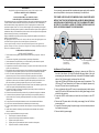
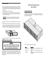
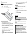
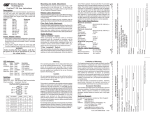
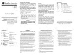
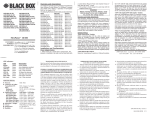
Omnitron Systems Technology, Inc. Hot Attachment of Power Supplies: 1. Unpack the power supply carefully. Inspect for any damages. If any damage is observed, do not use the power supply and call (949) 250-6510 to report the damage immediately and request a replacement unit. 2. Attach the power supply to the chassis and reconnect the 48VDC power source to the FlexPoint power supply. 3. Locate the 48VDC circuit breaker and switch the circuit breaker to the ON position. 4. Turn the FlexPoint Chassis power supply ON. 5. Observe the LED in the front of the chassis indicating that the power has been restored. JULY 2001 LMC200A-2PS-DC LMC200A-DC PSFP20-DC SPECIFICATION Indicators: Power ON: LED (2), Yellow, power applied Dimensions / Weight: W:19.0"xD:7.0"xH:3.5" / 9 lb. Power: 48VDC / 3.0 Amps (for model 4386) 2ea. 48VDC / 3.0 Amps (for model 4385) Environmental: Temperature: 0 to 40 degrees C Humidity: 0-90% (non-condensing) FlexPointTM Powered Chassis 48V Power Redundant 14 Module Chassis User’s Manual ©Copyright 1999-2001. Black Box Corporation. All rights reserved. 1000 Park Drive z Lawrence, PA 15055-1018 z 724-746-5500 z Fax 724-746-0746 CUSTOMER SUPPORT INFORMATION Order toll-free in the U.S.: Call 877-877-BBOX (outside U.S. call 724-746-5500) FREE technical support 24 hours a day, 7 days a week; Call 724-746-5500 or fax 724-746-0746 Mailing address: Black Box Corporation, 1000 Park Drive, Lawrence, PA 15055-1018 Web site: www.blackbox.com z E-mail: [email protected] 2 TRADEMARKS All applied-for and registered trademarks are the property of their respective owners. FEDERAL COMMUNICATIONS COMMISSION AND CANADIAN DEPARTMENT OF COMMUNICATIONS RADIO FREQUENCY INTERFERENCE STATEMENTS This equipment generates, uses, and can radiate radio frequency energy and if not installed and used properly, that is, in strict accordance with the manufacturer’s instructions, may cause interference to radio communication. It has been tested and found to comply with the limits for a Class A computing device in accordance with the specifications in subpart J of Part 15 of FCC rules, which are designed to provide reasonable protection against such interference when the equipment is operated in a commercial environment. Operation of this equipment in a residential area is likely to be cause interference, in which case the user at his own expense will be required to take whatever measures may be necessary to correct the interference. Changes or modifications not expressly approved by the party responsible for compliance could void the user’s authority to operate the equipment. This digital apparatus does not exceed the Class A limits for radio noise emission from digital apparatus set out in the Radio Interference Regulation of the Canadian Department of Communications. Le présent appareil numérique n’émet pas de bruits radioélectriques dépassant les limites applicables aux appareils numéirques de las classe A prescrites dans le Règlement sur le brouillage radioélectrique publié par le ministère des Communications du Canada. NORMAS OFICIALES MEXICANAS (NOM) ELECTRICAL SAFETY STATEMENT 1. Todas las instrucciones de seguridad y operación deberán ser leídas antes de que el aparato eléctrico sea operado. 2. Las instrucciones de seguridad y operación deberán ser guardadas para referencia futura. 3. Todas las advertencias en el aparato eléctrico y en sus instrucciones de operación deben ser respetadas. 4. Todas las instrucciones de operación y uso deben ser seguidas. 5. El aparato eléctrico no deberá ser usado cerca del agua—por ejemplo, cerca de la tina de baño, lavabo, sótano mojado o cerca de una alberca, etc. 6. El aparato eléctrico debe ser usado únicamente con carritos o pedelstales que sean recomendados por el fabricante. 7. El aparato eléctrico debe ser montado a la pared o al techo sólo como sea recomendado por el fabricante. 8. Servicio—El usuario no debe intentar dar servicio al equipo eléctrico más allá a lo descrito en las instrucciones de operación. Todo otro servicio deberá ser referido a personal de servicio calificado. 9. El aparato eléctrico debe ser situado de tal manera que su posición no interfiera su uso. La colocación del aparato eléctrico sobre una cama, sofá, alfombra or superficie similar puede bloquea la ventilación, no se debe colocar en libreros o gabinetes que impidan el flujo de aire por los orificios de ventilación. 10. El equipo eléctrico deber ser situado fuera del alcance de fuentes de calor como radiadores, registros de calor, estufas u ostros aparatos (incluyendo amplificadores) que producen calor. 11. El aparato eléctrico deberá ser connectado a una fuente de poder sólo del tipo descrito en el instructivo de operación, o como se indique en el aparato. 12. Precación debe ser tomada de tal manera que la tierra fisica y la polarización del equipo no sea eliminada. 13. Los cables de la fuente de poder deben ser guiados de tal manera que no sean pisados ni pellizcados por objetos colocados sobre o contra ellos, poniendo particular atención a los contactos y receptáculos donde salen del aparato. 14. El equipo eléctrico debe ser limpiado únicamente de acuerdo a las recomendaciones del fabricante. 15. En caso de existir, una antena externa deberá ser localizada lejos de las lineas de energia. 16. El cable de corriente deberá ser desconectado del cuando el equipo no sea usado por un largo periodo de tiempo. 17. Cuidado debe ser tomado de tal manera que objectos liquidos no sean derramados sobre la cubierta u orificios de ventilación. 18. Servicio por personal calificado deberá ser provisto cuando: A: El cable de poder o el contacto ha sido dañado; u B: Objectos han caído o líquido ha sido derramado dentro del aparato; o C: El aparato ha sido expuesto a la lluvia; o D: El aparato parece no operar normalmente o muestra un cambio en su desempeño; o E: El aparto ha sido tirado o su cubierta ha sido dañada. 7 It is very strongly recommended that a replacement power supply unit be installed as soon as possible in order to prevent overheating of the chassis unit. THE POWER SUPPLIES ARE HOT-SWAPPABLE AND CAN BE REPLACED WITHOUT SHUTTING THE NETWORK DOWN. HOWEVER, WHEN REMOVING AND REPLACING A POWER SUPPLY UNIT, THE FOLLOWING STEPS MUST BE STRICTLY FOLLOWED IN ORDER TO PREVENT SERIOUS INJURY OR DEATH, OR SERIOUS DAMAGE TO YOUR EQUIPMENT. DC Power Input 48 V DC 48 VDC Present ON OFF 5 VDC DC Power Input 48 V DC 48 VDC Present DC Power Input ON 48 V DC OFF 5 VDC 48 VDC Present ON OFF 5 VDC Power Supply Mounting Screws and guide pins. (2 each per unit) Power Supply Mounting Screws and guide pins. (2 each per unit) Hot Removal of Power Supplies: 1. Determine which power supply needs replacing by observing the LEDs in the front left of the chassis: the top LED indicates the power status of the right power supply (as observed from the front), the bottom LED indicates the power status of the left power supply (as observed from the front). Notice that LED being ON indicates that the power supply is operational. The LED being OFF may indicate that the DC power is not applied, please verify that your DC power source is providing power. 2. Once you determine that your DC source is connected properly, and the power supply LED is still not ON, determine which is the failing power supply unit and proceed to the next step. 3. Locate the 48VDC circuit breaker, and switch the circuit breaker to the OFF position. 4. Remove the DC power cables of the faulty power supply from the FlexPoint power supply unit. 5. Loosen the 2 screws securing the power supply to the main chassis (observe the illustration on page 7). 6. Remove the faulty power supply. 6 Omnitron Systems Technology, Inc.3 Cabling and Power-Up: 1. Insure that both FlexPoint Chassis power supply switches are in the OFF position. 2. Assure that the 48VDC circuit breaker can supply 3A of current per power supply. 3. Locate the 48VDC circuit breaker, and switch the 48VDC circuit breaker to the OFF position. 4. Cut the power cable to the length required. 5. Strip approximately 3/8 of an inch of insulation from the power cable wires. 6. Connect the power cables to the FlexPoint Chassis by fastening the stripped ends to the 48VDC connector. FlexPointTM Powered Chassis User’s Manual GENERAL DESCRIPTION The FlexPointTM Powered Chassis is a chassis capable of holding up to 14 FlexPointTM media converter modules. It is equipped with two power supplies in a power-redundant configuration. WARNING: Note the wire colors used for making the positive, negative and ground connections. Use the same color assignment for the connection at the circuit breaker. 7. Connect the power cable to the circuit breaker and switch the circuit breaker ON. 8. Turn both FlexPoint Chassis power supply switches on and check the power LED’s on the front panel of the powered chassis. The two LED’s should be ON. 9. Attach the L shaped tabs to the FlexPoint media converter units to be inserted into the chassis, Secure the FlexPoint module using the enclosed screws. 10. Save the unused tabs in a safe place or secure them to the chassis’ unused Slots. POWER SUPPLY REPLACEMENT WARNING! NEVER ATTEMPT TO OPEN OR SERVICE THE POWER SUPPLY UNIT. OPENING THE POWER SUPPLY UNIT MAY CAUSE SERIOUS INJURY OR DEATH. The Powered Chassis is intended to be used with two power supplies in a powerredundant operation. A failure of a single supply should not disturb the operation of the chassis unit. However, certain power supply failures may cause a secondary failure to the associated fan and cause undesired overheating of the chassis unit. This User’s Manual describes the following models: Model LMC200A-2PS-DC LMC200A-DC PSFP20-DC Description Powered Chassis, rack-mountable chassis, 2 power supplies Powered Chassis, rack-mountable chassis, 1 power supply Power supply unit for models LMC200A-2PS-DC and LMC200A-DC 4 5 CONTROLS AND INDICATORS LEDs Display: The Powered Chassis features two LEDs on the left front of the chassis, these LEDs display the status of the two power supplies. Function Top LED Bottom LED Color/State Yellow / ON Yellow / ON Description Power OK in right power supply Power OK in left power supply Note: Left/right direction as viewed from the front of the chassis. 8. Wiring methods used for the connection of the equipment to the primary power supply shall be in accordance with the National Electrical Code, ANSI/ NFPA 70, and the Canadian Electrical Code, Part I, C22.1. UNPACKING a. Visual Inspection: Inspect equipment in order to detect any physical damage. Any evidence of damage should be noted and reported immediately. INVENTORY Review contents, the following items should be included: (1) (2) (14) (14) (1) FlexPoint Powered Chassis unit. Power supplies (2 for model LMC200A-2PS-DC, 1 for model LMC200A-DC). L shape tabs. Screws User’s manual (this document). Please note any missing items or discrepancies and report them immediately. INSTALLATION WARNING: Only a DC power source that complies with safety extra low voltage (SLEV) requirements can be connected to the DC-input power supply. Tools and Equipment Required: SITE PREPARATION REQUIREMENTS 1. Power: Assure the 48VDC power can supply 3A of current. 2. The operating temperature of this equipment is 0-40 degrees C. If installed in a closed or multiunit rack assembly, the operating ambient temperature of the rack must not exceed the maximum rated 40 degrees C temperature. 3. Installation of the equipment should be such that the air flow in the front and back of the unit is not compromised or restricted. 4. Never use this equipment to carry any weight except its own, never use it as a shelf to support weight of other equipment. 5. Installing this equipment into a rack in such a way as to make it unstable may cause injury or death. Always make sure that the rack you are installing this equipment into is properly secure, stable, balanced and designed to carry the weight and weight distribution of this equipment. 6. When rack-mounting this equipment, the rack should be appropriately earth-grounded. 7. This equipment requires 48 VDC / 3.0 Amps per power supply. Appropriate overloading protection should be provided on all DC power source outlets utilized. Flat-head screwdriver (not supplied) Wire cutter/stripper (not supplied) Three-conductor 14 AWG copper power cable (recommended; not supplied) Preparation: Assure that the FlexPoint Chassis is physically installed in accordance with the Site Preparation Requirements outlined earlier in this document. WARNING REGARDING EARTHING GROUND: a) This equipment shall be connected to the DC supply system earthing electrode conductor or to a bonding jumper from an earthing terminal bar or bus to which the DC supply system earthing electrode is connected. b) This equipment shall be located in the same immediate area (such as, adjacent cabinets) as any other equipment that has a connection between the earthed conductor of the same DC supply circuit and the earthing conductor, and also the point of earthing of the DC system. The DC system shall not be earthed elswere. c) The DC supply source is to be located within the same premises as this equipment. d) There shall be no switching or disconnecting devices in the earthed circuit conductor between the DC source and the earthing electrode conductor.