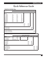
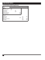
1
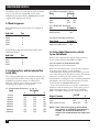
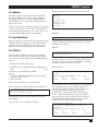
JULY 1999
SW590A-R2
SW590AE-R2
SW591C
Code Operated Switch II
4-Port Expansion Board
-II
S
O
C
LO 0
TATUS
LINK S
7 PWR
4 5 6
1 2 3
RESET
CUSTOMER
SUPPORT
INFORMATION
Order toll-free in the U.S. 24 hours, 7 A.M. Monday to midnight Friday: 877-877-BBOX
FREE technical support, 24 hours a day, 7 days a week: Call 724-746-5500 or fax 724-746-0746
Mail order: Black Box Corporation, 1000 Park Drive, Lawrence, PA 15055-1018
Web site: www.blackbox.com • E-mail: [email protected]
CODE OPERATED SWITCH II
FEDERAL COMMUNICATIONS COMMISSION
AND
INDUSTRY CANADA
RADIO FREQUENCY INTERFERENCE STATEMENTS
This equipment generates, uses, and can radiate radio frequency energy and if not installed and used properly, that is,
in strict accordance with the manufacturer’s instructions, may cause interference to radio communication. It has been
tested and found to comply with the limits for a Class A computing device in accordance with the specifications in
Subpart J of Part 15 of FCC rules, which are designed to provide reasonable protection against such interference when
the equipment is operated in a commercial environment. Operation of this equipment in a residential area is likely to
cause interference, in which case the user at his own expense will be required to take whatever measures may be
necessary to correct the interference.
Changes or modifications not expressly approved by the party responsible for compliance could void the user’s
authority to operate the equipment.
This digital apparatus does not exceed the Class A limits for radio noise emission from digital apparatus set out in the Radio
Interference Regulation of Industry Canadian.
Le présent appareil numérique n’émet pas de bruits radioélectriques dépassant les limites applicables aux appareils numériques
de classe A prescrites dans le Règlement sur le brouillage radioélectrique publié par Industrie Canada.
INSTRUCCIONES DE SEGURIDAD (Normas Oficiales Mexicanas Electrical Safety Statement)
1. Todas las instrucciones de seguridad y operación
deberán ser leídas antes de que el aparato eléctrico
sea operado.
12. Precaución debe ser tomada de tal manera que la
tierra fisica y la polarización del equipo no sea
eliminada.
2. Las instrucciones de seguridad y operación deberán
ser guardadas para referencia futura.
3. Todas las advertencias en el aparato eléctrico y en
sus instrucciones de operación deben ser respetadas.
13. Los cables de la fuente de poder deben ser guiados
de tal manera que no sean pisados ni pellizcados por
objetos colocados sobre o contra ellos, poniendo
particular atención a los contactos y receptáculos
donde salen del aparato.
4. Todas las instrucciones de operación y uso deben ser
seguidas.
14. El equipo eléctrico debe ser limpiado únicamente
de acuerdo a las recomendaciones del fabricante.
5. El aparato eléctrico no deberá ser usado cerca del
agua—por ejemplo, cerca de la tina de baño, lavabo,
sótano mojado o cerca de una alberca, etc..
15. En caso de existir, una antena externa deberá ser
localizada lejos de las lineas de energia.
6. El aparato eléctrico debe ser usado únicamente con
carritos o pedestales que sean recomendados por el
fabricante.
7. El aparato eléctrico debe ser montado a la pared o al
techo sólo como sea recomendado por el fabricante.
8. Servicio—El usuario no debe intentar dar servicio
al equipo eléctrico más allá a lo descrito en las
instrucciones de operación. Todo otro servicio
deberá ser referido a personal de servicio calificado.
9. El aparato eléctrico debe ser situado de tal manera
que su posición no interfiera su uso. La colocación
del aparato eléctrico sobre una cama, sofá, alfombra
o superficie similar puede bloquea la ventilación, no
se debe colocar en libreros o gabinetes que impidan
el flujo de aire por los orificios de ventilación.
10. El equipo eléctrico deber ser situado fuera del
alcance de fuentes de calor como radiadores,
registros de calor, estufas u otros aparatos
(incluyendo amplificadores) que producen calor.
11. El aparato eléctrico deberá ser connectado
a una fuente de poder sólo del tipo descrito
en el instructivo de operación, o como se indique
en el aparato.
16. El cable de corriente deberá ser desconectado del
cuando el equipo no sea usado por un largo periodo
de tiempo.
17. Cuidado debe ser tomado de tal manera que
objectos liquidos no sean derramados sobre la
cubierta u orificios de ventilación.
18. Servicio por personal calificado deberá ser provisto
cuando:
A: El cable de poder o el contacto ha sido dañado;
u
B: Objectos han caído o líquido ha sido derramado
dentro del aparato; o
C: El aparato ha sido expuesto a la lluvia; o
D: El aparato parece no operar normalmente o
muestra un cambio en su desempeño; o
E: El aparato ha sido tirado o su cubierta ha sido
dañada.
Contents
Contents
Chapter
Page
1 Specifications .............................................................................................................4
2 Introduction ...............................................................................................................5
3 Installation..................................................................................................................6
3.1 Introduction ..............................................................................................................6
3.2 Setting the DIP Switches ..........................................................................................6
3.3 Functions and Arrangements of the Switch Banks ................................................7
3.4 Bank Assignments .....................................................................................................8
3.5 Configuring Ports with the Individual Port Switch Banks.....................................8
3.6 Setting Global Characteristics with the System Switch Banks ...............................8
3.6.1 Functions fo Switch Bank SWF ......................................................................8
3.6.2 Setting the Arming Character with SWG....................................................10
3.7 Setting Global Characteristics with the Individual Banks ...................................16
3.8 Configuring Ports for DTE or DCE.......................................................................16
3.9 Connecting and Powering-Up the COS-II............................................................17
4 Operation
4.1 Introduction .......................................................................................................18
4.2 Creating a Link ..................................................................................................18
4.3 Signaling a Lock.................................................................................................18
4.4 Text Mode...........................................................................................................18
4.5 Graphics Mode...................................................................................................18
4.6 Indicators............................................................................................................19
4.7 Front-Panel Button ............................................................................................19
4.8 Self-Tests .............................................................................................................19
Quick Reference Guide ..............................................................................................21
If you’re already familiar with the Code Operated Switch II, and you just need to know how
to configure the DIP switches, you can turn to the Quick Reference Guide on page 21.
This product is CE certified. This certificate indicates that the product is suitable for
use in commercial and light industrial environments as defined in EN 50081-1:1992.
NOTE
Shielded interface cables must be used with this product. Call Technical Support
at 724-746-5500 for guidance in choosing cables.
3
CODE OPERATED SWITCH II
1. Specifications
Interface — RS-232 asynchronous (each port individually selectable for DTE or DCE)
Connectors — Switch: (5) DB25S female; Switch with Expansion Board: (9) DB25S female
Pins Supported — 1-8, 20, 22
Speed — 110 to 19,200 bps (selectable by port)
Memory — 8K buffer
Enclosure — Steel
Operating Temperature — 32°F to 113°F (0° to 45°C)
Humidity — 0 to 95% relative humidity
Mean Time Between Failures — Standard Switch: 20,000 hours; Switch with Expansion Board: 16,000 hours
Indicators —LEDs: 1 Power, 1 Lockout, 8 Port-Connected
Power — 115 VAC (230-VAC version available)
Size — 2.3"H x 12.2"W x 11"D (5.8 x 31 x 27.9 cm)
Weight — Switch: 7.5 lb. (3.4 kg); Expansion Board: 0.6 lb. (0.3 kg); Wallmount power supply: 2.1 lb. (1 kg)
4
CHAPTER 2: Introduction
2. Introduction
The Code Operated Switch II (COS II) makes
code-operated switching possible for diverse
combinations of serial devices. As it switches, the
COS II also reconciles differences in word size,
speed, flow control, and parity for up to four
devices. An Expansion Board, available separately,
doubles the maximum number of devices, to eight.
Configuration is port-independent: You may set
different speeds, word sizes, parities, and flow-control
requirements for each port. The 8K buffer handles
speed conversions from 110 bps to 19,200 bps. DTE
and DCE are also independently determined for
every port.
A control sequence manages the switching for the
COS II. The COS II will accept the sequence from
any port—the master port, which will ordinarily
have a PC or terminal connected to it, or any of
the four (or eight) slave ports.
A special graphics timeout lets you send graphics
files through the Switch without the chance of
accidental switching. In graphics mode, the COS II
recognizes the appearance of the control code only
when the code characters are preceded by a pause
of a specified length. The COS II treats all other
occurrences of the control code as data—they are
passed along to the slave device with the rest of the
characters in the file.
Any office, lab, or shop with a variety of serial
devices will benefit from a COS II. Use it in a typical
multiprinter office, or to transfer files between
computers. You could also set up the COS II as the
link between a single PC and a mixture of highand low-speed remote data lines. The COS II will
pass your high-speed—9600-bps—data without
interference, while the internal buffer of the COS
will downshift PC data for the slower modems.
5
CODE OPERATED SWITCH II
3. Installation
switches for the internal options of the COS II.
Then, you’ll specify DTE or DCE for each port by
setting shunt jumpers. Finally, you’ll cable the
Switch to your devices and connect power to the
COS II.
3.1. Introduction
In addition to this manual, your Switch package
should contain one standard switch unit and a
wallmounted power supply. After you’ve unpacked
the Switch, take a few minutes to look through this
manual. You will need a screwdriver large enough to
remove the case screws, and a small screwdriver or
other edged tool for setting DIP switches. Also, you
might want to refer to the manuals of the devices
you plan to connect to the COS-II.
3.2. Setting the DIP switches
In order to set the DIP switches, you’ll need to open
the case of the COS-II. There are several screws on
each side. Remove them, and lift the case lid from
the body of the COS-II. The board layout of your
unit should match the diagram shown below
(Fig.1).
Installing the COS-II is a simple, three-step task
that should take no more than an hour to
complete. First, you’ll configure all of the DIP
(BACK)
PORT 4
PORT 3
PORT 2
PORT 1
PORT 0
DTE
DTE
DTE
DTE
DTE
DCE
DCE
DCE
DCE
DCE
W1
R1
J7
J1
U20
U23
RESET BUTTON
VR1
S1
INDIVIDUAL PORT SWITCHES
SYSTEM SWITCHES
(SWF & SWG)
SW
G
PORT 4
PORT 3
PORT 2
PORT 1
PORT 0
SW
E
SW
D
SW
C
SW
B
SW
A
SW
F
OFF
OFF
OFF
OFF
OFF
OFF
OFF
STATUS INDICATORS
CH0 CH1 CH2 CH3 CH4 CH5 CH6 CH7 CH8
(FRONT)
Fig. 3-1. Board Layout for the COS-II.
6
PWR
CHAPTER 3: Installation
The board layout for the Four-Port Expansion
Board is shown on this page (Fig. 2). If you have
ordered one, check your Board to make sure it
matches.
NOTE: Every time you change the DIP switch
settings, you must press the reset button
located on the front panel of the switch, or
unplug the power supply. The COS-II will not
process any data during a reset.
A note on charts: you’ll find all the charts printed in
this chapter duplicated either in the Appendix or in
the Quick Reference Guide.
3.3 Functions and Arrangement of the Switch
Banks
On the standard board there are seven banks of DIP
switches, of which five control the characteristics of
the individual ports (SWA through SWE). The
remaining two banks (SWF, SWG) control options
that affect the entire system. The Four-Port
Expansion Board adds individual port banks SWH
through SWK.
A note on terminology: This manual will use the
following system to designate individual switches
within each switch bank. The bank label will be
given first, followed by a hyphen and then the
number of the DIP switch. “SWA-6” refers to the
sixth DIP switch of Switch Bank A. Also, the words
“ON” and “OFF” are used in the switch charts, but
your banks may have the words “CLOSED” and
“OPEN” printed instead. “CLOSED” is equivalent
to “ON,” and “OPEN” is equivalent to “OFF.”
You’ll set the following options with Switch Banks
SWA through SWE (the individual port banks):
• Data rates, from 110 to 19,200 bps
• Parity—even, odd, or no parity
• Word sizes —7 or 8 bits
• Flow control by hardware (DTR/CTS) or
software (X-ON/X-OFF).
Section 3.4 covers these banks in more detail.
The two banks SWF and SWG (system banks)
regulate:
• Responsibility for the Link Command (from
master or slave port)
• Automatic timeout period
• Length of pause in Graphics Mode
• Lead Pass-Through
• Arming character
(BACK)
PORT 8
PORT 7
PORT 6
PORT 5
DTE
DTE
DTE
DTE
DCE
DCE
DCE
DCE
INDIVIDUAL PORT SWITCHES
(PORTS 5 THRU 8)
PORT 8
OFF
PORT 7
OFF
SWK
PORT 6
OFF
SWJ
PORT 5
OFF
SWI
SWH
(FRONT)
Fig. 3-2. Layout of the 4-Port Expansion Board.
7
CODE OPERATED SWITCH II
In addition, there are some system characteristics
that are set with the eighth DIP switch of the
individual port switch banks. Sections 3.6 and 3.7
explain these functions in depth.
3.4 Bank Assignments
SWA
SWB
SWC
SWD
SWE
SWH
SWI
SWJ
SWK
Port
Master Device Port
0
1
2
3
OFF
ON
OFF
ON
OFF
OFF
Set Switch 6
OFF
ON
3.5.4 FLOW CONTROL (SWITCH 7)
Flow Control
Hardware (DTR/CTS)
Software (X-ON/X-OFF)
Set Switch 7
ON
OFF
3.6 Setting Global Characteristics with the
System Switch Banks
Port
Refer to the explanations and the charts below to
set the system switch banks SWF and SWG.
4
5
6
7
To set the switch banks, use a small screwdriver or
other small object with a clean edge or point. The
individual port switch banks are identical in
function, and the set of charts provided on the
following pages applies to all of them.
3.5.1 PORT SPEED (SWITCHES 1, 2, AND 3)
Speed
1
8
Even
Odd
None
7 bits per word
8 bits per word
3.5 Configuring Ports with the Individual Port
Switch Banks
110 bps
300 bps
600 bps
1200 bps
2400 bps
4800 bps
9600 bps
19200 bps
Set Switch
4
5
Size
The Four-Port Expansion Board provides these
additional banks:
Bank Label
Parity
3.5.3 WORD SIZE (SWITCH 6)
The individual port switch banks are assigned as
follows:
Bank Label
3.5.2 PARITY (SWITCHES 4 AND 5)
ON
OFF
ON
OFF
ON
OFF
ON
OFF
Set Switches
2
ON
ON
OFF
OFF
ON
ON
OFF
OFF
3
ON
ON
ON
ON
OFF
OFF
OFF
OFF
3.6.1 FUNCTIONS OF SWITCH BANK SWF
Responsibility for the Link Command
When the COS II receives a control code sequence
from the proper device, it will establish a
communications link between the master port and
one of the slave ports. If it then receives the lockout
character—a character with a value of 38 in
hexadecimal—it will ignore the remaining unlinked
subordinate ports. For more information on links
and lockouts, see Sections 4.2 and 4.3.
You can set the Switch to accept the command to
link from only the master port, only a slave port, or
from either the master or a slave port. Switches
SWF 1 and SWF 2 designate the origin of the link.
Origin of Command
Set SWF
1
2
master
slave
either master or slave
ON
OFF
ON or OFF
ON
ON
OFF
NOTE: If the slave ports are set up for hardware
flow control, or if DTR/CTS pass-through is
enabled, you should set the Switch to
accept a link command from the master port
only.
CHAPTER 3: Installation
Automatic Timeout
Master Slave
Leads Passed
The COS II times the intervals between the
reception of each character and the next. You may
instruct it to return to an unlinked state after
intervals of 2.5, 5, or 10 minutes, or you may disable
this automatic timeout feature. SWF 5 and SWF 6
control this feature.
DTE
DTE
DTE
DCE
DCE
DTE
DCE
DCE
Master CTS to slave DTR
Slave CTS to master DTR
Master CTS to slave CTS
Slave DTR to master DTR
Master DTR to slave DTR
Slave CTS to master CTS
Master DTR to slave CTS
Slave DTR to master CTS
Timeout Setting
Set SWF5
6
2.5 minutes
5 minutes
10 minutes
Disabled
ON
OFF
ON
OFF
ON
ON
OFF
OFF
Graphics Pause
These switch settings are followed only when the
COS II has been set previously for Graphics Mode
(for an explanation, see Section 4.5). They
determine the amount of time that must pass
before the COS II recognizes a control code
sequence.
By providing for this pause, it is possible to send
graphics files through the unit with no risk that it
will switch accidentally when it encounters a control
code sequence, or its binary equivalent. SWF 7 and
SWF 8 determine the length of the pause.
CTS-to-DTR Pass-Through Mode
To Set A Pause of
50 milliseconds
100 milliseconds
500 milliseconds
1.5 seconds
Set SWF
7
8
ON
OFF
ON
OFF
ON
ON
OFF
OFF
If you choose CTS-to-DTR Pass-Through, CTS
(Pin 5) and DTR (Pin 20) are passed straight
through the Switch. The next table shows how the
DTE or DCE setting of the port affects the passthrough option:
NOTE: If the internal buffer fills, the appropriate
control lead (DTR or CTS) will be dropped to
prevent data loss.
If you select Normal Operation, DTR (Pin 20) and
CTS (Pin 5) are used strictly for buffer control.
They are not passed straight through the Switch.
DCD-to-RTS Pass-Through Mode
To Set This Mode
Set SWC 8
CTS-to-DTR Pass-Through
Normal Operation
ON
OFF
If you select DCD-to-RTS Pass-Through, DCD
(Pin 8) and RTS (Pin 4) are passed straight through
the Switch. The next table shows how the DTE or
DCE setting of the port affects the pass-through
option:
If you select Normal Operation, DCD and RTS are
Master Slave
Leads Passed
DTE
DTE
DTE
DCE
DCE
DTE
DCE
DCE
Master DCD to slave RTS
Slave DCD to master RTS
Master DCD to slave DCD
Slave RTS to master RTS
Master RTS to slave RTS
Slave DCD to master DCD
Master RTS to slave DCD
Slave RTS to master DCD
always asserted. They are not passed through the
Switch.
To Set This Mode
Set SWF 3
DCD-to-RTS Pass-Through
Normal Operation
ON
OFF
9
CODE OPERATED SWITCH II
3.6.2 SETTING THE ARMING CHARACTER WITH SWG
Switch Bank SWG supplies a portion of the control-code sequence, the sequence that activates the Switch.
The arming character, the ASCII code that alerts the COS-II to an upcoming switch action, is set with SWG.
The settings are given in the chart below. For a more detailed explanation of control codes, see Section 4.2.
A note on abbreviations: LSB stands for least significant bit, MSB for most significant bit.
ARMING CHARACTER SWITCH POSITIONS
ASCII
NUL
SOH
STX
ETX
EOT
ENQ
ACK
BEL
BS
HT
LF
VT
FF
CR
SO
SI
DLE
DC1
DC2
DC3
DC4
NAK
SYN
ETB
CAN
EM
SUB
ESC
FS
GS
RS
US
SP
!
"
#
$
%
&
10
CTRL
@
A
B
C
D
E
F
G
H
I
J
K
L
M
N
O
P
Q
R
S
T
U
V
W
X
Y
Z
[
\
]
^
_
HEX DECIMAL
00
0
01
1
02
2
03
3
04
4
05
5
06
6
07
7
08
8
09
9
0A
10
0B
11
0C
12
0D
13
0E
14
0F
15
10
16
11
17
12
18
13
19
14
20
15
21
16
22
17
23
18
24
19
25
1A
26
1B
27
1C
28
1D
29
1E
30
1F
31
20
32
21
33
22
34
23
35
24
36
25
37
26
38
LSB
1
OFF
ON
OFF
ON
OFF
ON
OFF
ON
OFF
ON
OFF
ON
OFF
ON
OFF
ON
OFF
ON
OFF
ON
OFF
ON
OFF
ON
OFF
ON
OFF
ON
OFF
ON
OFF
ON
OFF
ON
OFF
ON
OFF
ON
OFF
2
OFF
OFF
ON
ON
OFF
OFF
ON
ON
OFF
OFF
ON
ON
OFF
OFF
ON
ON
OFF
OFF
ON
ON
OFF
OFF
ON
ON
OFF
OFF
ON
ON
OFF
OFF
ON
ON
OFF
OFF
ON
ON
OFF
OFF
ON
3
OFF
OFF
OFF
OFF
ON
ON
ON
ON
OFF
OFF
OFF
OFF
ON
ON
ON
ON
OFF
OFF
OFF
OFF
ON
ON
ON
ON
OFF
OFF
OFF
OFF
ON
ON
ON
ON
OFF
OFF
OFF
OFF
ON
ON
ON
4
OFF
OFF
OFF
OFF
OFF
OFF
OFF
OFF
ON
ON
ON
ON
ON
ON
ON
ON
OFF
OFF
OFF
OFF
OFF
OFF
OFF
OFF
ON
ON
ON
ON
ON
ON
ON
ON
OFF
OFF
OFF
OFF
OFF
OFF
OFF
5
OFF
OFF
OFF
OFF
OFF
OFF
OFF
OFF
OFF
OFF
OFF
OFF
OFF
OFF
OFF
OFF
ON
ON
ON
ON
ON
ON
ON
ON
ON
ON
ON
ON
ON
ON
ON
ON
OFF
OFF
OFF
OFF
OFF
OFF
OFF
6
OFF
OFF
OFF
OFF
OFF
OFF
OFF
OFF
OFF
OFF
OFF
OFF
OFF
OFF
OFF
OFF
OFF
OFF
OFF
OFF
OFF
OFF
OFF
OFF
OFF
OFF
OFF
OFF
OFF
OFF
OFF
OFF
ON
ON
ON
ON
ON
ON
ON
7
OFF
OFF
OFF
OFF
OFF
OFF
OFF
OFF
OFF
OFF
OFF
OFF
OFF
OFF
OFF
OFF
OFF
OFF
OFF
OFF
OFF
OFF
OFF
OFF
OFF
OFF
OFF
OFF
OFF
OFF
OFF
OFF
OFF
OFF
OFF
OFF
OFF
OFF
OFF
MSB
8
OFF
OFF
OFF
OFF
OFF
OFF
OFF
OFF
OFF
OFF
OFF
OFF
OFF
OFF
OFF
OFF
OFF
OFF
OFF
OFF
OFF
OFF
OFF
OFF
OFF
OFF
OFF
OFF
OFF
OFF
OFF
OFF
OFF
OFF
OFF
OFF
OFF
OFF
OFF
CHAPTER 3: Installation
ARMING CHARACTER SWITCH POSITIONS
ASCII
’
(
)
*
+
,
.
/
0
1
2
3
4
5
6
7
8
9
:
;
<
=
>
?
@
A
B
C
D
E
F
G
H
I
J
K
L
M
N
O
P
Q
R
CTRL
HEX DECIMAL
27
39
28
40
29
41
2A
42
2B
43
2C
44
2D
45
2E
46
2F
47
30
48
31
49
32
50
33
51
34
52
35
53
36
54
37
55
38
56
39
57
3A
58
3B
59
3C
60
3D
61
3E
62
3F
63
40
64
41
65
42
66
43
67
44
68
45
69
46
70
47
71
48
72
49
73
4A
74
4B
75
4C
76
4D
77
4E
78
4F
79
50
80
51
81
52
82
LSB
1
ON
OFF
ON
OFF
ON
OFF
ON
OFF
ON
OFF
ON
OFF
ON
OFF
ON
OFF
ON
OFF
ON
OFF
ON
OFF
ON
OFF
ON
OFF
ON
OFF
ON
OFF
ON
OFF
ON
OFF
ON
OFF
ON
OFF
ON
OFF
ON
OFF
ON
OFF
2
ON
OFF
OFF
ON
ON
OFF
OFF
ON
ON
OFF
OFF
ON
ON
OFF
OFF
ON
ON
OFF
OFF
ON
ON
OFF
OFF
ON
ON
OFF
OFF
ON
ON
OFF
OFF
ON
ON
OFF
OFF
ON
ON
OFF
OFF
ON
ON
OFF
OFF
ON
3
ON
OFF
OFF
OFF
OFF
ON
ON
ON
ON
OFF
OFF
OFF
OFF
ON
ON
ON
ON
OFF
OFF
OFF
OFF
ON
ON
ON
ON
OFF
OFF
OFF
OFF
ON
ON
ON
ON
OFF
OFF
OFF
OFF
ON
ON
ON
ON
OFF
OFF
OFF
4
OFF
ON
ON
ON
ON
ON
ON
ON
ON
OFF
OFF
OFF
OFF
OFF
OFF
OFF
OFF
ON
ON
ON
ON
ON
ON
ON
ON
OFF
OFF
OFF
OFF
OFF
OFF
OFF
OFF
ON
ON
ON
ON
ON
ON
ON
ON
OFF
OFF
OFF
5
OFF
OFF
OFF
OFF
OFF
OFF
OFF
OFF
OFF
ON
ON
ON
ON
ON
ON
ON
ON
ON
ON
ON
ON
ON
ON
ON
ON
OFF
OFF
OFF
OFF
OFF
OFF
OFF
OFF
OFF
OFF
OFF
OFF
OFF
OFF
OFF
OFF
ON
ON
ON
6
ON
ON
ON
ON
ON
ON
ON
ON
ON
ON
ON
ON
ON
ON
ON
ON
ON
ON
ON
ON
ON
ON
ON
ON
ON
OFF
OFF
OFF
OFF
OFF
OFF
OFF
OFF
OFF
OFF
OFF
OFF
OFF
OFF
OFF
OFF
OFF
OFF
OFF
7
OFF
OFF
OFF
OFF
OFF
OFF
OFF
OFF
OFF
OFF
OFF
OFF
OFF
OFF
OFF
OFF
OFF
OFF
OFF
OFF
OFF
OFF
OFF
OFF
OFF
ON
ON
ON
ON
ON
ON
ON
ON
ON
ON
ON
ON
ON
ON
ON
ON
ON
ON
ON
MSB
8
OFF
OFF
OFF
OFF
OFF
OFF
OFF
OFF
OFF
OFF
OFF
OFF
OFF
OFF
OFF
OFF
OFF
OFF
OFF
OFF
OFF
OFF
OFF
OFF
OFF
OFF
OFF
OFF
OFF
OFF
OFF
OFF
OFF
OFF
OFF
OFF
OFF
OFF
OFF
OFF
OFF
OFF
OFF
OFF
11
CODE OPERATED SWITCH II
ARMING CHARACTER SWITCH POSITIONS
ASCII
S
T
U
V
W
X
Y
Z
[
\
]
^
_
`
a
b
c
d
e
f
g
h
i
j
k
l
m
n
o
p
q
r
s
t
u
v
w
x
y
z
{
}
~
DEL
12
CTRL
HEX DECIMAL
53
83
54
84
55
85
56
86
57
87
58
88
59
89
5A
90
5B
91
5C
92
5D
93
5E
94
5F
95
60
96
61
97
62
98
63
99
64
100
65
101
66
102
67
103
68
104
69
105
6A
106
6B
107
6C
108
6D
109
6E
110
6F
111
70
112
71
113
72
114
73
115
74
116
75
117
76
118
77
119
78
120
79
121
7A
122
7B
123
7C
124
7D
125
7E
126
7F
127
LSB
1
ON
OFF
ON
OFF
ON
OFF
ON
OFF
ON
OFF
ON
OFF
ON
OFF
ON
OFF
ON
OFF
ON
OFF
ON
OFF
ON
OFF
ON
OFF
ON
OFF
ON
OFF
ON
OFF
ON
OFF
ON
OFF
ON
OFF
ON
OFF
ON
OFF
ON
OFF
ON
2
ON
OFF
OFF
ON
ON
OFF
OFF
ON
ON
OFF
OFF
ON
ON
OFF
OFF
ON
ON
OFF
OFF
ON
ON
OFF
OFF
ON
ON
OFF
OFF
ON
ON
OFF
OFF
ON
ON
OFF
OFF
ON
ON
OFF
OFF
ON
ON
OFF
OFF
ON
ON
3
OFF
ON
ON
ON
ON
OFF
OFF
OFF
OFF
ON
ON
ON
ON
OFF
OFF
OFF
OFF
ON
ON
ON
ON
OFF
OFF
OFF
OFF
ON
ON
ON
ON
OFF
OFF
OFF
OFF
ON
ON
ON
ON
OFF
OFF
OFF
OFF
ON
ON
ON
ON
4
OFF
OFF
OFF
OFF
OFF
ON
ON
ON
ON
ON
ON
ON
ON
OFF
OFF
OFF
OFF
OFF
OFF
OFF
OFF
ON
ON
ON
ON
ON
ON
ON
ON
OFF
OFF
OFF
OFF
OFF
OFF
OFF
OFF
ON
ON
ON
ON
ON
ON
ON
ON
5
ON
ON
ON
ON
ON
ON
ON
ON
ON
ON
ON
ON
ON
OFF
OFF
OFF
OFF
OFF
OFF
OFF
OFF
OFF
OFF
OFF
OFF
OFF
OFF
OFF
OFF
OFF
ON
ON
ON
ON
ON
ON
ON
ON
ON
ON
ON
ON
ON
ON
ON
6
OFF
OFF
OFF
OFF
OFF
OFF
OFF
OFF
OFF
OFF
OFF
OFF
OFF
ON
ON
ON
ON
ON
ON
ON
ON
ON
ON
ON
ON
ON
ON
ON
ON
ON
ON
ON
ON
ON
ON
ON
ON
ON
ON
ON
ON
ON
ON
ON
ON
7
ON
ON
ON
ON
ON
ON
ON
ON
ON
ON
ON
ON
ON
ON
ON
ON
ON
ON
ON
ON
ON
ON
ON
ON
ON
ON
ON
ON
ON
ON
ON
ON
ON
ON
ON
ON
ON
ON
ON
ON
ON
ON
ON
ON
ON
MSB
8
OFF
OFF
OFF
OFF
OFF
OFF
OFF
OFF
OFF
OFF
OFF
OFF
OFF
OFF
OFF
OFF
OFF
OFF
OFF
OFF
OFF
OFF
OFF
OFF
OFF
OFF
OFF
OFF
OFF
OFF
OFF
OFF
OFF
OFF
OFF
OFF
OFF
OFF
OFF
OFF
OFF
OFF
OFF
OFF
OFF
CHAPTER 3: Installation
ARMING CHARACTER SWITCH POSITIONS
ASCII
CTRL
HEX DECIMAL
80
128
81
129
82
130
83
131
84
132
85
133
86
134
87
135
88
136
89
137
8A
138
8B
139
8C
140
8D
141
8E
142
8F
143
90
144
91
145
92
146
93
147
94
148
95
149
96
150
97
151
98
152
99
153
9A
154
9B
155
9C
156
9D
157
9E
158
9F
159
A0
160
A1
161
A2
162
A3
163
A4
164
A5
165
A6
166
A7
167
A8
168
A9
169
AA
170
AB
171
AC
172
AD
173
LSB
1
OFF
ON
OFF
ON
OFF
ON
OFF
ON
OFF
ON
OFF
ON
OFF
ON
OFF
ON
OFF
ON
OFF
ON
OFF
ON
OFF
ON
OFF
ON
OFF
ON
OFF
ON
OFF
ON
OFF
ON
OFF
ON
OFF
ON
OFF
ON
OFF
ON
OFF
ON
OFF
ON
2
OFF
OFF
ON
ON
OFF
OFF
ON
ON
OFF
OFF
ON
ON
OFF
OFF
ON
ON
OFF
OFF
ON
ON
OFF
OFF
ON
ON
OFF
OFF
ON
ON
OFF
OFF
ON
ON
OFF
OFF
ON
ON
OFF
OFF
ON
ON
OFF
OFF
ON
ON
OFF
OFF
3
OFF
OFF
OFF
OFF
ON
ON
ON
ON
OFF
OFF
OFF
OFF
ON
ON
ON
ON
OFF
OFF
OFF
OFF
ON
ON
ON
ON
OFF
OFF
OFF
OFF
ON
ON
ON
ON
OFF
OFF
OFF
OFF
ON
ON
ON
ON
OFF
OFF
OFF
OFF
ON
ON
4
OFF
OFF
OFF
OFF
OFF
OFF
OFF
OFF
ON
ON
ON
ON
ON
ON
ON
ON
OFF
OFF
OFF
OFF
OFF
OFF
OFF
OFF
ON
ON
ON
ON
ON
ON
ON
ON
OFF
OFF
OFF
OFF
OFF
OFF
OFF
OFF
ON
ON
ON
ON
ON
ON
5
OFF
OFF
OFF
OFF
OFF
OFF
OFF
OFF
OFF
OFF
OFF
OFF
OFF
OFF
OFF
OFF
ON
ON
ON
ON
ON
ON
ON
ON
ON
ON
ON
ON
ON
ON
ON
ON
OFF
OFF
OFF
OFF
OFF
OFF
OFF
OFF
OFF
OFF
OFF
OFF
OFF
OFF
6
OFF
OFF
OFF
OFF
OFF
OFF
OFF
OFF
OFF
OFF
OFF
OFF
OFF
OFF
OFF
OFF
OFF
OFF
OFF
OFF
OFF
OFF
OFF
OFF
OFF
OFF
OFF
OFF
OFF
OFF
OFF
OFF
ON
ON
ON
ON
ON
ON
ON
ON
ON
ON
ON
ON
ON
ON
7
OFF
OFF
OFF
OFF
OFF
OFF
OFF
OFF
OFF
OFF
OFF
OFF
OFF
OFF
OFF
OFF
OFF
OFF
OFF
OFF
OFF
OFF
OFF
OFF
OFF
OFF
OFF
OFF
OFF
OFF
OFF
OFF
OFF
OFF
OFF
OFF
OFF
OFF
OFF
OFF
OFF
OFF
OFF
OFF
OFF
OFF
MSB
8
ON
ON
ON
ON
ON
ON
ON
ON
ON
ON
ON
ON
ON
ON
ON
ON
ON
ON
ON
ON
ON
ON
ON
ON
ON
ON
ON
ON
ON
ON
ON
ON
ON
ON
ON
ON
ON
ON
ON
ON
ON
ON
ON
ON
ON
ON
13
CODE OPERATED SWITCH II
ARMING CHARACTER SWITCH POSITIONS
ASCII
14
CTRL
HEX DECIMAL
AE
174
AF
175
B0
176
B1
177
B2
178
B3
179
B4
180
B5
181
B6
182
B7
183
B8
184
B9
185
BA
186
BB
187
BC
188
BD
189
BE
190
BF
191
C0
192
C1
193
C2
194
C3
195
C4
196
C5
197
C6
198
C7
199
C8
200
C9
201
CA
202
CB
203
CC
204
CD
205
CE
206
CF
207
D0
208
D1
209
D2
210
D3
211
D4
212
D5
213
D6
214
D7
215
D8
216
D9
217
DA
218
DB
219
DC
220
DD
221
DE
222
LSB
1
OFF
ON
OFF
ON
OFF
ON
OFF
ON
OFF
ON
OFF
ON
OFF
ON
OFF
ON
OFF
ON
OFF
ON
OFF
ON
OFF
ON
OFF
ON
OFF
ON
OFF
ON
OFF
ON
OFF
ON
OFF
ON
OFF
ON
OFF
ON
OFF
ON
OFF
ON
OFF
ON
OFF
ON
OFF
2
ON
ON
OFF
OFF
ON
ON
OFF
OFF
ON
ON
OFF
OFF
ON
ON
OFF
OFF
ON
ON
OFF
OFF
ON
ON
OFF
OFF
ON
ON
OFF
OFF
ON
ON
OFF
OFF
ON
ON
OFF
OFF
ON
ON
OFF
OFF
ON
ON
OFF
OFF
ON
ON
OFF
OFF
ON
3
ON
ON
OFF
OFF
OFF
OFF
ON
ON
ON
ON
OFF
OFF
OFF
OFF
ON
ON
ON
ON
OFF
OFF
OFF
OFF
ON
ON
ON
ON
OFF
OFF
OFF
OFF
ON
ON
ON
ON
OFF
OFF
OFF
OFF
ON
ON
ON
ON
OFF
OFF
OFF
OFF
ON
ON
ON
4
ON
ON
OFF
OFF
OFF
OFF
OFF
OFF
OFF
OFF
ON
ON
ON
ON
ON
ON
ON
ON
OFF
OFF
OFF
OFF
OFF
OFF
OFF
OFF
ON
ON
ON
ON
ON
ON
ON
ON
OFF
OFF
OFF
OFF
OFF
OFF
OFF
OFF
ON
ON
ON
ON
ON
ON
ON
5
OFF
OFF
ON
ON
ON
ON
ON
ON
ON
ON
ON
ON
ON
ON
ON
ON
ON
ON
OFF
OFF
OFF
OFF
OFF
OFF
OFF
OFF
OFF
OFF
OFF
OFF
OFF
OFF
OFF
OFF
ON
ON
ON
ON
ON
ON
ON
ON
ON
ON
ON
ON
ON
ON
ON
6
ON
ON
ON
ON
ON
ON
ON
ON
ON
ON
ON
ON
ON
ON
ON
ON
ON
ON
OFF
OFF
OFF
OFF
OFF
OFF
OFF
OFF
OFF
OFF
OFF
OFF
OFF
OFF
OFF
OFF
OFF
OFF
OFF
OFF
OFF
OFF
OFF
OFF
OFF
OFF
OFF
OFF
OFF
OFF
OFF
7
OFF
OFF
OFF
OFF
OFF
OFF
OFF
OFF
OFF
OFF
OFF
OFF
OFF
OFF
OFF
OFF
OFF
OFF
ON
ON
ON
ON
ON
ON
ON
ON
ON
ON
ON
ON
ON
ON
ON
ON
ON
ON
ON
ON
ON
ON
ON
ON
ON
ON
ON
ON
ON
ON
ON
MSB
8
ON
ON
ON
ON
ON
ON
ON
ON
ON
ON
ON
ON
ON
ON
ON
ON
ON
ON
ON
ON
ON
ON
ON
ON
ON
ON
ON
ON
ON
ON
ON
ON
ON
ON
ON
ON
ON
ON
ON
ON
ON
ON
ON
ON
ON
ON
ON
ON
ON
CHAPTER 3: Installation
ARMING CHARACTER SWITCH POSITIONS
ASCII
CTRL
HEX DECIMAL
DF
223
E0
224
E1
225
E2
226
E3
227
E4
228
E5
229
E6
230
E7
231
E8
232
E9
233
EA
234
EB
235
EC
236
ED
237
EE
238
EF
239
F0
240
F1
241
F2
242
F3
243
F4
244
F5
245
F6
246
F7
247
F8
248
F9
249
FA
250
FB
251
FC
252
FD
253
FE
254
FF
255
LSB
1
ON
OFF
ON
OFF
ON
OFF
ON
OFF
ON
OFF
ON
OFF
ON
OFF
ON
OFF
ON
OFF
ON
OFF
ON
OFF
ON
OFF
ON
OFF
ON
OFF
ON
OFF
ON
OFF
ON
2
ON
OFF
OFF
ON
ON
OFF
OFF
ON
ON
OFF
OFF
ON
ON
OFF
OFF
ON
ON
OFF
OFF
ON
ON
OFF
OFF
ON
ON
OFF
OFF
ON
ON
OFF
OFF
ON
ON
3.7Setting Global Characteristics with the
Individual Banks
Several other system-wide options are specified not
by the system switch banks, but rather by the eighth
switch position of the individual port switch banks.
Explanations and tables are given below.
Self-Test Function
NOTE
We recommend that you run software
flow control from your application
during self-test.
3
ON
OFF
OFF
OFF
OFF
ON
ON
ON
ON
OFF
OFF
OFF
OFF
ON
ON
ON
ON
OFF
OFF
OFF
OFF
ON
ON
ON
ON
OFF
OFF
OFF
OFF
ON
ON
ON
ON
4
ON
OFF
OFF
OFF
OFF
OFF
OFF
OFF
OFF
ON
ON
ON
ON
ON
ON
ON
ON
OFF
OFF
OFF
OFF
OFF
OFF
OFF
OFF
ON
ON
ON
ON
ON
ON
ON
ON
5
ON
OFF
OFF
OFF
OFF
OFF
OFF
OFF
OFF
OFF
OFF
OFF
OFF
OFF
OFF
OFF
OFF
ON
ON
ON
ON
ON
ON
ON
ON
ON
ON
ON
ON
ON
ON
ON
ON
6
OFF
ON
ON
ON
ON
ON
ON
ON
ON
ON
ON
ON
ON
ON
ON
ON
ON
ON
ON
ON
ON
ON
ON
ON
ON
ON
ON
ON
ON
ON
ON
ON
ON
7
ON
ON
ON
ON
ON
ON
ON
ON
ON
ON
ON
ON
ON
ON
ON
ON
ON
ON
ON
ON
ON
ON
ON
ON
ON
ON
ON
ON
ON
ON
ON
ON
ON
MSB
8
ON
ON
ON
ON
ON
ON
ON
ON
ON
ON
ON
ON
ON
ON
ON
ON
ON
ON
ON
ON
ON
ON
ON
ON
ON
ON
ON
ON
ON
ON
ON
ON
ON
The COS II can perform a number of self-tests that
check the memory, the LEDS, the DIP switches, the
ports, and the interrupt circuitry of the Switch.
More information about the self-tests is given in
Section 4.8.
For
Set SWA 8
Normal operation
Self-test
OFF
ON
Sending or Suppressing Breaks
You can set the COS II either to pass break
characters along or to block them from reaching
your devices. SWB 8 controls this function.
15
CODE OPERATED SWITCH II
To
Set SWB 8
Pass breaks
Ignore breaks
ON
OFF
Lead Pass-Through
This function allows the COS II either to pass
hardware-handshake leads to connected devices, or
to block them. If they are blocked, the leads will still
be used to regulate the 8K internal buffer of the
Switch. The following table shows the behavior of
the COS II for different combinations of devices.
Master
Slave
Leads passed
DTE
DTE
DTE
DCE
DCE
DTE
DCE
DCE
Master CTS to slave DTR
Slave CTS to master DTR
Master CTS to slave CTS
Slave DTR to master DTR
Master DTR to slave DTR
Slave CTS to master CTS
Master DTR to slave CTS
Slave DTR to master CTS
To pass or block leads, use SWC 8.
To
Set SWC 8
Pass leads
To block leads
ON
OFF
Text or Graphics Mode
SWD 8 and SWE 8 determine whether the COS II is
in Graphics Mode or Text Mode. These same
switches also govern the device that will signal the
pause when the Switch is in Graphics Mode. (For
more information on Text and Graphics Modes, see
Sections 4.4 and 4.5).
When set for graphics, the COS II can register (1)
only pauses in data coming from the master port,
(2) only pauses in data coming from a slave port,
(3) or pauses in data from all ports, either master or
slave. Use ththis chart to configure the switch
properly:
For
Text Mode
Graphics Mode,
pause from master
Graphics Mode,
pause from slave
Graphics Mode,
pause from either
16
Set
SWD 8
Set
SWE 8
OFF
OFF
ON
ON
OFF
ON
ON
OFF
3.8. Configuring Ports for DTE or DCE
A pair of DIP shunts lies behind each DB25
connector on both the main board and the
Expansion Unit. The pair eliminates the need for
crossover cable to connect devices to the Switch.
You can use standard straight-through cable may be
used instead, with the DIP shunts acting as
crossovers.
A shunt jumper lies in each shunt marked DCE.
To change the port configuration to DTE, just pry
the jumper gently from its current shunt, and insert
it in the DTE DIP shunt.
The chart below provides the signal direction for
the main RS-232 lines.
Configured as
DTE Port
Signal direction
TXD (2)
RXD (3)
RTS (4)
CTS (5)
N/A
DCD (8)
DTR (20)
RI (22)
Output from unit
Input to unit
Output from unit
Input to unit
Output from unit
Input to unit
Output from unit
Input to unit
Configured as
DCE Port
RXD(3)
TXD (2)
DCD (8)
DTR (20)
DSR (6)
RTS (4)
CTS (5)
N/A
CHAPTER 3: Installation
3.9. Connecting and Powering Up the COS-II
Once you have configured the internal switches and
jumpers, you can connect your devices and the
wallmounted power jack to the COS-II. Before you
begin, you might wish to check the settings of all
the DIP switches again, to make sure you have set
them correctly.
To prepare the COS-II:
1. Make sure that SWA 8 is set to OFF, that is, to
normal operation.
3. Slide the cover back onto the base of the COS-II,
and secure it with the screws.
4. Connect the device cables to the ports.
5. Plug the wallmounted power supply into a
standard AC line.
Before you use the COS-II, you might wish to
familiarize yourself with the indicators, reset button,
and self-tests available. Chapter 4 explains these
features.
2. Insert the 4-pin power-supply plug in the powersupply socket (at J1) on the COS-II circuit board.
17
CODE OPERATED SWITCH II
4. Operation
4.1. Introduction
4.3 Signaling a Lock
The primary action of the Switch consists of
detecting and responding to control-code
sequences. As it switches to a particular port, the
COS-II establishes a link between the master and
the slave device. After the COS-II has switched, it
can lock the link out, that is, it can ignore all
requests by other ports until the link is broken.
After a link has been established, all other ports can
be blocked from accessing the master port with a
lock command. Only the master port and the linked
subordinate port can put the COS-II in lockout, or
bring it out of lockout.
The linking and locking capabilities of the COS-II
have been covered briefly in Chapter 3. If you are
familiar with them, you can go on to Sections 4.4
through 4.8, which cover the modes, indicators, the
front-panel button, and the self-test feature. If,
however, you need information on linking and
locking, read Sections 4.2 and 4.3.
4.2. Creating a Link
The COS-II creates a link between the master port
and a slave port when it receives a sequence of
characters called a control-code sequence. It may
receive these characters from the master port, a
slave port, or both types of ports.
To put the COS-II in lockout, send the arming
character and the ASCII character with a value of 38
in hexadecimal—ASCII Numeral 8. To take the unit
out of lockout, send the arming character followed
by an ASCII character with a value of 39 in
hexadecimal—ASCII Numeral 9. When the COS-II
exits lockout, it will break the current link.
4.4. Text Mode
In this mode, the COS-II is activated as soon as it
receives a control-code sequence. If auto-timeout
has been selected, it will start its internal timer. The
text that follows will pass through until another
arming character appears within. Depending on the
character that appears next, the COS-II will either
place itself in lockout, or switch to another port.
The control-code sequence consists of two
characters: an arming character, and a port-select
character. The arming character warns the Switch
of an impending switch action, and the port-select
character specifies the port. ASCII values 0 through
3 (0 through 7 when the Expansion Board is
added) are used for the port-select character, while
any character within the extended ASCII character
set may be used for arming.
The DIP switch setting for Text Mode is given in
Section 3.7.
After a link has been established, the COS-II
begins a timeout countdown. If the COS-II is idle
for 2.5, 5, or 10 minutes (you set the timing), it will
return to an unlinked state and disconnect from the
current port. The timeout can be disabled, and the
COS-II will then remain connected to the last
linked port indefinitely.
The pause may be measured from:
•the time the last character was sent from the
master port to the slave port;
•the time the last character was sent from the
slave port to the master port;
• or the time the last character was sent in
either direction.
The origin of the link command (from master or
slave ports), the arming character, and the length of
the timeout are all determined with DIP switches.
To set them, turn to Section 3.6.
Settings for graphics are given in Section 3.7.
18
4.5. Graphics Mode
In this mode the COS-II will ignore appearances of
the control-code sequence unless they are preceded
by a pause of a certain length. Any arming character
that appears without the pause will be treated as
data.
CHAPTER 4: Operation
4.6. Indicators
The front panel of the Switch contains 10 LEDs.
The Power LED, at the extreme right, will glow
steadily when power is on. The Lockout LED, a
green LED at the extreme left, will light when the
unit is in lockout.
Each of the eight port LEDs, numbered 0 through
7, will respond to the action of the COS II. When
the master port is switched to one of the slaves, the
corresponding LED will glow continuously.
4.7. Front-Panel Button
The reset button is located on the front panel of the
COS-II. After you change one of the DIP switches,
you must reset the COS-II either by pressing the
button or by disconnecting power from the unit.
4.8. Self-Tests
The COS-II can diagnose a variety of conditions
with an array of self-tests. To configure the switch
for a self-test, set the eighth switch of DIP Switch A
to ON.
To run a test, follow these steps:
1. Set SWA 8 (the eighth DIP switch of Bank A) to
ON.
2. Set
the master port to DCE with a shunt
jumper.
3. Set your terminal for 9600-bps operation, with
1 stop bit and no parity.
4. Power the unit.
This message will appear on your screen:
If you select R, the COS II will run any of the tests
CODE OPERATED SWITCH II SELF TEST
RUN TESTS (R)EPEATEDLY OR (O)NCE
you request again and again, until you press the
reset button.
If you select “O,” you get the message:
Explanations and screens for all of these tests are
WHICH TESTS SHOULD BE RUN
(R)AM TEST
(L)ED TEST
(D)IP SWITCH TEST
(S)ERIAL PORT TEST
(I)NTERRUPT TEST
(A)LL TESTS
given below.
RAM Test
RAM TEST 8K RAM IS GOOD
The RAM test checks the internal memory of the
Switch by writing an internal test pattern, and then
reading it for accuracy.
LED Test
LED TEST IN PROGRESS, ALL LEDS SHOULD TURN ON AND
OFF. PRESS ANY KEY TO EXIT.
The LED Test checks the LEDs by turning them all
off, then on one at a time, then all on, then off one
at a time. This test tells you if the LEDs are working
normally or whether any are shorted.
DIP Switch Test
DIP SWITCH TEST (MAIN BOARD) HIT ANY KEY TO GO TO
NEXT TEST
SWITCHES ARE DISPLAYED IN BINARY (0=OFF, 1=ON)
SWD
SWE
SWF
SWG
00010001
00100100
10001000
01010101
The DIP Switch Test reads the switches and displays
their settings on the screen. This test tells you
whether the switches and associated circuitry are
operating normally and are set up to your
specifications. The settings will be displayed on
screen continuously until a key is pressed. When
you press any key, the box will check the settings
of the Expansion Board switches. If you haven’t
installed a Board, disregard the reading.
EXPANSION BOARD IS INSTALLED
DIP SWITCH TEST (EXPANSION BOARD) HIT ANY KEY TO GO
TO NEXT TEST
SWITCHES ARE DISPLAYED IN BINARY (0=OFF, 1=ON)
SWH
SWI
SWJ
SWK
00010001
00100100
10001000
01010101
19
CODE OPERATED SWITCH II
After you have hit a key, the screen will change to:
Serial Port Test
SERIAL PORT TEST (EXPANSION BOARD IS NOT INSTALLED)
PORT#
MASTER
PORT 0
PORT 1
PORT 2
PORT 3
SERIAL PORT
DATA
*
FAILED
FAILED
FAILED
FAILED
TEST FAILED
DTR/CTS/RI
FAILED
FAILED
FAILED
FAILED
FAILED
RTS/DCD
FAILED
FAILED
FAILED
FAILED
FAILED
The Serial Port Test is a loopback test that checks
whether data is being correctly transmitted and
received on any port. The test also checks, using
DTR/CTS/RI or RTS/DCD, whether the box can
loop back control leads correctly. To use this test,
you will need to jumper Pins 2 and 3. To test
DTR/CTS/RI and RTS/DCD, you’ll need to
jumper Pins 20, 5, and 22 together, and jumper Pins
4 and 8 together.
20
Interrupt Test
INTERRUPT TEST IN PROGRESS
A
INTERRUPT TEST PASSED
The Interrupt Test checks the interrupt circuitry of
the unit. During this test, the letter “A” will appear
on screen. A message will indicate whether the test
was successful.
All Tests
If you request All Tests, the COS-II will run all the
listed tests in sequence.
Quick Reference Guide
Quick Reference Guide
Individual Port Switch Bank Settings
Option
1
Speed
110 bps
ON
300 bps
OFF
600 bps
ON
1200 bps
OFF
2400 bps
ON
4800 bps
OFF
9600 bps
ON
19200 bps
OFF
Parity
none
even
odd
Word Size
7 bits per word
8 bits per word
Flow Control
Hardware (DTR/CTS)
Software (X-ON/X-OFF)
2
ON
ON
OFF
OFF
ON
ON
OFF
OFF
Switch Position Setting
3
4
5
6
7
ON
ON
ON
ON
OFF
OFF
OFF
OFF
OFF
OFF
ON
OFF
ON
OFF
OFF
ON
ON
OFF
Settings for Switch Option F
Option
Link from master
“ ” from slave
“ ” from either
Time Out
2.5 minutes
5 minutes
10 minutes
Disabled
Graphics Pause
50 milliseconds
100 milliseconds
500 milliseconds
1.5 second
1
2
ON
ON
OFF
ON
ON or OFF OFF
Switch Position Setting
3
4
5
ON
OFF
ON
OFF
6
7
8
ON
OFF
ON
OFF
ON
ON
OFF
OFF
ON
ON
OFF
OFF
21
CODE OPERATED SWITCH II
System Switch Options Available through Position 8
Option
SWA 8
Self-test
ON
Normal operation
OFF
Pass breaks
Ignore breaks
Lead pass-through
Normal operation
Graphics Mode
Pause In
Master Data
Slave Data
Master or slave data
Text Mode
22
SWB 8
Switch
SWC 8
SWD 8
SWE 8
ON
OFF
ON
OFF
OFF
ON
ON
ON
OFF
ON
OFF
OFF
©Copyright 1999. Black Box Corporation. All rights reserved.
1000 Park Drive • Lawrence, PA 15055-1018 • 724-746-5500 • Fax 724-746-0746