1
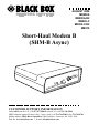
AUGUST 2000
ME800A
ME800A-R2
ME805-C
ME805-C-R2
ME810
Short-Haul Modem B
(SHM-B Async)
MAL
NOR BACK
LOOP
RD
TD
ASY
HOR
NC S
T
MO
HAUL
DEM
CUSTOMER SUPPORT INFORMATION
Order toll-free in the U.S.: Call 877-877-BBOX (outside U.S. call 724-746-5500)
FREE technical support 24 hours a day, 7 days a week: Call 724-746-5500 or fax 724-746-0746
Mailing address: Black Box Corporation, 1000 Park Drive, Lawrence, PA 15055-1018
Web site: www.blackbox.com • E-mail: [email protected]
SHM-B ASYNC
FEDERAL COMMUNICATIONS COMMISSION
AND
INDUSTRY CANADA
RADIO FREQUENCY INTERFERENCE STATEMENTS
This equipment generates, uses, and can radiate radio frequency energy and if
not installed and used properly, that is, in strict accordance with the
manufacturer’s instructions, may cause interference to radio communication. It
has been tested and found to comply with the limits for a Class A computing
device in accordance with the specifications in Subpart J of Part 15 of FCC rules,
which are designed to provide reasonable protection against such interference
when the equipment is operated in a commercial environment. Operation of
this equipment in a residential area is likely to cause interference, in which case
the user at his own expense will be required to take whatever measures may be
necessary to correct the interference.
Changes or modifications not expressly approved by the party responsible for
compliance could void the user’s authority to operate the equipment.
This digital apparatus does not exceed the Class A limits for radio noise emission from
digital apparatus set out in the Radio Interference Regulation of Industry Canada.
Le présent appareil numérique n’émet pas de bruits radioélectriques dépassant les limites
applicables aux appareils numériques de classe A prescrites dans le Règlement sur le
brouillage radioélectrique publié par Industrie Canada.
1
SHM-B ASYNC
NORMAS OFICIALES MEXICANAS (NOM)
ELECTRICAL SAFETY STATEMENT
INSTRUCCIONES DE SEGURIDAD
1. Todas las instrucciones de seguridad y operación deberán ser leídas antes
de que el aparato eléctrico sea operado.
2. Las instrucciones de seguridad y operación deberán ser guardadas para
referencia futura.
3. Todas las advertencias en el aparato eléctrico y en sus instrucciones de
operación deben ser respetadas.
4. Todas las instrucciones de operación y uso deben ser seguidas.
5. El aparato eléctrico no deberá ser usado cerca del agua—por ejemplo,
cerca de la tina de baño, lavabo, sótano mojado o cerca de una alberca,
etc..
6. El aparato eléctrico debe ser usado únicamente con carritos o pedestales
que sean recomendados por el fabricante.
7. El aparato eléctrico debe ser montado a la pared o al techo sólo como sea
recomendado por el fabricante.
8. Servicio—El usuario no debe intentar dar servicio al equipo eléctrico más
allá a lo descrito en las instrucciones de operación. Todo otro servicio
deberá ser referido a personal de servicio calificado.
9. El aparato eléctrico debe ser situado de tal manera que su posición no
interfiera su uso. La colocación del aparato eléctrico sobre una cama,
sofá, alfombra o superficie similar puede bloquea la ventilación, no se
debe colocar en libreros o gabinetes que impidan el flujo de aire por los
orificios de ventilación.
2
SHM-B ASYNC
10. El equipo eléctrico deber ser situado fuera del alcance de fuentes de calor
como radiadores, registros de calor, estufas u otros aparatos (incluyendo
amplificadores) que producen calor.
11. El aparato eléctrico deberá ser connectado a una fuente de poder sólo del
tipo descrito en el instructivo de operación, o como se indique en el
aparato.
12. Precaución debe ser tomada de tal manera que la tierra fisica y la
polarización del equipo no sea eliminada.
13. Los cables de la fuente de poder deben ser guiados de tal manera que no
sean pisados ni pellizcados por objetos colocados sobre o contra ellos,
poniendo particular atención a los contactos y receptáculos donde salen
del aparato.
14. El equipo eléctrico debe ser limpiado únicamente de acuerdo a las
recomendaciones del fabricante.
15. En caso de existir, una antena externa deberá ser localizada lejos de las
lineas de energia.
16. El cable de corriente deberá ser desconectado del cuando el equipo no
sea usado por un largo periodo de tiempo.
17. Cuidado debe ser tomado de tal manera que objectos liquidos no sean
derramados sobre la cubierta u orificios de ventilación.
18. Servicio por personal calificado deberá ser provisto cuando:
A:
El cable de poder o el contacto ha sido dañado; u
B:
Objectos han caído o líquido ha sido derramado dentro del
aparato; o
C:
El aparato ha sido expuesto a la lluvia; o
D:
El aparato parece no operar normalmente o muestra un cambio en
su desempeño; o
E:
El aparato ha sido tirado o su cubierta ha sido dañada.
3
SHM-B ASYNC
TRADEMARKS USED IN THIS MANUAL
Any trademarks mentioned in this manual are
acknowledged to be the property of the trademark
owners.
4
SHM-B ASYNC
1. Specifications
Transmission —
Data Rate (bps)
19,200
9600
4800
2400
Distance (miles/km)
1/1.6
2/3.2
3/4.8
4/6.4
NOTE:The above specifications are valid for 24- or 26-AWG unshielded
twisted-pair telephone cable insulated by polyethylene with a
mutual capacitance of 0.083 µf/mile. Shielded twisted-pair cable
will reduce the distance to one-third of the table value, due to the
additional capacitance contributed by the cable’s shielding. Actual
distances may vary depending on your specific operating
equipment and the cable you use.
Protocol — Asynchronous
Operation — 4-wire, full duplex, point-to-point
Line Interface — Balanced current loop; Receive lines
are protected through optical isolators rated at 1500
volts
Equipment Interface — EIA-232/CCITT V.24 interface
with a hardware handshake (selected through use of an
internal strap). Carrier Detect (CD) true (high)
indicates operating short-haul modem at the remote
5
SHM-B ASYNC
end of the loop. Interface is switch-selectable for
DTE/DCE configuration (pins 2 and 3 are reversed)
Connectors — (1) DB25 female, (1) 5-screw terminal
block
Diagnostics — Loopbacks provided by a front-panel
switch: Analog loopback on a 4-wire loop and digital
loopback on equipment interface (EIA-232)
Status Indication — Two bi-color LEDs indicate the
status of the transmitter and receiver. A green light
indicates a “low” logic level (-3 to -25V) on the EIA-232
interface; a red light indicates a “high” logic level (+3 to
+25V).
Operating Temperature — 32 to 112°F (0 to 50°C)
Humidity — 95%maximum, noncondensing
Enclosure — Standalone: High-impact plastic;
Rackmount: Aluminum alloy
Power — Power is supplied by a wall-mounted power
transformer. No more than 16 Vrms is present in unit.
6
SHM-B ASYNC
Primary: 115 VAC ±10%, 60 Hz, 5 watts (12 watts max.);
Primary: 230 VAC ±10%, 50/60 Hz; Secondary: 17 VAC,
700 mA
Size — Standalone: 1.4"H x 4.25"W x 4.5"D (3.8 x 10.9 x
11.7 cm); Rackmount: 5.25"H x 17"W x 9"D (13 x 43 x
23 cm)
Weight — Standalone: 1.3 lb. (0.6 kg), including
transformer; Rackmount: 3.7 lb. (1.7 kg), including
transformer
7
SHM-B ASYNC
2. Introduction
The Short-Haul Modem Model B Async (SHM-B Async)
is an asynchronous full-duplex 4-wire line
driver/receiver which allows two EIA-232 devices to
communicate at distances of up to 4 miles and at data
speeds of up to 19,200 bps. In addition to the
transmitter and receiver circuits, the SHM-B Async
includes EIA-232 control line interfaces, status monitor
LEDs, and a loopback switch. The SHM-B is available in
both a standalone version (ME800A) and a rackmount
version (ME805-C). Models ME800A-R2 and ME805-CR2 include cables.
The SHM-B is designed to operate over a 4-wire metallic
circuit. Optimum performance is obtained with twistedpair cable (see specifications). Most types of twisted-pair
cable may be used, often with little or no performance
degradation.
The SHM-B Async is designed for maximum operator
safety. There are no voltages greater than 12 VDC or 16
VAC present on the circuit board of the unit. The
Receive lines are protected from potential ground
differences through optical isolators rated at 1500 volts.
8
SHM-B ASYNC
3. Installation
Installation involves three basic steps: four-wire
connections; EIA-232 connection; switch settings.
3.1 Four-Wire Connections
Figure 1 shows the location of the terminal block on the
circuit board. Refer to Figure 2 to make the proper
connections between two SHM-B units.
NOTE: Transmit + (TX+) on one modem is wired
to Receive + (RX+) on the other modem; Transmit (TX-) is wired to Receive - (RX-). A ground
connection is optional.
1. If the unit is assembled, separate the top and
bottom panels at the front of the unit.
2. Push the rear connector to force out the front
panel and printed circuit board.
3. Route the four-wire cable through the open hole in
the rear panel of the enclosure.
4. Strip each of the four wires about 1⁄8".
9
SHM-B ASYNC
5. Insert the wires into the terminal strip; tighten the
screw terminals.
6. After you have made all four connections, wrap the
nylon cable tie (packaged with the SHM-B) around
the wires. Pull the tie tight around the wires to
secure them to the printed circuit board. Trim the
excess nylon tie with wire cutters or scissors.
J1 RS-232
CONNECTOR
EN
JUMPER
DIS
RTS/DTR
DCE
CONTROL
DTE/DCE
RX+
RXTX+
TXGROUND
DTE
S2 (LOOPBACK)
Figure 1. SHM-B board; 5-screw terminal block.
10
SHM-B ASYNC
TX+
RX+
TX-
RX-
RX+
TX+
RX-
TX-
SHM #1
SHM #2
Figure 2. Wiring diagram for two SHM-B units.
3.2 EIA-232 Connection
Connect the SHM-B to your computer or terminal with a
standard EIA-232 cable and DB25 connectors. Refer to
your equipment’s installation manual if you need
information on the exact EIA-232 signals required for
your equipment. Often, it is best to use only the
Transmit Data (TD), Receive Data (RD), and ground
lines if your equipment does not require the use of the
control signals Request To Send (RTS), Clear To Send
(CTS), Data Set Ready (DSR), etc. The SHM-B
generates levels for the control signals if you need to use
them. The table shows the pin connections at the
SHM-B.
11
SHM-B ASYNC
Table 1. EIA-232 Pin Connections on SHM-B
Pin Number
1
2
3
4
5
6
7
8
20
Signal Name
Protective Ground
Transmit Data/Receive Data (TD/RD)*
Receive Data/Transmit Data (RD/TD)*
Request to Send (RTS)
Clear to Send (CTS)
Data Set Ready (DSR)
Signal Ground
Carrier Detect (CD)
Data Terminal Ready (DTR)
*TD and RD can be reversed using the DTE/DCE switch, S1 on the circuit board. See
Section 3.3 for details.
3.3 Switch Settings
Refer to Figure 1 in this chapter. Switch S1 is used to
reverse the TD and RD lines on the EIA-232 interface.
This eliminates the need to swap these two lines in your
EIA-232 cables. If you connect the SHM-B to your
equipment using a “straight-through” or “2:2” cable,
then S1 must be set to the opposite of your device’s
configuration. For example, if your device is configured
as DTE, select DCE on S1. If you use a “2:3” or “3:2”
cable to connect the SHM-B to your equipment, then
the setting for S1 will be identical to your equipment’s
setting. Refer to your equipment’s manual for
12
SHM-B ASYNC
information concerning its DTE/DCE setting. Table 2
gives the EIA-232 pinning of the SHM-B with the
DTE/DCE switch in the DCE position.
Table 2. Pinning with DTE/DCE switch in the DCE position.
PIN NUMBER
1
2
3
4
5
6
7
8
20
SIGNAL NAME
Protective Ground
Transmitted Data TD*
Received Data RD*
Request to Send (RTS)
Clear to Send (CTS)
Data Set Ready (DSR)
Signal Ground
Received Line Signal Detector
Data Terminal Ready (DTR)
DIRECTION
—————
To DCE
From DCE
To DCE
From DCE
From DCE
—————
From DCE
To DCE
*Pins 2 and 3 (TD and RD) can be reversed using the DTE/DCE switch, S1 on the circuit
board. See Section 3.3 for details.
NOTE
Configure each SHM-B independently. Your local and
remote modems won’t necessarily be configured the same.
13
SHM-B ASYNC
3.4 Flow Control
The SHM-B uses a clever, yet simple way to allow this
unit to work with a broad line of equipment.
STANDARD EIA-232C HANDSHAKING (RTS/DTR CONTROL
JUMPER IN EN POSITION)
The individual SHM-B modems force their own DTR,
RTS, CTS, and DSR control lines HIGH (>+3V) when:
• The twisted-pair wires are installed correctly.
• Power is applied to both modems.
• No computer devices are attached to the modems.
This forces DCD HIGH on the remote modem; thus, the
remote modem knows to expect data. In this state, “all
systems are go.” The only way this state changes is if your
equipment overrides this condition. For example, if your
equipment drops DTR to a NEGATIVE signal, your
equipment’s DTR being low will override the SHM-B’s
DTR, and DCD on the remote modem will go LOW.
14
SHM-B ASYNC
Because DTR, DSR, RTS, and CTS are tied together
internally, dropping any one of these four signals to a
negative state will also drop DCD on the remote side to a
negative state. DCD will also go LOW if the remote
SHM-B is powered down, or if the twisted-pair wire is
broken.
X-ON/X-OFF MODE
(RTS/DTR CONTROL JUMPER IN DIS POSITION)
If X-ON/X-OFF characters are used for handshaking
control, rather than hardware logic levels, move the
RTS/DTR control jumper to the DIS position.
Typically, units that use software X-ON/X-OFF flow
control do not want RTS to affect DCD on the remote
SHM-B. Moving the jumper to the DIS position disables
the RTS/DCD relationship. The only thing that will
force DCD low with the jumper in the DIS position is the
absence of power on the remote SHM-B or a broken
twisted-pair wire.
15
SHM-B ASYNC
4. Operation
After completing the wiring and configuration
procedure, slide the printed circuit card back into the
case while pulling the data and power cables through
the holes in the back panel. The front panel will snap
into the front of the case when the printed circuit board
has been completely pushed to the back of the case.
Connect the SHM-B to your equipment, then plug the
wall transformer into its power source. Check the SHMB operation at both ends of the loop by pressing the
LOOPBACK switch, S2.
TD
TX+
RX+
TX-
RX-
(RS-232)
RD
RD
(RS-232)
RX+
TX+
RX-
TX-
SHM #1 in NORMAL mode.
TX+
TD
TX-
TD
SHM #2 in NORMAL mode.
RX+
RX-
(RS-232)
RD
(RS-232)
RX+
RD
TX+
TX-
TD
RX-
SHM #1 in LOOPBACK mode.
SHM #2 in NORMAL mode.
Figure 3. Activating the LOOPBACK switch.
16
SHM-B ASYNC
When in loopback mode, the switch button indicator
will appear to the sender. If a CRT terminal is connected
to the SHM-B, typing characters on the keyboard should
result in the same characters appearing on the CRT
screen. If no characters appear, check your EIA-232
connections and the setting of S1. See Figure 3 for an
illustration of the loopback mode.
The TD and RD LEDs on the front panel of your SHM-B
indicate the status of the SHM-B transmitter and
receiver, respectively. Green indicates a LOW EIA-232
level and red indicates a HIGH EIA-232 level. The LEDs
will modulate as data is transmitted and received by the
SHM-B. Remember that these LEDs are monitoring the
actual received and transmitted signals, not the TD and
RD lines of the EIA-232 interface.
When the loopback test is completed, press the
LOOPBACK switch again to return the SHM-B to
normal mode. The switch button indicator should now
be black. Data transmission between the two modems
will now be possible.
If you experience problems communicating between the
two SHM-Bs, use Table 1 to help diagnose the problem.
17
SHM-B ASYNC
5. Rackmount Installation
The SHM-B Async Card is a rack mount unit (ME805-C)
that installs in a standard 19-inch panel rack. (You can
use the SHM-B Rack [ME810], which can hold up to 16
cards.) The SHM-B Async Card will occupy 5.25 inches
of vertical rack space, and is 9 inches deep.
To install the SHM-B Rack, first remove the acrylic front
panel by pulling out the six plunger latches on the front
of the panel, then pulling on opposite-side plungers to
loosen and remove the panel.
Locate the four 10/32 Phillips-head screws that were
shipped with the SHM-B Rack. Use these screws to fasten
the SHM-B Rack to your rack.
CAUTION
Do not attempt to use screws which are not countersunk, as
this will result in damage to the plastic front panel when it is
installed.
Wire each SHM-B board according to Figures 1 and 2 in
this manual. It is easiest to first feed all of the wires and
cables through the rack. Then you can make the
necessary circuit board connections with the circuit
boards positioned in front of the rack; this allows for the
18
SHM-B ASYNC
easiest access to the terminals, switches, etc.
After a SHM-B Card is wired, it can then be inserted into
an open slot in the SHM-B rack. Be certain that the circuit
board has mated with the power pins on the SHM-B rack before
applying force to fully seat the board; otherwise you may
damage the board and power pins.
When all boards have been wired and plugged into the
rack, plug the wall transformer into its power source.
You should be able to communicate as described in
Chapter 4. When all channels are operating, attach the
SHM-B Rack front panel by first aligning the plunger
latches with their respective holes in the rack. Press on
the top and bottom of the panel to properly seat it, then
firmly press in all six of the plunger latches to retrain the
panel.
19
SHM-B ASYNC
6. Troubleshooting Guide
The following information will help you troubleshoot
your installation if problems develop. If your particular
situation isn’t listed here, call Technical Support for
assistance. Have ready a description of the problem with
your installation, your DTE equipment make and
models, your equipment’s DTE/DCE configuration and
flow control type (hardware or software), your EIA-232
cable pinouts, and what (if anything) you have already
done to correct the situation.
SYMPTOM: LEDs do not light when power transformer
is plugged into a wall outlet.
1. Is the power connection loose? Try moving or
nudging the wall transformer.
2. Are there broken power leads? Disconnect the power
supply. Remove the printed circuit board from the
chassis. Inspect the three leads from the transformer
for continuity.
3. The SHM-B is defective.
4. SHM-B Async Card: Make certain that the SHM-B’s
20
SHM-B ASYNC
printed circuit board is properly inserted and fully
seated against the motherboard of the rack.
SYMPTOM: No data transfer in one or both directions
(to, from, or to-and-from the SHM-B).
1. Monitor the TD LED on the sending-end modem
while sending data. The light should flash red/green.
If not, check the DCE/DTE switch on that unit. Once
you get a TD LED flashing on that unit,
simultaneously the RD LED should flash on the other
SHM-B unit. If not, go to step 2.
2. Inspect the wiring between the two modems. Have the
wires been properly installed? Transmit + (TX+) on
one modem must be wired to Receive + (RX+) on the
other modem; also, Transmit - (TX-) must be wired to
Receive - (RX-). Refer to Figure 2 during your
inspection of the four-wire circuit.
3. Try a local test using the Loopback mode (see
Chapter 4). If there is no transfer, check the setting of
S1 and the wiring of your EIA-232 cable.
4. The EIA-232 control signals are at the wrong levels.
Check the EIA-232 interface using a breakout box.
21
SHM-B ASYNC
Pins 4, 5, 6, 8, and 20 should all be HIGH to enable
communication.
5. If pin 8 (Carrier Detect) is low, this indicates:
• a defective transmission line or connection
• a defective remote SHM-B
• remote SHM-B without power
SYMPTOM: TD and RD LEDs indicate data activity, but
data communication doesn’t exist.
1. Check the wiring of the EIA-232 port. Refer to Section
3.2 for information.
2. Check the setting of S1. Refer to Section 3.3 for
information.
SYMPTOM: Transmitted and/or received data is full of
errors (garbled data).
1. Check for reversal of polarity on the four-wire
connection. Refer to Section 3.1 and Figure 2.
2. Check word structure and speed settings on your
22
SHM-B ASYNC
computing equipment for consistency.
3. Wire the SHM-B units back-to-back, eliminating the
twisted-pair; see if you still have errors.
• If you do have errors, then test each SHM
individually in the following way: loopback one
SHM’s Transmit-to-Receive by using two short
pieces of wire. Connect that SHM to a dumb
terminal and key in characters; look for a good
loopback. A good loopback verifies a SHM-B in
proper working condition.
• If you don’t have errors, you have verified a
problem with the twisted-pair cable.
SYMPTOM: Occasional data errors.
1. The transmission distance/bps data rate capability
rate may have been exceeded. Refer to Chapter 1 for
information about valid data transmission distances
and bps rates.
2. There is a poor quality loop (four-wire circuit). Try
using a different four-wire circuit, or rewire the
existing circuit.
23
SHM-B ASYNC
3. Check the path of your four-wire circuit for potential
sources of interference (fluorescent lighting,
electrical motors, etc.). Such sources of electrical
“noise” can provide an environment in which
unwanted signals are induced onto your four-wire
circuit. Also, check to see if an adjacent four-wire
cable carrying a separate data stream is creating
“crosstalk.” It may be that the data signal is jumping
from the adjacent cable onto the four-wire circuit
between the two SHM-B modems (another type of
induced signal).
• While you are checking your cable for sources of
noise and crosstalk, check the cable for
irregularities in the shield. Also, reconsider the
cable’s ratings for attenuation, capacitance, and
impedance. You may need to install a higherquality cable for your particular installation.
• Your AC power source may be the culprit. Check
your AC power at the wall socket and confirm that
it is within the range given in Chapter 1.
24
SHM-B ASYNC
SYMPTOM: TD or RD indicator is steadily on red with
no data attempting to pass (no DTEs attached).
Check for reversal of polarity on the four-wire
connection.
25
© Copyright 2000. Black Box Corporation. All rights reserved.
1000 Park Drive • Lawrence, PA 15055-1018 • 724-746-5500 • Fax 724-746-0746