1
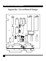
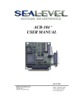
MARCH 2000
IC110C
IC174C
Dual Port RS-232 Serial Interface
CUSTOMER
SUPPORT
INFORMATION
Order toll-free in the U.S. 24 hours, 7 A.M. Monday to midnight Friday: 877-877-BBOX
FREE technical support, 24 hours a day, 7 days a week: Call 724-746-5500 or fax 724-746-0746
Mail order: Black Box Corporation, 1000 Park Drive, Lawrence, PA 15055-1018
Web site: www.blackbox.com • E-mail: [email protected]
DUAL PORT RS-232 SERIAL INTERFACE
FEDERAL COMMUNICATIONS COMMISSION
AND
CANADIAN DEPARTMENT OF COMMUNICATIONS
RADIO FREQUENCY INTERFERENCE STATEMENTS
This equipment generates, uses, and can radiate radio frequency energy and
if not installed and used properly, that is, in strict accordance with the
manufacturer’s instructions, may cause interference to radio communication.
It has been tested and found to comply with the limits for a Class A
computing device in accordance with the specifications in Subpart J of Part 15
of FCC rules, which are designed to provide reasonable protection against
such interference when the equipment is operated in a commercial
environment. Operation of this equipment in a residential area is likely to
cause interference, in which case the user at his own expense will be required
to take whatever measures may be necessary to correct the interference.
Changes or modifications not expressly approved by the party responsible for
compliance could void the user’s authority to operate the equipment.
This digital apparatus does not exceed the Class A limits for radio noise emission from
digital apparatus set out in the Radio Interference Regulation of the Canadian
Department of Communications.
Le présent appareil numérique n’émet pas de bruits radioélectriques dépassant les limites
applicables aux appareils numériques de la classe A prescrites dans le Règlement sur le
brouillage radioélectrique publié par le ministère des Communications du Canada.
TRADEMARKS USED IN THIS MANUAL
AT and IBM are registered trademarks of International Business Machines
Corporation. PC/XT and XT are trademarks of International Business
Machines Corporation.
DUAL PORT RS-232 SERIAL INTERFACE
Contents
Chapter
Page
1. Specifications...................................................................................................1
2. Introduction ....................................................................................................2
2.1 Overview..................................................................................................2
2.2 What’s Included......................................................................................2
2.3 Features ...................................................................................................3
2.4 Technical Description ............................................................................4
3. Address Selection ............................................................................................6
4. Option Selection .............................................................................................8
5. Installation.....................................................................................................10
5.1 Installing the Adapter in Your Operating System ...............................10
5.1.1 Windows 3.1x...............................................................................10
5.1.2 Windows 95/98 ...........................................................................10
5.1.3 Windows NT ................................................................................10
5.2 Installing the Hardware ........................................................................10
Appendix: Cicuit-Board Design ........................................................................11
CHAPTER 1: Specifications
1. Specifications
Protocol — Asynchronous
Number of Ports — 2
Speed — IC110C: Up to 115.2 Kbps; IC174C: 460.8 kbps and higher
Operation — RS-232
Connectors — (2) DB9M
Maximum Distance — 50 ft. (15.2 m) @ 19.2 Kbps with 2500 pF max. cable
capacitance (lower capacitance will allow greater distances)
Communications Chip — IC110C: 16550 UART; IC174C: 16950 UART
MTBF — >150,000 hours
MTTR — <0.25 hours
Materials — Boards are solder mask over bare copper or tin nickel
Operating Temperature — 32° to 122°F (0° to 50°C)
Storage Temperature — -4° to 158°F (-20° to 70°C)
Humidity — 0 to 90% relative humidity, noncondensing
Power — +5 VDC @ 270 mA ±12 V @ 50 mA
Size — 5"W x 5"D (12.7 x 12.7 cm)
Weight — 0.2 lb. (0.1 kg)
1
DUAL PORT RS-232 SERIAL INTERFACE
2. Introduction
2.1 Overview
The Dual Port RS-232 Serial Interface provides your PC system with two RS232 asynchronous ports. Connect to any device that uses the RS-232 protocol,
such as modems, data-entry terminals, and plotters.
The Serial Interface also includes a serial utility diskette with Seacom, a DOS
interrupt and driver package. Seacom allows data to be buffered, eliminating
data loss in high-speed data transfers. It also allows more than 4 ports (256
max.) to be configured and utilized under DOS.
The README file on the serial utility diskette contains information about the
latest changes and revisions. To view this file, insert the diskette into drive A
or B and type A:TYPE READ.ME|MORE [ENTER] or B:TYPE
READ.ME|MORE [ENTER].
2.2 What’s Included
Your Serial Interface should come with the following items. If any of these
items are missing or damaged, contact your supplier.
(1) Dual Port RS-232 Serial Interface,
(2) serial utility software diskettes: (1) for 32-bit Windows®,
(1) for DOS and Windows®3.1x
This manual
2
CHAPTER 2: Introduction
2.3 Features
Listed below are the special features your Serial Interface offers.
• Each port is independently addressable.
• Eight interrupt options, including AT interrupts, for simple integration
into existing systems.
• IRQs can be shared or individually set for each port.
• Supports Interrupt Sharing—only one interrupt line required for multiple
ports.
• Supports any character set defined by binary notation.
• 16550 UARTs (IC110C) or 16950 UARTs (IC174C) help ensure against
data loss.
• Faster baud rates—up to 115.2 Kbps (IC110C) or 460.8 kbps and higher
(IC174C).
• Dual DB9 male AT® style connectors.
• Individually selectable address and interrupt (2–5 and 10, 11, 12, or 15 on
the AT connector) for each port.
3
DUAL PORT RS-232 SERIAL INTERFACE
2.4 Technical Description
The Dual Port RS-232 Serial Interface provides the PC/XT™/AT/80X86
computer with two additional serial ports for terminals, modems, printers,
etc. The Dual Port RS-232 Serial Interface can be configured as COM1:
through COM4:, or any other I/O address.
The Dual Port RS-232 Serial Interface (IC110C) utilizes the same 16550
UART chip found in the IBM® asynchronous adapter. This chip features
programmable baud rate, data format, and interrupt control. Refer to the
IBM Technical Reference for details on programming the chip. The IC174C uses
the 16950 UART chip.
Each serial port can be set as COM1:, COM2:, or any other I/O address set up
to 3FF hex, providing total compatibility with most communications software
and languages. Some software packages require the use of the modem
handshake signals such as CTS or DCD. Consult your software manual to
determine handshake-signal requirements. If no requirements are
mentioned, or if you are not sure, a safe configuration is to connect (in your
cable hood) DTR to DSR and DCD, and tie RTS to CTS. This usually satisfies
the modem signal requirements for most communications software.
The table on page 5 shows the connector pinouts for ports J1 and J2 (DB9).
Note that this is the same RS-232 pinout as the DB9 serial AT connector.
4
CHAPTER 2: Introduction
Pin Number
Signal Name
Mode
3
7
4
5
2
1
6
8
9
Transmit Data (TD)
Request To Send (RTS)
Data Term Ready (DTR)
Ground (GND)
Receive Data (RD)
Data Carrier Detect (DCD)
Data Set Ready (DSR)
Clear To Send (CTS)
Ring Indicator (RI)
Output RS-232
Output RS-232
Output RS-232
––––––––––––
Input RS-232
Input RS-232
Input RS-232
Input RS-232
Input RS-232
5
DUAL PORT RS-232 SERIAL INTERFACE
3. Address Selection
NOTE
Be sure to set the address selections and jumper options before
installation.
Each serial port on the Dual Port RS-232 Serial Interface occupies 8
consecutive I/O locations. A DIP switch is used to set the base address for
these locations. Be careful when selecting the base address as some selections
conflict with existing PC ports. The following table shows several examples
that usually do not cause a conflict. SW1 sets the I/O address for Port 2 (the
upper connector), while SW2 sets the address for Port 1 (the lower
connector).
Address
Hex
280-287
2A0-2A7
2E8-2EF
2F8-2FF
3E8-3EF
300-307
328-32F
3F8-3FF
Binary
A9
A0
1010000XXX
1010100XXX
1011101XXX
1011111XXX
1111101XXX
1100000XXX
1100101XXX
1111111XXX
Switch Position Setting
1
OFF
OFF
OFF
OFF
OFF
OFF
OFF
OFF
2
ON
ON
ON
ON
OFF
OFF
OFF
OFF
3
OFF
OFF
OFF
OFF
OFF
ON
ON
OFF
4
ON
ON
OFF
OFF
OFF
ON
ON
OFF
5
ON
OFF
OFF
OFF
OFF
ON
OFF
OFF
6
ON
ON
ON
OFF
ON
ON
ON
OFF
7
ON
ON
OFF
OFF
OFF
ON
OFF
OFF
Typically COM1:=3F8h; COM2:=2F8h; COM3:=3E8h; COM4:=2E8h
If you do not see an address in the table that is compatible with your software,
6
CHAPTER 3: Address Selection
you can determine the switch setting for a particular address by using the
following illustration. The illustration shows the correlation between the DIP
switch setting and the address bits used to determine the base address. In the
figure below, the address 300 hex through 307 hex is selected (300 HEX =11
0000 0XXX in binary representation). Note that setting the switch ON (or
closed) corresponds to a “0” in the address, while leaving it OFF (or open)
corresponds to a “1.”
A9
A3 EN
ON
1
2
3
4
5
6
7
8
7
DUAL PORT RS-232 SERIAL INTERFACE
4. Option Selection
NOTE
Be sure to set the address selections and jumper options before
installation.
The board contains several jumper straps for each port which must be set for
proper operation.
Port Enable/Disable
Each port on the Dual Port RS-232 can be enabled or disabled with switch
position 8 on the DIP switch. The port is enabled with the switch ON (or
closed) and disabled when OFF (or open). Switch 2 (SW2), position 8
enables/disables Port 1, while Switch 1 (SW1), position 8 enables/disables
port 2. If either port is disabled, be sure to also disable the interrupt request
for that port by removing the IRQ jumper (see Figure 4-1).
Setting the Interrupt Request
Headers E1 and E2 select the interrupt request for each serial port. If COM1:
is selected, this jumper must be on the IRQ4 setting. If COM2: is selected, this
jumper must be on IRQ3. Both ports can be set to the same IRQ setting. If no
interrupt is desired, remove the jumper.
NOTE
Most communications software applications default COM3: to IRQ4 and
COM4: to IRQ3. This requires the sharing of interrupts between COM1:
and COM3:, and between COM2: and COM4:. While this is the default, it
is not always the best setting. Check your software configuration
instructions to determine the most appropriate IRQ setting.
8
10
11
12
15
2
3
4
5
CHAPTER 4: Option Selection
Figure 4-1. Header E1 and E2 (IRQ 4 selected).
E4
M
N
E3
Headers E3 and E4 select the (normal) single-interrupt-per-board mode or
the multi-interrupt mode, which allows you to share both interrupts on this
card. The multi-interrupt mode also allows you to share the IRQ signal(s) with
other cards that support multiple interrupts.
Figure 4-2. Headers E3 and E4 in Normal Mode.
9
DUAL PORT RS-232 SERIAL INTERFACE
5. Installation
IMPORTANT
You MUST set up the operating system BEFORE you physically install
the Card.
5.1 Installing the Adapter in Your Operating System
If you are installing an ISA adapter in DOS, OS/2®, or QNX, please refer to the
appropriate directory on one of the Serial Utilities Disks for instructions.
5.1.1 WINDOWS 3.1X
Please refer to the /WINDOWS sub-directory on the Serial Utilities Diskette for
help files and current information on the installation of the Card in this operating
environment.
5.1.2 WINDOWS 95/98
For the ISA card, run setup the Serial Utilities Diskette before installing the
card. Make note of the resources that Windows assigns the adapter and set the
adapter to match those resources. Power down the computer and install the
adapter.
5.1.3 WINDOWS NT
For the ISA card, run setup on disk two of the Serial Utilities Diskettes before
installing the card. After installing the software, refer to the help file that
automatically comes up for installation instructions.
5.2 Installing the Hardware
The Dual Port RS-232 can be installed in any of the PC expansion slots,
except J8 on the original IBM XT™ and Portable. Follow these steps to install
the card:
1. Remove the PC case.
2. Remove the blank metal slot cover.
3. Gently insert the board.
10
CHAPTER 5: Installation
4. Replace the screw.
5. Replace the cover.
If you wish to change any resources assigned to the adapter, refer to the help
file installed in the Black Box folder in the Start, Programs menu.
Installation is complete.
11
DUAL PORT RS-232 SERIAL INTERFACE
Appendix: Circuit-Board Design
P2
C2
C1
C3
U2
SW1
U3
E1
E2
PORT1 PORT2
2
2
3
3
4
4
5
5
10
10
11
11
12
12
R1
15
15
U1
U4
C4
SW2
R2
P1
Y1
U5
U6
C6
C5
R3
M
C7
N
1
1
U10
U9
E3
E4
U7
C8
1
14
12
J1
1
6
D1
R4
D2
R5
U6
C9
J2
1
6
5
9 J4
13
25
5
9
1
6
5
9
J3
P2
P2
P2
P2
P1
P1
P1
P1
P1
P1
P1
P1
P1
P1
P1
P1
P1
P1
P1
P1
P1
P1
D6
D5
D4
D3
B23
B24
B25
B4
A2
A3
A4
A5
A6
A7
A8
A9
B14
B13
A29
A30
A31
B2
A11
A28
A27
A26
A25
A24
6
7
5
3
1
SW1
SW1
SW1
SW1
SW1
11
10
12
14
16
IRQ15
IRQ12
IRQ11
IRQ10
IRQ5
IRQ4
IRQ3
IRQ2
D7
D6
D5
D4
D3
D2
D1
D0
RD/
WR/
A2
A1
A0
RESET
GND
4
SW1
13
PORT 1
2
SW1
15
AEN
A3
A4
A5
A6
A7
A8
A9
A8
A6
A4
AEN
A3
A5
A7
A9
BRD/
GND
GND
GND
3
4
5
6
7
8
9
2
1
19
11
13
15
17
19
2
4
6
8
1
3
5
7
9
12
14
16
18
2
4
6
8
11
13
15
17
VSS
P>Q
P=Q
VDO
U5
Y1
Y2
Y3
Y4
Y1
Y2
Y3
Y4
10
18
16
14
12
20
9
7
5
3
B2
B3
B4
B5
B6
B7
B8
2
4
6
8
10
12
14
16
2
4
6
8
10
12
14
16
E1
E2
74LS245
A2
A3
A4
A5
A6
A7
A8
1
3
5
7
9
11
13
15
1
3
5
7
9
11
13
15
1
17
16
15
14
13
12
11
8
1
R1
2
2
16
14
12
10
11
13
15
9
2
E3
E4
1
3
DB1
DB2
DB3
DB4
DB5
DB6
DB7
DB0
1
3
2
4
6
7
5
3
1
SW2
SW2
SW2
SW2
SW2
SW2
SW2
GND
GND
1
1
PORT 2
BWR/
BRD/
BRESET
BA0
BA1
BA2
GND
SW1
+5V
GND
GND
+5V
GND
+5V
10
19
20
20
G
VDO
10
DIR VSS
18
A1
B1
U6
74LS244
A1
A2
A3
A4
VDO/VSS
G
A1
A2
A3
A4
VDO/VSS
G
74LS244
U5
74LS682
Q0
Q1
Q2
Q3
Q4
Q5
Q6
Q7
P0
P1
P2
P3
P4
P5
P6
P7
U1
1
A23
D1
2
2
A8
A6
A4
AEN
A3
A5
A7
A9
+5V
D2
R3
2
1
5
6
74LS125A
11
U7
12
13
9
8
74LS125A
10
U7
74LS125A
4
U7
+5V
10
1
GND
GND
19 8 SW2
20
GND
VSS
P>Q
P=Q
VDO
74LS682
Q0
Q1
Q2
Q3
Q4
Q5
Q6
Q7
P0
P1
P2
P3
P4
P5
P6
P7
74LS125A
3
U7
3
5
7
9
GND 12
14
16
18
2
4
6
8
11
13
15
17
U4
P1
P1
P1
P1
P1
P1
9
B31
B1
B29
B3
B7
B9
+5V
1
R2
+5V
GND
GND
GND
GND
+
TD1
1
2
3
4
5
6
7
8
33
32
34
31
24
23
15
30
11
40
20
1
2
3
4
5
6
7
8
33
32
34
31
24
23
15
30
11
40
20
7
1
-12V
8250A
VDO XTAL1
VSS XTAL2
MR
D0
CS0
D1
CS1
D2
CS2
D3
DISTR
D4
DISTR
D5
DOSTR
D6
DOSTR
D7
ADS
DTR
RCLK
RTS
SIN
CTS
OUT1
DSR
OUT2
CSOUT DCD
RI
DDIS
BAUDOUTA0
A1
INTRPT
A2
SOUT
U3
8250A
XTAL1
XTAL2
MR
D0
CS0
D1
CS1
D2
CS2
D3
DISTR
D4
DISTR
D5
DOSTR
D6
DOSTR
D7
ADS
DTR
RCLK
RTS
SIN
CTS
OUT1
DSR
OUT2
CSOUT DCD
RI
DDIS
BAUDOUTA0
A1
INTRPT
A2
SOUT
VDO
VSS
U2
TXCO
OUT
VDO
Y1
VSS
NC
16
17
35
12
13
14
22
21
19
18
25
9
10
36
37
38
39
28
27
26
16
17
35
12
13
14
22
21
19
18
25
9
10
36
37
38
39
28
27
26
+12V
8
14
GND
DTR1
VSS VEE-
9
+5V
MC145406
2
2
3
2
3
2
3
2
3
2
3
2
3
2
3
2
3
8
7
DTR1/
DTR1/
6
11
10
DSR1/
RTS1/
RTS1/
CTS1/
CTS1/
TD1/
TD1/
RD1/
RD1/
RI1/
RI1/
DCD1/
DCD1/
RI2/
RI2/
DCD2/
DCD2/
DTR2/
DTR2/
DSR2/
DSR2/
RTS2/
RTS2/
CTS2/
CTS2/
TD2/
DSR1/
-12V
+12V
GND
+12V
-12V
+12V
TD2/
RD2/
RD2/
5
12
4
13
RTS1
3
14
BWR/
1
2
TD1
VDO VEE+
U10
MC1489
15
16
6
V+
ENA
OUTA INA
ENB
OUTB INB
8
ENC
OUTC INC
11
END
OUTD IND
GND
3
U9
14
2
1
5
4
9
10
12
13
7
8
9
MC145406
7
6
10
11
4
3
2
1
5
VSS VEE-
VDO VEE+
U8
12
13
14
15
16
BRD/
RD1
CTS1
DSR1
DCD1
RI1
BA0
BA1
BA2
GND
+5V
+5V
GND
BWR/
RD2
CTS2
DSR2
DCD2
RI2
BA0
BA1
BA2
DTR2
RTS2
TD2
+5V
BRD/
BRESET
BRESET
GND
+5V
+5V
1 C9 1 C6 1 C1 1 C2 1 C3 1 C4 1
1
1
C5
C7
DTR1
RTS1
+5V
GND
TD2
DTR2
RTS2
C8
+5V
+5V
-12V
+12
DB0
DB1
DB2
DB3
DB4
DB5
DB6
DB7
DB0
DB1
DB2
DB3
DB4
DB5
DB6
DB7
2
A22
R5
R4
2
1
2
1
2
P1
P1
P1
P1
P1
P1
P1
P1
4
4
6
6
7
7
8
8
3
3
2
2
9
9
1
1
22
9
8
1
20
4
6
6
4
7
5
8
2
3
3
2
J2
J3
J2
J3
J2
J3
J2
J3
J2
J3
J2
J3
J1
J4
J1
J4
J2
J3
J2
J3
J1
J4
J1
J4
J1
J4
J1
J4
J1
J4
J1
J4
APPENDIX: Circuit-Board Design
13
© Copyright 2000. Black Box Corporation. All rights reserved.
1000 Park Drive
•
Lawrence, PA 15055-1018
•
724-746-5500
•
Fax 724-746-0746