1
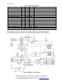
MED100A 304 pg. 1 / 4
6132-r1
Model MED100A
Fiber Optic Modem Sends
RS-232, 422, 485 Signals Up to 2.5 Miles
CE
Description
The MED100A is designed to provide the most versatile connection possible between any asynchronous serial equipment
using Fiber Optic cable. It allows any two pieces of asynchronous serial equipment to communicate full or half-duplex over
two fibers at typical distances up to 2.5 miles. The converter can also be set up in "Repeater" mode to create a multi-drop
master/slave configuration, allowing one serial device to talk to multiple slave devices around a fiber ring. The DIN rail
mountable box makes it ideal for industrial cabinets and enclosures.
RS-232 data signals up to 115.2K bps and RS-422, or RS-485 data signals up to 460K bps are supported. Different
standards can be mixed and matched to allow RS-232 devices to connect to your RS-422 or RS-485 system. This means
the MED100A can replace converters and isolators when connecting remote devices, while providing the EMI/RFI and
transient immunity of optical fiber.
The MED100A supports both the Transmit and Receive data lines, and provides full hardware control of the RS-422/485
driver with automatic Send Data Control circuit. Timeouts are dip-switch selectable between 0.10 and 2.2 ms. All serial
connections are provided on terminal blocks, while the multimode fiber is connected via two ST connectors. The unit is
powered by 10 to 30VDC at 140 mA max.
RS-232 Connections
Connection of the MED100A is simple and straightforward. The RS-232 driver and receiver are connected to 2 terminal
blocks. The RS-232 DATA OUT is on terminal block (A), and the RS-232 DATA IN is on terminal block (D). Ground is
located on terminal block (B) and (C), and power comes in on terminal block (F).
RS-422 and RS-485 Connections
The RS-422/485 driver and receiver are connected to 4 terminal blocks. Signal ground is on terminal block (M), and power
comes in on terminal block (J). When connecting to a four-wire RS-422/485 device or system, connect the output of your
device to terminal block (L) (RDB or RD+) and terminal block (K) (RDA or RD+). Connect the input to your device to
terminal block (H) (TDB or TD+) and terminal block (G) (TDA or TD-). For two-wire RS-485 systems, the driver and
receiver of the MED100A must be connected together by tying terminal blocks (L) and (H) together and (G) and (K)
together. This allows the MED100A to communicate half-duplex over the same pair. Refer to Figure 1 for connection
diagrams to your RS-422 or RS-485 equipment.
If termination is needed, the PCBD is laid out to allow a termination resistor (Rt) to be soldered in across the RD(A) and
RD(B) lines. The off-state bias resistor values can also be changed by removing R8 and R16 and replacing them with
through-hole components.
Figure 1: RS-422/485 Connection Diagrams
422/485 4W Device
MED100A
FOSTCDR
TD A (-)
(K) RD A
TD B (+)
(L) RD B
RD A (-)
(G) TD A
RD B (+)
(H) TD B
GND
(M)
485 2 Wire Device
Data A (-)
MED100A
FOSTCDR
(K) RD A
(L) RD B
(G) TD A
Data B (+)
GND
(H) TD B
(M)
Black Box Corporation - 1000 Park Drive - Lawrence, PA 15055-1018
Tech Support and Ordering: 724-746-5500 - Fax: 724-746-0746
To contact us about Black Box products or services: [email protected]
MED100A 304 pg. 2 / 4
6132-r1
Fiber Optic Connections
The MED100A uses a separate LED emitter and photo-detector operating at 820 nm wavelength. Connections to the
emitter and detector are on ST type connectors. Most multimode glass fiber size can be used including 50/125 µm,
62.5/125 µm, 100/140 µm, and 200 µm. One fiber is required for each connection between a transmitter and receiver. In a
point to point configuration, two fibers are required between the two modems, one for data in each direction. A multi-drop
ring configuration requires one fiber between TX and RX around the loop. See Figure 2 for typical point-to-point and multidrop configurations.
The most important consideration in planning the fiber optic link is the “power budget” of the fiber modem. This value
represents the amount of loss in dB that can be present in the link between the two modems before the units fail to
perform properly. This value includes line attenuation as well as connector loss. For the MED100A the typical connector to
connector power budget is 12.1 dB. Because 62.5/125 µm cable typically has a line attenuation of 3 dB per Km at 820 nm,
the 12.1 dB power budget translates into 2.5 miles. This assumes no extra connectors or splices in the link. Each extra
connection would typically add 0.5 dB of loss, reducing the possible distance by 166 m (547 ft.). The actual loss should be
measured before assuming distances.
Figure 2: Typical Setups
Point to Point
RS-232
RS-422
or RS-485
Device
or System
MED100A
FOSTCDR
SW1:6=OFF
SW1:6 = OFF
TX
RX
RX
Duplex
Multimode
Fiber
TX
MED100A
FOSTCDR
SW1:6=OFF
SW1:6
= OFF
RS-232
RS-422
or RS-485
Device
or System
Multi-Drop Ring
Full Duplex
RS-232
RS-422
or RS-485
Device
or System
TX
MED100A
FOSTCDR
SW1:6 = OFF
SW1:6=OFF
Multimode
Fiber
RX
MASTER
SW1:6 = ON
MED100A
FOSTCDR
SW1:6=ON
RS-232
RS-422
or RS-485
Device
or System
RX
TX
SLAVE
SW1:6 = ON
The Dip-Switch (SW1) on the MED100A defines the
mode of operation when being used for RS-422 or RS485. Positions 1 through 5 on the switch determine the
timeout of the RS-485 driver. Because the driver is
controlled by hardware, a specific time must be set to
tell the hardware how long to wait for data on the fiber
side before turning off the RS-422/485 driver. If this time
is set too short, the driver could be disabled before
transmission is complete, resulting in data corruption. If
the time is set too long, the RS-485 device may respond
before the RS-422/485 driver in the MED100A is
disabled, corrupting this response. We recommend that
the timeout be set for approximately one character time
or longer. The character times for several different baud
rates are selectable on switch positions 1 through 5. If
you need a different timeout than what is provided, R10
can be removed and replaced with a different value R9.
Table 1 shows different timeout values for the switch
positions as well as typical R9 replacement values.
MED100A
FOSTCDR
SW1:6=ON
SLAVE
MED100A
FOSTCDR
SW1:6=ON
SW1:6 = ON
SLAVE
Dip-Switch Setup
RX
TX
RX
TX
RS-232
RS-422
or RS-485
Device
or System
RS-232
RS-422
or RS-485
Device
or System
Table 1: RS-485 Timeout Selection
Baud Rate Pos. 1
Pos. 2
Pos. 3
Pos. 4
Pos. 5
R9
Time(ms)
1200
ON
OFF
OFF
OFF
OFF
820 KΩ
8.20
2400
ON
OFF
OFF
OFF
OFF
430 KΩ
4.30
4800
OFF
OFF
OFF
OFF
ON
Not Used
2.20
9600
OFF
OFF
OFF
ON
OFF
Not Used
1.30
19.2K
OFF
OFF
ON
OFF
OFF
Not Used
0.56
38.4K
OFF
ON
OFF
OFF
OFF
Not Used
0.27
57.6K
ON
OFF
OFF
OFF
OFF
Not Used
0.22
76.8K
ON
OFF
ON
ON
OFF
Not Used
0.14
115.2K
ON
ON
ON
OFF
OFF
Not Used
0.10
153.6K
ON
OFF
OFF
OFF
OFF
6.2 KΩ
0.06
230.4K
ON
OFF
OFF
OFF
OFF
4.3 KΩ
0.04
460.8K
ON
OFF
OFF
OFF
OFF
2.2 KΩ
0.02
Black Box Corporation - 1000 Park Drive - Lawrence, PA 15055-1018
Tech Support and Ordering: 724-746-5500 - Fax: 724-746-0746
To contact us about Black Box products or services: [email protected]
MED100A 304 pg. 3 / 4
6132-r1
Position 6 of SW1 sets the unit in a “Multidrop” mode or a “Point-to-Point” mode. When the MED100A is set in a
“Multidrop” mode, data arriving on the Fiber Optic receiver is repeated back out the transmitter. When set in a “Point-toPoint” mode, data arriving at the Fiber optic receiver is not sent back out the Fiber Optic transmitter. Position 6 must be
turned “On” when the MED100A is to be used in a multi-drop ring configuration. It must be turned “Off” when the
MED100A is to be used as either end of a point-to-point communication line. See Figure 3 for typical system setups using
the MED100A in its different modes.
Positions 7 and 8 of SW1 determine when the RS-422/485 driver and
receiver are enabled. Position 7 controls the driver and Position 8
controls the receiver. For RS-422 operation, set both switches to the
“Off” position. For multi-drop RS-485 four-wire systems, position 7
should be “On” and position 8 should be “Off.” This allows the receiver
to be enabled all of the time and eliminates some possible timing
problems. For RS-485 two-wire systems, both switches should be in the
“On” position. This disables the RS-422/485 receiver whenever the
driver is enabled, preventing data from being echoed back to the fiber
side of the MED100A.
Table 2 illustrates the switch settings for typical setups.
Table 2: 422/485 Switch Settings
RS-485
2-Wire Mode
(half duplex)
RS-485
4-Wire Mode
(full duplex)
RS-422 Mode
(full duplex)
Position 7
TX Enable
Position 8
RX Enable
ON
ON
ON
OFF
OFF
OFF
Multi-drop Operation
A multi-drop configuration is created by forming a ring of MED100As. Each transmitter is tied to the following converter’s
receiver, starting at a master node and continuing around to each slave and back to the master. By setting SW1:6 to the
“On” position on the slaves, all data sent from the master or preceding slaves is echoed back out the fiber transmitter to
the rest of the slaves and eventually back to the master node.
Because all data is echoed back, there are special considerations when constructing a multi-drop system. The master will
see its own transmitted data. This means that the master device must be full-duplex (RS-232, RS-422, or four-wire RS485) and that it must be capable of ignoring or otherwise accepting its own echoed transmission. Slaves must also be
able to accept data from previous slaves in the loop.
Specifications/Features
Transmission Line:
Point-to-Point Transmission:
Multi-Drop Transmission:
Interfaces:
Connectors:
Dimensions:
Power Supply Connections:
Recommended Power Supply:
Temperature Rating:
Dual multimode optical cable
Asynchronous, half or full-duplex
Asynchronous, half duplex fiber ring
RS-232, RS-422, or RS-485
DB25 female for serial connection, ST connectors for fiber
4.3 x 2.3 x 0.95 in (11 x 5.9 x 2.5 cm)
Terminal blocks
# PSD100 (12VDC, Input voltage range: 10-30 VDC)
-40 to +80°C (-40 to +176°F)
All specifications given using 62.5/125µm glass multi-mode fiber.
Table 3: Recommended Maximum
MED100 in a Fiber Ring Topology
Baud Rate
RS-232
RS-422/485
Operation
Operation
460.8 kbps
N/A
2
230.4 kbps
N/A
4
115.2 kbps
2
8
57.6 kbps
8
16
38.4 kbps
16
24
19.2 kbps
and lower
32
32
Model Number:
Description:
Type:
Application of Council Directive:
Standards:
MED100A
DIN mount Fiber Optic Converter
Light industrial ITE equipment
89/336/EEC
EN 55022
EN 61000-6-1
EN 61000 (-4-2, -4-3, -4-4, -4-5, -4-6, -4-8, -4-11)
Black Box Corporation - 1000 Park Drive - Lawrence, PA 15055-1018
Tech Support and Ordering: 724-746-5500 - Fax: 724-746-0746
To contact us about Black Box products or services: [email protected]
MED100A 304 pg. 4 / 4
6132-r1
Table 4: Operating Parameters
Parameter
Data Rates (RS-232 Operation)
Data Rates (RS-422/485 Operation)
Power Supply Voltage
Power Supply Current Draw
Optic Wavelength
Fiber TX Launch Power
Minimum Required Fiber Rx Power
Maximum Receiver Power
Coupled Power Budget
Fiber Range
End to End Delay
End to End Delay
End to End Skew
End to End Skew
Maximum Total Fiber Ring Length
Delay between Rx & Tx on a fiber ring
Min.
0 bps
0 bps
10 VDC
Typical
12 VDC
Max.
Conditions
115.2 kbps
500 kbps
30 VDC
140 mA
Full RS-485 Termination
820 nm
-17 dBm -13 dBm -10 dBm
-25.4 dBm -24 dBm
-10 dBm
12.1 dB
2.5 miles
2000 ns
2650 ns
550 ns
1000 ns
900 ns
1100 ns
50 ns
120 ns
5 Miles
52 µs
Point-to-Point RS-232 Operation (See Notes 1 & 2)
Point-to-Point RS-422/485 Operation (See Notes 1 & 2)
Point-to-Point RS-232 Operation (See Note 3)
Point-to-Point RS-422/485 Operation (See Note 3)
(See Note 1)
(See Note 4)
Note 1: For the total transmission time over long fibers, the time to transverse the fiber must be considered if delay is an issue. Light takes about 8.05 microseconds to travel over 1 mile of fiber.
Note 2: When operating in a ring configuration, each node in addition to the two in the point-to-point specification adds an additional 100 to 200 nanoseconds of delay.
Note 3: When operating in a ring configuration, each node in addition to the two in the point-to-point specification adds an additional 50 to 70 nanoseconds of skew.
Note 4: When operating in a ring configuration, each serial device must wait at least this minimum time between receiving data from the ring and transmitting back on to it.
Figure 4: MED100A Circuit Diagram
Black Box Corporation - 1000 Park Drive - Lawrence, PA 15055-1018
Tech Support and Ordering: 724-746-5500 - Fax: 724-746-0746
To contact us about Black Box products or services: [email protected]