1
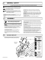
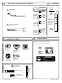
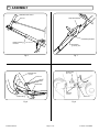
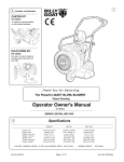
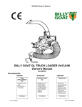
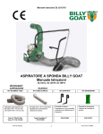
Thank
You
for
S e l e c t i n gg
The Powerful QUIET BLOW® BLOWER
Operator Owner's Manual
2
ACCESSORIES
Push Model
Self Propelled Model
QB1601
QB1601SP
Specifications
3
GUST ADJUSTER KIT
P/N 400685 Increases
blowing distance and
blowing control.
DEFLECTOR REMOTE KIT
P/N 400686 Adds operator
remote control for quickly
changing between side and
forward direction blowing.
(Standard on Self
Propelled models).
Part No. 430149
Engine: HP(kW)
Engine: Type
Engine: Fuel cap.
Engine: Oil Cap.
Weight: Unit
Weight: Shipping
Engine Weight: (kg.)
UNIT SIZE:
QB1601
QB1601SP
16 H.P. (11.93 kW)
B & S VANGUARD - TWIN OHV
9 qt. (8.52 L)
1.75 qt. (1.66 L)
234# (106.1 kg)
268# (121.6 kg)
79# (35.8 kg)
16 H.P. (11.93 kW)
B & S VANGUARD - TWIN OHV
9 qt. (8.52 L)
1.75 qt. (1.66 L)
274# (124.3 kg)
322# (146.1 kg)
79 # (35.8 Kg)
OVERALL LENGTH: 55"(1.4m) OVERALL WIDTH 35" (0.89m)
OVERALL HEIGHT44.5" (1.13m)
Page 1 of 16
Form No. F110802A
IN THE INTEREST OF SAFETY
5
BEFORE STARTING ENGINE, READ AND UNDERSTAND THE “ENTIRE OPERATOR'S MANUAL & ENGINE MANUAL.”
THIS SYMBOL MEANS WARNING OR CAUTION. DEATH, PERSONAL INJURY AND/OR PROPERTY
DAMAGE MAY OCCUR UNLESS INSTRUCTIONS ARE FOLLOWED CAREFULLY.
WARNING: The Engine Exhaust from this product contains chemicals known
to the State of California to cause cancer, birth defects or other reproductive harm.
WARNING: DO NOT
13. DO NOT tamper with governor springs,
governor links or other parts which may
change the governed engine speed.
1. DO NOT run engine in an enclosed area.
Exhaust gases contain carbon monoxide, an
odorless and deadly poison.
14. DO NOT tamper with the engine speed
selected by the engine manufacturer.
2. DO NOT place hands or feet near moving
or rotating parts.
15. DO NOT check for spark with spark
plug or spark plug wire removed. Use an
approved tester.
3. DO NOT store, spill or use gasoline near
an open flame, or devices such as a stove,
furnace, or water heater which use a pilot
light or devices which can create a spark.
16. DO NOT crank engine with spark plug
removed. If engine is flooded, place
throttle in “FAST” position and crank until
engine starts.
4. DO NOT refuel indoors where area is not
well ventilated. Outdoor refueling is
recommended.
17. DO NOT strike flywheel with a hard
object or metal tool as this may cause
flywheel to shatter in operation. Use
proper tools to service engine.
5. DO NOT fill fuel tank while engine is
running. Allow engine to cool for 2 minutes
before refueling. Store fuel in approved
safety containers.
6. DO NOT remove fuel tank cap while
engine is running.
18. DO NOT operate engine without a
muffler. Inspect periodically and replace, if
necessary. If engine is equipped with
muffler deflector, inspect periodically and
replace, if necessary, with correct deflector.
7. DO NOT operate engine when smell of
gasoline is present or other explosive
conditions exist.
19. DO NOT operate engine with an
accumulation of grass, leaves, dirt or other
combustible material in the muffler area.
8. DO NOT operate engine if gasoline is
spilled. Move machine away from the spill
and avoid creating any ignition until the
gasoline has evaporated.
20. DO NOT use this engine on any forest
covered, brush covered, or grass covered
unimproved land unless a spark arrester is
installed on the muffler. The arrester must
be maintained in effective working order by
the operator. In the State of California the
above is required by law (Section 4442 of
the California Public Resources Code).
Other states may have similar laws.
Federal laws apply on federal lands.
9. DO NOT transport unit with fuel in tank.
10. DO NOT smoke when filling fuel tank.
11. DO NOT choke carburetor to stop
engine. Whenever possible, gradually
reduce engine speed before stopping.
21. DO NOT touch hot muffler, cylinder, or
fins because contact may cause burns.
22. DO NOT run engine without air cleaner
or air cleaner cover.
23. DO NOT operate during excessive
vibration!
24. DO NOT leave machine unattended
while in operation.
25. DO NOT park machine on a steep
grade or slope.
WARNING: DO
1. ALWAYS DO remove the wire from the
spark plug when servicing the engine or
equipment TO PREVENT ACCIDENTAL
STARTING.
2. DO keep cylinder fins and governor
parts free of grass and other debris
which can affect engine speed.
3. DO pull starter cord slowly until resistance is felt. Then pull cord rapidly to avoid
kickback and prevent hand or arm injury.
4. DO examine muffler periodically to be
sure it is functioning effectively. A worn or
leaking muffler should be repaired or
replaced as necessary.
5. DO use fresh gasoline. Stale fuel can
gum carburetor and cause leakage.
6. DO check fuel lines and fittings frequently for cracks or leaks. Replace if
necessary
7. Follow engine manufacturer operating
and maintenance instructions.
8. Inspect machine and work area before
starting unit.
12. DO NOT run engine at excessive
SOUND
7
speeds. This may result in injury & /or
damage to unit.
Sound tests conducted were in accordance with 2000/14/EEC
and were performed on 2/13/2002 under the conditions listed:
6
TABLE OF CONTENTS
SAFETY INSTRUCTIONS
PARTS BAG & CONTROLS
LABELS
GENERAL SAFETY
PACKING CHECKLIST
ASSEMBLY
OPERATION
PARTS DRAWING & LIST
MAINTENANCE
TROUBLESHOOTING
WARRANTY PROCEDURE
○
○
○
○
○
○
○
○
○
○
○
○
○
○
○
○
○
○
○
○
○
○
○
○
○
○
○
○
○
○
○
○
○
○
○
○
○
○
○
Part No. 430149
○
○
○
○
○
○
Vibration levels at the operators handles were
measured in the vertical, lateral, and longitudinal
directions using calibrated vibration test equipment.
Tests were performed on 06/24/94 under the conditions
listed:
Sunny
GENERAL CONDITION:
GENERAL CONDITION:
Sunny
○
○
○
Sound level of 99 dBA at operator position
○
○
○
NOTE: Sound power level listed is the highest value for any model in this manual. Please
refer to serial plate on the unit for the sound power level for your model.
VIBRATION
VIBRATION LEVEL 4.0 g
○
○
○
○
○
○
○
○
○
○
2
3, 4
4
3
3
3, 5
6, 7
8 - 12
13 - 15
16
16
○
○
○
○
○
○
○
○
○
○
○
○
○
○
○
○
○
○
○
○
8
43° F (6.1° C)
TEMPERATURE:
○
○
10 MPH (16.1 kmh)
WIND SPEED:
115 dB
North West
WIND DIRECTION:
82.2 %
HUMIDITY:
TEMPERATURE:
WIND SPEED:
WIND DIRECTION:
HUMIDITY:
84° F (28.9° C)
5 MPH (8 kmh)
North East
71 %
○
○
○
BAROMETRIC PRESSURE:
29.72" Hg (754mm Hg)
Page 2 of 16
BAROMETRIC PRESSURE:
29.81" Hg (757mm Hg)
Form No. F110802A
GENERAL SAFETY
9
For your safety and the safety of others, these directions should be followed:
Do not operate this machine without first reading
owner's manual and engine manufacturer's manual.
Use of Ear Protection is recommended while
operating this machine.
Use of Eye and breathing protection is recommended when using this machine, especially in
dry and dusty conditions.
·DO NOT place hands or feet inside air intake opening, near
exhaust outlet or near any moving parts.
·DO NOT start engine without deflector attached to exhaust
outlet.
10
ASSEMBLY
Read all safety and operating instructions
before assembling or starting this unit.
PUT OIL IN ENGINE BEFORE STARTING
Your Billy Goat is shipped from the factory in one carton,
completely assembled except for the upper handle assembly,
side deflector, front deflector, and panel close.
1. Attach upper handle using pre-mounted hardware on
each side (See fig. 6, Page 5).
2. Attach throttle control to upper handle assembly, using
pre-mounted screw and lock nut. Assemble stop switch
bracket, and throttle to handle using same hardware (See fig.
7, Page 5).
11
·DO NOT direct exhaust outlet toward any bystanders.
·DO NOT operate this equipment without first inspecting
work area.
·DO NOT operate this equipment during excessive vibration.
·DO NOT start engine without housing front plate attached.
·DO NOT operate this machine on slopes greater than 20%.
·DO NOT blow any hot or burning debris, or any toxic or
explosive material.
·DO NOT allow children to operate this equipment.
3. Attach throttle cable conduit and stop switch wire to right side of
handle in two (2) places using two cable clamps provided in parts bag
(See fig. 7, Page 5).
4. Self Propelled units only: Remove nuts securing remote exhaust
door control. Use nuts to attach brake and clutch cables as pictured (See
fig. 8, Page 5).
5. Self Propelled units only: Attach ends of clutch cable and brake
cable in holes provided in bail, and secure bail in pivot holes in upper
handle (See fig. 8, Page 5).
6. Self Propelled units only: With remote exhaust door control in
rearmost position and exhaust door in closed position thread remote
deflector rod into ball joints pre-assembled on door control and exhaust
door pivot rod. Adjust to allow necessary range of motion and lcok in
place using jam nuts provided on rod. (See fig. 8 & 9, Page 5)
7. Assemble desired deflectors onto side and front of housing exhaust
outlet using screws provided on unit. (See fig. 9, Page 5)
NOTE: The panel front close can be used to completely block off the
forward exhaust outlet for jobs where only the side exhaust is needed.
PACKING CHECKLIST
Boxing Checklist
These items should be included in your carton. If
any of these parts are missing, contact your dealer.
Check
Handle Upper
Check
Assembly
400984 QB1601
or
430136 QB1601SP
Check
Self Propelled
Unit Shown
Check
Check
Check
Check
Parts Bag
& Literature Assy
Engine
Manual
Per Model
Part No. 430149
Page 3 of 16
Rod Diverter
Remote 400887
SP ONLY
Deflector Low
W.A. 400845
Deflector Front
400680
Panel Front Close
400846
Deflector Side
W.A. 400679
SP ONLY
Check
Parts Bag &
Literature Assy
400983
Check
Briggs & Stratton
Vanguard-Twin
16 HP P/N MS5356
Multi-Lang
Form No. F110802A
PARTS BAG & LITERATURE ASSY P/N 400983
12
13
Clamp Cable 1"
156
900813 Qty. 4
Throttle
Control
Literature Checklist
Owner's
Manual
Check
CONTROLS
Owner's
Manual
430149
Literature
QB1601
Accessories
Check
10
EU Declaration
of Conformity
& EU
Distributor List
14
15
INSTRUCTION LABELS
These labels should be included on your Blower. If any of these labels are damaged, replace them before putting this
equipment into operation. Item and part numbers are given to help in ordering replacement labels..
WARNING
FAST
ENGINE LABELS
Briggs & Stratton Vanguard 16HP
DANGER
400268
EXPLOSIVE FUEL
STOP
SLOW
Stop
position
EU Declaration
of Conformity &
EU Distributor
List
430150
4
Check
Briggs Vanguard
Units have a
choke type
carburetor that is
operated using
choke lever on
side of engine.
Warranty
Card
400972
Warranty
Card
Screw Cap 1/4-20X2-1/4"
8041011 Qty. 1
Start
position
Literature
QB 1601
Accessories
400909
Check
STOP
810736
Label Do Not Fill
While Engine Is Hot
Item 175
Part No.400268
RUN
Label Danger Keep
Hands and Feet Away
Item 172 Part
No.400424
CHOKE
ENGINE MAINTENANCE
830502
Label Oil Chain
Item 100 Part
No. 830502
5
RELEASE TO DISENGAGE CLUTCH
PULL TO ENGAGE CLUTCH
830503
Label Clutch VQ Item
166 Part No. 830503
Label Speed
Control
Item 101
Part No.
830237
4
3
2
1
900327
WARNING
Part No. 430149
OFF
1. CHECK OIL LEVEL
8 HOURS
2. CHECK & CLEAN AIR CLEANER
25 HOURS
3. CHANGE OIL
50 HOURS
4. REPLACE OIL FILTER
100 HOURS
5. CLEAN COOLING FINS
100 HOURS
See Operating and Maintenance Instructions
Label Ear Eye
Breathing Item
No.174 Part No.
890254
OIL CHAIN
EVERY 10 HOURS
ON
RUN
830237
SP Models Only
Label Read
item No.110
Part No. 890301
FUEL SHUTOFF
Label Danger Flying
Material Item 173 Part
No. 810736
890254
All Models
STOP ENGINE AND ALLOW TO
COOL BEFORE REFUELING.
Label Danger Guards
Item 157 Part No. 900327
N
R
Page 4 of 16
Form No. F110802A
10
ASSEMBLY
Exhaust door control
Stop switch bracket
Jam nut
Mounting hardware
Handle mounting
hardware
Stop switch
grounding wire
Fig. 7
Fig. 6
Exhaust door
Exhaust Door
pivot rod
Control
Jam nut
Clutch
Brake
Clutch cable
Deflector
screws
Brake cable
Jam nut
Fig. 8
Part No. 430149
Fig. 9
Page 5 of 16
Form No. F110802A
16
OPERATION
INTENDED USE: This machine is designed for cleaning
outdoor surfaces, where the debris can be effectively
blown into a consolidated area for convenient pickup and
removal.
Do not operate if excessive vibration occurs. If excessive
vibration occurs, shut engine off immediately and check
for damaged or worn impeller, loose impeller bolt, loose
impeller key, loose engine or lodged foreign objects.
Note: See parts list for proper impeller bolt torque specifications. (See trouble shooting section on page 16).
OPTIONAL GUST ADJUSTER KIT increases blowing
distance and blowing control. ( can be purchased
separately, see page 1 for optional accessories).
Deflectors adjusted upward
increases air volume and
blowing distance.
Like all mechanical tools, reasonable care must
be used when operating machine.
Inspect machine work area and machine before operating. Make sure that all operators of this equipment are
trained in general machine use and safety.
PUT OIL IN ENGINE BEFORE STARTING
Fig. 2
16.1
STARTING
Deflectors adjusted
downward increases air
velocity for cleaning crevices
and blowing heavier debris.
ENGINE: See engine manufacturer’s instructions
for type and amount of oil and gasoline used.
Engine must be level when checking and filling oil and
gasoline.
ENGINE SPEED: Controlled by throttle lever on the handle.
Under normal conditions, operate at minimum throttle to
accomplish your current cleaning task.
STOP SWITCH: Located on engine for Push models and on
upper handle for SP models. Switch must be in "ON"
position to start engine.
Fig. 3
FUEL VALVE: Move fuel valve to "ON" position.
Debris in the air stream can be blown farther by adjusting
the deflectors in a consistent up-and-down motion.
CHOKE: Operated with choke lever on side of engine .
THROTTLE: Move remote throttle control to fast position.
Pull starting rope to start engine.
IF YOUR UNIT FAILS TO START:
See Troubleshooting on page 16.
16.2
BLOWING OPERATION
The diverter rod controls the closing (O) and opening ( I ) of the
exhaust outlet. Adjust diverter rod to side discharge for normal
blowing or to forward discharge for blowing along walls, fences or
hard-to-reach areas (see Fig. 1).
Diverter Rod
16.4
HANDLING & TRANSPORTING:
Move diverter rod to closed (O) position. Do not lift by hand. Use
loading ramps or other mechanical assistance. Secure in place during
transport.
16.5
STORAGE
Never store engine indoors or in enclosed poorly ventilated areas with fuel in tank, where fuel fumes may reach an
open flame, spark or pilot light, as on a furnace, water heater,
clothes dryer or other gas appliance.
If engine is to be unused for 30 days or more, prepare as
follows:
Be sure engine is cool. Do not smoke. Remove all
gasoline from carburetor and fuel tank to prevent gum deposits
from forming on these parts and causing possible malfunction
of engine. Drain fuel outdoors, into an approved container,
away from open flame. Run engine until fuel tank is empty and
engine runs out of gasoline.
NOTE: Fuel stabilizer (such as Sta-Bil) is an acceptable alternative in
minimizing the formation of fuel gum deposits during storage. Add
stabilizer to gasoline in fuel tank or storage container. Always follow
mix ratio found on stabilizer container. Run engine at least 10 min.
after adding stabilizer to allow it to reach the carburetor.
Fig. 1
Part No. 430149
Page 6 of 16
Form No. F110802A
OPERATION
16
continued
PROPULSION self propelled only
16.6
PROPULSION: QB1601 self-propelled blowers are equipped
with 5 forward gears, neutral and reverse. (see TABLE 1 below)
With the engine running, and the bail in released position
select desired drive gear.(see Fig. 4) Pull bail against handle
to automatically release brake and engage drive (see Fig. 5).
Smoothly engage the bail.
Use good judgement when operating the self propelled drive.
Fifth gear is a fast walking speed and should be used only for
moving quickly from place-to-place. Using neutral, on level
terrain is advisable when maneuvering in tight areas. This
increases operator control, and can prevent bumping into
nearby objects.
Do not force-shift gears of transmission. Shift gears only when
drive is disengaged. To stop machine, release operator's bail.
To move unit by hand "freewheeling", requires that the gear
shift be in neutral (see Fig. 4), and the operator hold the drive
bail against the handle to disengage the parking brake.
Bail
Released
Automatic
Parking
Brake
Engages
when bail is
released.
MACHINE
PARKED
Fig. 5
When using Reverse - Set Throttle to Idle.
With operator's bail released, move shift lever past neutral
stop, by pulling the shift lever back and moving it to the right,
into "Reverse" gear position. Then smoothly pull operator's
bail against handle. Release bail to stop (see figure 5).
Gear
Shift
Shown In
Neutral
N
Fig. 4
DRIVE GEAR SELECTION @ (3600 RPM)
Self Propelled Only
Position
Rev.
N
1
2
3
4
5
MPH
3.97
0
2.57
3.40
4.46
5.29
KMH
6.39
0
4.14
5.47
7.19
8.52 10.88
6.76
Table 1
Part No. 430149
Page 7 of 16
Form No. F110802A
18
PARTS DRAWING
QB1601, QB1601SP
Part No. 430149
Page 8 of 16
Form No. F110802A
18
PARTS DRAWING
QB1601, QB1601SP
Part No. 430149
Page 9 of 16
Form No. F110802A
Item
No.
PARTS Continued
LIST
Description
QB1601
QTY
QB1601SP
QTY
1
2
3
4
5
6
7
8
9
10
11
12
ENGINE 16 HP VANGUARD
811057
1
811057
1
GRILL SCROLL W. A.
FRAME FRONT WHEEL W.A.
SCREW CAP 1/4-20 x 2-1/4”
NUT LOCK 1/4-20
WASHER FLAT 5/16 SAE
NUT LOCK 5/16-18
CONTROL THROTTLE
400652
400656
*8041011
*8160001
*8172008
*8160002
850270
1
1
1
1
4
16
1
400652
400656
*8041011
*8160001
*8172008
*8160002
850270
1
1
3
6
7
28
1
GUARD MUFFLER
811058
1
811058
1
14
15
16
17
IMPELLER ASSY QB1601
KEY 1/4 SQ X 2.25
WASHER LOCK 3/8 TWISTED TOOTH.
SCREW CAP 3/8-24 X 1 1/4 GR 8 (TORQ 50 ft.lbs.[68 Nm] )
SCREW CAP 3/8-24 x 2 1/4 GR. 8(TORQ. 50 ft.lbs.[68 Nm] )
SCREW CAP 5/16-18 X 1”
WHEEL FRONT
AXLE FRONT
TUBE SPACER QB 1600
CAP - PLUG 1.25 SQ
400720
9201123
400502
400946
*8041028
400295
400730
400733
400640
1
1
1
1
4
1
1
1
2
430107
9201123
400502
810932
*8041028
400295
400730
400733
400640
1
1
1
1
4
1
1
1
2
SCREW CAP 3/8-16 X 1 3/4
SCREW CAP 3/8-16 x 2”
SCREW SHEET METAL 1/4 AB X 3/4
HANDLE LOWER W.A.
SCREW CAP 5/16-18 X 2
DEFECTOR EXHAUST
WASHER WEAR PLATE
ROD DIVERTER QB1600
SPACER
SPRING COMPRESSION
RING GRIP
WASHER FLAT CUT 5/16
SCREW CAP 5/16-18 X 3/4
SCREW MACH #10 - 24 X 5/8 HEX WF
NUT LOCK # 10-24
WASHER FLAT CUT 3/8
WASHER 3/4 SAE
WASHER HUB CAP
WASHER (0.765 X 1.25 OD X 0.06)
PIN COTTER 1/8 X1
CAP HUB
WASHER FENDER
ROD END BALL JOINT 3/8-24
ROD DIVERTER REMOTE
*8041053
*8122082
400735
*8041032
400677
400684
400697
400330
400332
400340
*8171003
*8059135
*8164005
*8171004
*8172015
850237
850238
*8197031
900486
*8172020
-
2
11
2
4
1
1
1
1
1
1
20
6
8
2
6
4
4
4
4
4
-
*8041054
*8122082
400735
*8041032
400677
400684
400697
400340
*8171003
*8041026
*8059135
*8164005
*8171004
*8172015
850237
850238
*8197031
900486
*8172020
400886
400887
2
17
2
2
1
1
1
1
17
4
6
8
1
4
4
4
4
4
4
2
2
NUT LOCK 3/8 - 16
NUT JAM 3/8-24
LEVER FRICTION ASSY
BAR LEVER REMOTE
GRIP HANDLE
NUT 1/4-20 WASHER FACE
SCREW CAP 1/4-20 x 1”
WASHER LOCK 1/4 EXT.
PLATE FRICTION LIFT
NUT JAM 1/4-20
PLATE QUAD LIFT
WASHER 1/4 FLAT CUT
BALL 1/4”
PLATE CLAMP LIFT
WASHER 1/4” BELLVILLE
THROTTLE CONTROL ASSY (Incl. items 5,6,9,156 )
SPACER
BAR MOUNT BRAKE
810135
-
1
-
*8160003
*8149003
400875
400839
850190
900455
*8041006
*8181007
850191
*8150001
850192
*8171002
850194
850193
850207
810135
850198
430112
1
2
1
1
1
1
2
1
1
1
1
2
1
1
2
1
2
1
BAR MOUNT SPRING
DEFLECTOR SIDE WA
SWITCH ENGINE ASSY
WASHER LOCK 5/16 TWISTED TOOTH
430140
800177
1
6
430111
400679
430140
800177
1
1
1
6
18
19
20
21
22
23
24
25
26
27
28
29
30
31
32
33
36
37
38
39
40
41
42
43
44
45
46
47
48
49
50
51
52
53
54
55
56
57
58
59
60
61
62
63
64
65
66
67
68
69
70
98
99
Part No. 430149
19
Page 10 of 16
Form No. F110802A
Item
No.
100
101
102
103
104
105
106
107
108
109
110
111
112
113
114
115
116
117
118
119
120
121
122
123
124
125
126
127
128
129
130
131
132
133
134
135
136
137
138
139
140
141
142
143
144
145
146
147
148
149
150
151
152
153
154
155
156
157
158
159
160
161
162
163
164
165
166
167
168
169
Part No. 430149
19
PARTS Continued
LIST
QB1601
Description
QTY
QB1601SP
QTY
LABEL OIL CHAIN
LABEL SHIFT
WHEEL TIRE ASSY 16”
WHEEL & TIRE ASSY 16” SP
LABEL 1601
WASHER LOCK 1/4 SPLIT
GUARD CLUTCH QB1601SP
GUARD MANIFOLD
SPACER WHEEL
AXLE REAR PUSH
PULLEY IDLER
LABEL READ OWNERS MANUAL
HANDLE UPPER ASSY W/GRIP
IDLER PIVOT WA
PARTS BAG QB 1601
PANEL FRONT CLOSE
DEFLECTOR LOW W.A.
DEFLECTOR FRONT
SPACER ENGINE
SWITCH ROCKER
HARNESS ASSY SV
850147
430114
8177010
811059
800421
400770
890301
400984
400776
400846
400845
400680
500281
890442
2
1
12
1
6
1
1
1
1
1
1
1
1
1
830502
830237
850229
430114
8177010
430145
811059
800421
800260
890301
430136
430157
400846
400845
400680
830112
500281
890442
1
1
2
1
15
1
1
2
1
1
1
1
1
1
1
1
1
1
TRANSMISSION 5 SPD/1 REV. W/BRAKE
PULLEY 7” DIA.
BELT 4L x 34” O.L.
CHAIN #40 x 46 PITCH HEAVY DUTY
DIFFERENTIAL ASSY 28T
BEARING & FLANGE ASSY 0.75”
BELT FINGER WA QB1601SP
PLATE TENSION CHAIN W/INSERT
PLATE MOUNT BEARING
ROD SHIFT WA QB1601SP
-
-
830179
800251
830223
430124
430103
850232
430152
430122
430110
430129
1
1
1
1
1
3
1
2
1
1
PLATE BUSHING SHIFTER
CASTER ASSY 8” PNEU.
CASTER BRACKET WA QB16
PLATE NEUTRAL STOP
CABLE ASSY CLUTCH QB1601SP
CABLE ASSY BRAKE QB1601SP
PLATE GUARD DRIVE
BAIL DRIVE WA QB1601SP
WASHER LOCK 5/16 SPLIT
KEY HI-PRO 3/16 x 3/4
BOLT CARRIAGE 5/16-18 x 1”
SCREW CAP 3/8-16 x 1 1/2
WASHER 3/8 SAE
NUT LOCK 3/8-16 THIN HT.
-
-
430123
400731
430132
430127
430125
430126
430135
430137
*8177011
850234
*8024040
*8041052
*8172009
*8161042
1
1
1
1
1
1
1
1
10
1
6
2
1
1
BOLT SHOULDER 1/2" x 1"
-
-
500114
1
SPRING
SCREW CAP 5/16-24 x 3/4 GR. 5
SCREW CAP 5/16-18 x 2 1/2
NUT JAM 5/16-18
SCREW SELF TAP 5/16 x 3/4
SCREW CAP 5/16-18 X 1 3/4
CLAMP CABLE PLASTIC 1”
LABEL DANGER GUARDS
WASHER 3/4 FLAT CUT
KEY 3/16 SQ. x 2 1/8
SCREW CAP 1/4-20 x 1”
WASHER 3/8 SAE
SPRING TENSION
SCREW CAP 5/16-18 x 3/4”
SCREW CAP 1/4-28 x 1/2 GR. 5
WASHER 1/4 SAE
LABEL CLUTCH
SCREW CAP WASHER FACE SEM 1/4 - 20 X 3/4
HSG ASSY
BASE ENGINE ASSY (PUSH MODEL)
BASE ENGINE ASSY W/LABELS (SP MODEL)
*8041031
900813
900450
400914
430113
-
8
2
2
1
1
-
800242
*8042026
*8041033
*8142002
8123128
*8041031
900813
900327
*8171009
9201087
*8041006
*8172009
400217
*8041026
850408
*8172007
830503
900450
400914
430105
1
2
2
2
4
7
4
1
4
2
6
13
1
7
1
1
1
2
1
1
Page 11 of 16
Form No. F110802A
* Denotes
standard
hardware item
that may be
purchased
locally.
Part No. 430149
19
170
171
172
173
174
175
176
177
178
PARTS Item
Continued
LIST No.
QB1601
Description
QTY
QB1601SP
QTY
SCREW CAP 5/16-18 x 1” GR. 5
400912
4
400912
4
LABEL WARNING OPEI
LABEL DANGER FLYING MATERIAL
LABEL EAR EYE BREATHING
LABEL DO NOT FILL WHEN ENGINE IS HOT
SCREW MACH. #10-24 x 1 1/2
400424
810736
890254
400268
*8059145
1
1
1
1
1
400424
810736
890254
400268
*8059145
1
1
1
1
1
WASHER LOCK 1/4 SPLIT
-
-
*8041029
2
Page 12 of 16
Form No. F110802A
17
MAINTENANCE
Use only a qualified mechanic for
any adjustments, disassembly or
any kind of repair .
WARNING: TO AVOID PERSONAL INJURY, ALWAYS
TURN MACHINE OFF, MAKE SURE ALL MOVING
PARTS COME TO A COMPLETE STOP.
DISCONNECT SPARK PLUG WIRE
BEFORE SERVICING UNIT.
17.1
IMPELLER REMOVAL
continued
12. (Self propelled models only) When impeller is installed,
slide belt into drive pulley.
13. Reattach front intake plate and front wheel bracket
in reverse order of removal.
14. (Self propelled models only) Check operator's bail to
ensure that it operates properly. If not, see drive adjust
ments on page 14). Note: Drive must completely disengage
with bail released and must engage when bail is depressed
within 1.0" (25.4mm) of the operator's handle.
15. (Self propelled models only) Reinstall clutch guard.
16. Reconnect spark plug wire.
ENGINE: See engine manufacturer
operator's instructions.
17.17.1
2
RECONNECT SPARK PLUG WIRE AND
GUARDS BEFORE STARTING ENGINE.
Maintenance Schedule
Follow these hourly
maintenance intervals.
More frequent service is required for extremely dusty conditions.
Maintenance Operation
Every
Use
Every 5 hrs Every 25
or (Daily)
hours
Every 50
hours
Engine (See Engine Manual)
Check for excessive vibration
17.1
IMPELLER REMOVAL
Inspect for loose parts
1. Disconnect spark plug wires.
2. Elevate front of machine using stable support blocks
between housing and ground so that front wheel
is not touching ground.
3. Remove front wheel bracket and front intake plate from the
housing.
4. (Self propelled models only) Remove the clutch guard
from the left side of the unit between housing and engine.
5. Remove impeller bolt and lock washer.
Inspect for damaged parts
6. (Self propelled models only) Slide belt toward engine, out
of belt groove in impeller hub drive pulley.
Grease wheel zerks
7. If impeller slides off freely, proceed to (step 12).(Note: Do not
pull or pry on impeller blades.)(Do not drop impeller).
8. If impeller does not slide off crankshaft, place two crowbars
between impeller and housing on opposite sides. Pry impeller
away from engine until it loosens. Using a penetrating oil can
help loosen a stuck impeller.
9. If the impeller cannot be loosened, obtain a 1” (25.4mm) longer
bolt of the same diameter and thread type as the impeller bolt.
Invert engine and impeller and support engine above ground to
prevent recoil damage. Thread longer bolt by hand into the
crankshaft until bolt bottoms. Using a suitable gear or wheel
puller against the bolt head and the impeller back-plate (near the
blades), remove impeller from shaft.
10. Slide impeller off of crank shaft and remove impeller from
housing.
11. Reinstall new impeller and all applicable spacers, new
impeller bolt and lockwasher in reverse order of removal.
(See the parts drawing on pages 8 and 9 for parts breakdown and parts list on page 10 for proper impeller bolt
torque specifications.)
Part No. 430149
Page 13 of 16
Check tire pressure (p. 14)
Oil control pivot points
Lubricate Drive Chain
Check belt adjustment (p. 14)
Maintenance History
Date of Service
Service Performed
Form No. F110802A
17
MAINTENANCE
continued
Clear intake screens on housing and engine throughout use.
Inspect machine for loose bolts before starting engine.
Lubrication: Using S.A.E. 30 weight oil or
equivalent. See maintenance schedule.
Chain: See SP section below.
Lower Control Ends: Oil moving parts, such as
bail, and deflector door pivots.
Grease: Front wheel, and Caster(SP only).
Tire air pressure: Check at regular intervals & maintain:
Low tire pressure will make unit hard to push and turn.
Front tire at 30 psi. (21.1 kPa).
Rear push 16" tires at 30 psi. (21.1 kPa).
Rear SP 16" tires at 35 psi. (24.6 kPa).
Rear caster tire (SP only) at 30 psi (21.1 kPa)
17.3
DRIVE
Chains and Belts are normal replaceable wear items. A new
chain should not be used on worn sprockets. Sprockets
should be inspected and replaced when worn.
MAINTENANCE- SP MODELS ONLY
Brake Adjustment: As parking brake wears, the brake discs
may eventually require adjustment. To adjust, remove bottom
guard from engine base and tighten brake adjusting nut on
transmission. Adjust cable nut as required. Unit must freewheel in neutral with clutch engaged and brake off.
DO NOT OVER ADJUST.
Chain Adjustment: (See fig. 11)
1. Remove spark plug wire.
2. Remove bottom drive guard.
3. Inspect chain and sprockets for wear, lubrication and
tension. Replace if badly worn or damaged. Skip to CHAIN
REPLACEMENT
4.Check chain tension. There should be no more than 0.25"
total movement when chain is flexed from top to bottom.
5. To increase chain tension, loosen, do not remove, the bolts
that hold the bearings in place on each side and in the center
of the differential.
6. Loosen, do not remove, the Jam nut that locks the bolt into
the chain tensioner on each side of the differential.
7. With the bolts loose, equally tighten the chain tensioner bolt
on both the left and right side of the differential.
8. Adjust in small increments, checking chain alignment,
tension and axle squareness between steps. Roll wheels to
check that there are no excessively tight areas in the chain.
Repeat adjustment steps if necessary. A slightly loose chain is
better than an over tightened one.
9. With chain properly adjusted securely tighten the jam nuts,
and bearing mount bolts.
10. Reinstall drive guard.
11. Reconnect spark plug wire.
Belt Adjustment: As V-belt wears, adjustments may be
required to maintain proper clutch engagement. Adjust by
tightening or by loosening clutch cable adjusting nut as
required, located on operators left near the face of the engine
(See fig. 10). When replacing belt, see BELT REPLACEMENT.
DO NOT OVER ADJUST.
Belt Replacemment:
1. Remove impeller, follow impeller removal instructions on
page 13.
2. Remove six screws securing blower housing.
3. Inspect for worn or damaged pulleys. Replace if necessary.
4. Replace worn belt.
5. Replace housing. Note: Be sure to replace lock clip on
upper bolts in exact manner that it was originally installed.
6. Replace impeller, refer to impeller removal instructions on
page 13.
7. It may be necessary to adjust the belt engagement. See Belt
Adjustment.
Chain Replacement: (See fig. 11)
1. Remove spark plug wire.
2. Remove bottom drive guard.
3. Inspect sprockets for wear. Replace if badly worn or damaged.
4. Release chain tension. See Chain Adjustment.
5. Remove operators right and center axle bearings.
6. Remove old chain by sliding over the axle and out the hole
that the right axle bearing was mounted in.
7. Install new chain in the reverse order of removal.
8. Set chain tension. See Chain Adjustment.
9. Replace bottom drive guard.
10. Replace spark plug wire.
Fig. 10
Chain Lubrication: With machine not running, oil chain using
general purpose S.A.E. 30 weight oil every 25 hours or as
needed. Chain oiling hole is located on operator's left at rear
of engine base. Note: Be sure that entire length of chain is
properly oiled. Oiling only a few positions in the chain rotation
will not properly oil the chain.
Part No. 430149
Page 14 of 16
Form No. F110802A
17.3
DRIVE continued
Chain tensioner bolt
Chain tensioner bolt
Jam nut
Jam nut
Bearing Bolt
Bearing Bolt
Fig. 11
17.5
STOP SWITCH & WIRING DIAGRAM
Spark Plug
Stop Switch (Item 118)
on engine (push) or
on handle (SP)
Spark Plug
Fig. 12
Part No. 430149
Page 15 of 16
Form No. F110802A
20
TROUBLESHOOTING
Before Requesting Service Review These Suggestions
Problem
Possible Cause
Solution
Poor air performance
Air intake or exhaust clogged.
Clear clog.
Machine is difficult to maneuver.
Low tire air pressure.
Inflate front and rear tires to correct pressure.
(See tire pressures on page 14.)
Abnormal vibration
Loose or out of balance impeller or loose
engine.
Check impeller and replace if required. Check
Engine.
Engine will not start
Stop switches off. Choke lever not in on
position. Out of gasoline. Bad or old gasoline.
Spark Plug wire disconnected. Dirty air
cleaner.
Check switches, choke, gasoline and oil. Check
for spark with an approved tester. Clean or
replace air cleaner. Contact qualified service
person.
Engine is locked, will not pull over.
Contact your nearest engine manufacturers
servicing dealer.
Engine problem.
Self Propelled Units Only
No self-propelling
Transmission not in gear. Operator's bail not
engaging belt or out of adjustment. Worn out or
broken chain. Broken or mispositioned belt.
Check transmission gear selection. Check clutch
cable adjustment, belt and chain (See page 14).
Self propelled drive will not release
Sticking belt idler arm. Belt fingers bent or
broken.
Check idler. Idler arm mounting screw may be
too tight or too loose. Check belt guide.
Replace if broken.
Noisy or broken chain
No chain lubrication. Chain out of alignment or
over tensioned.
See Chain Adjustments on page 14.
22.1
21
WARRANTY PROCEDURE
Engine Service and Warranty
22
Contact your nearest engine manufacturer's
authorized servicing dealer.
Record your machine model, serial number
and date-of-purchase and where purchased
Serial Plate
R
Model
115 dB
Unit(Weight)
Unit
lbs.(weight) kg
Part No. 430149
The Machine should be taken to the dealer from whom it was
purchased or to an authorized Billy Goat dealer.
1803 S. Jefferson
P.O. Box 308
Lee's Summit,
MO 64063 / USA
Tel (816) 524-9666
Fax (816) 524-6983
The owner should present the remaining half of the Warranty
Registration Card, or, if this is not available, the invoice or receipt.
CE9
5
The Warranty Claim will be filled in by the authorized Billy Goat
Dealer,who will send it with the faulty part to Billy Goat headquarters.
Serial No.
The Quality / Service department at Billy Goat headquarters will study
the claim and parts and will notify their conclusions.
The decision by the Quality / Service department at Billy Goat
headquarters to approve or reject a Warranty claim is final and
binding.
Engine Power
EnginekW
Power
@
Purchase
Date
Please fill in the WARRANTY CARD and send the upper part to Billy Goat.
The WARRANTY terms are stated on the lower part which remains with the
user. Whenever a Billy Goat Machine is faulty due to a defect in material
and / or workmanship, the owner should make a warranty claim as follows:
rpm
Note: To process a Warranty Claim, it is necessary to quote the Model
& Serial number who are printed on the Billy Goat Serial Plate.
BILLY GOAT INDUSTRIES INC.
P.O. BOX 308, 1803 S JEFFERSON LEE'S SUMMIT, MO. 64082-2312 / USA
PHONE: 816-524-9666 FAX: 816-524-6983 www.billygoat.com
Purchased
from
Page 16 of 16
Form No. F110802A