1
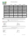
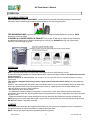
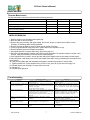
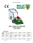
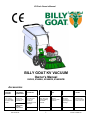
KV Push Owner’s Manual
BILLY GOAT KV VACUUM
Owner's Manual
KV600, KV650H, KV600FB, KV650HFB
Accessories
ON BOARD
VACUUM
HOSE KIT
OPTIONAL
FELT/MESH
DEBRIS BAG
NOZZLE WEAR
GUARD KIT
CASTER KIT
SHREDDER
KIT
KV LINER KIT
PROTECTIVE
COVER
4"(102mm) x
7.5' (2.13m)
For vacuuming
in hard to reach
areas.
For use in
leaves and
grass in dusty
conditions.
For use in
increasing the
life of your
nozzle by
protecting it from
damage
To allow for
easy rolling and
maneuverability
on smooth
surfaces.
Shreds
leaves,
reducing total
volume.
Increases the
life of the
housing by
protecting it from
damage.
Protects the
machine from
the environment
when not in use.
P/N 891127
P/N 891128
P/N 890209
P/N 891134
P/N 891137
P/N 891125
P/N 891126
FELT BAG/
891132
MESH BAG
Part No 891203
1
Form No FF060911D
KV Push Owner’s Manual
CONTENTS
SPECIFICATIONS AND SOUND/ VIBRATION
___
3
INSTRUCTION LABELS
4
PACKING CHECKLIST & ASSEMBLY
5
OPERATION
_6
MAINTENANCE AND TROUBLESHOOTING
7
ILLUSTRATED PARTS & PARTS LISTS
8-9
Go to http://www.billygoat.com for French-Canadian translations of the product manuals.
Visitez http://www.billygoat.com pour la version canadienne-française des manuels de produits
Part No 891203
2
Form No F060911D
KV Push Owner’s Manual
Specifications
KV600
KV650H
KV600FB
Engine: HP
6.0 (4.47 kW)
6.5 (4.85kW)
6.0 (4.47 kW)
6.5 (4.85kW)
Engine: Type
B&S Quantum
HONDA
B&S Quantum
HONDA
Engine: Model
112K020124E1
GSV190AN1L
112K020124E1
GSV190AN1L
Engine: Fuel Capacity
1.5 qt. (1.4 L)
1.6 qt. (1.5 L)
1.5 qt. (1.4 L)
1.6 qt. (1.5 L)
Engine: Oil Capacity
0.63 qt. (0.6 L)
0.58 qt (0.54L)
0.63 qt. (0.6 L)
0.58 qt (0.54L)
Total Unit Weight:
112# (50.8kg)
113# (51.3kg)
112# (50.8kg)
113# (51.3kg)
Overall Length
59” (1.5m)
59” (1.5m)
59” (1.5m)
59” (1.5m)
Overall Width
26. 5” (0.7m)
26.5” (0.7m)
26. 5” (0.7m)
26.5” (0.7m)
Overall Height
42.75” (1.1m)
42.75” (1.1m)
42.75” (1.1m)
42.75” (1.1m)
Max. operating slope
20
0
20
Sound in accordance with
2000/14/EEC standards
108 dBa
Sound at operator’s ear
88 dBa
Vibration at operator
position
0
20
109 dBa
0.5 g (4.95m/s )
0
200
108 dBa
89 dBa
2
KV650HFB
109 dBa
88 dBa
2
0.32 g (3.18m/s )
89 dBa
2
0.5 g (4.95m/s )
0.32 g (3.18m/s2)
SOUND
SOUND LEVEL 97 dB(a) at Operator Position
Sound tests were conducted in accordance with 2000/14/EEC, and were performed on 7-25-07 under the conditions listed below.
Sound power level listed is the highest value for any model covered in this manual. Please refer to serial plate on the unit for the sound
power level for your model.
General Conditions:
Temperature:
Wind Speed:
Wind Direction:
Humidity:
Barometric Pressure:
Sunny
o
o
88 F (31.1 C)
2 mph (3.8 kmh)
South South East
44%
30.07”Hg (764 mm Hg)
VIBRATION DATA
2
VIBRATION LEVEL 0.5g (4.95m/s )
Vibration levels at the operator’s handles were measured in the vertical, lateral and longitudinal directions using calibrated vibration test
equipment. Tests were performed on 12-20-2007 under the conditions listed below.
General Conditions:
Temperature:
Wind Speed:
Wind Direction:
Humidity:
Barometric Pressure:
Part No 891203
Sunny
o
o
47.5 F (8.6 C)
3 mph (4.8kph)
West
87%
29.98 Hg (101.5kpa)
3
Form No FF060911D
KV Push Owner’s Manual
INSTRUCTION LABELS
®
The labels shown below were installed on your BILLY GOAT KV Vacuum. If any labels are damaged or missing, replace them before operating
this equipment. Item numbers from the Illustrated Parts List and part numbers are provided for convenience in ordering replacement labels. The
correct position for each label may be determined by referring to the Figure and Item numbers shown.
LABEL DANGER KEEP HANDS
AND FEET AWAY
ITEM #18 P/N 400424
LABEL READ MANUAL
ITEM #17 P/N 890301
LABEL EAR EYE BREATHING ITEM #20
P/N 890254
LABEL EXPLOSIVE FUEL
ITEM # 16 P/N 400268
DANGER FLYING DEBRIS
ITEM # 19 P/N 810736
LABEL SPARK ARRESTOR
P/N 100252
DEBRIS BAG FOLDING LABEL
LOCATED ON BAG
ENGINE LABELS
HONDA
BRIGGS & STRATTON
Read Owner’s Manual Before Operating.
Lire le manuel d’utilisation avant la mise en route.
Vor Inbetriebnahme Bedienungs - und Wartungsanleitung lesen.
Favor leer las instrucciones de operacion antes de operar el motor.
Consultare il Manuale Uso e Manutenzione prima dell utilizzo.
Las Skotselinstruktionen Innan Start.
ENGINE CONTROLS
Honda Throttle Control
Part No 891203
Briggs Throttle Control
4
Form No F060911D
KV Push Owner’s Manual
PACKING CHECKLIST
Your Billy Goat KV Vacuum is shipped from the factory in one carton, completely assembled except for the
upper handle, debris bag, and bag quick disconnect.
READ all safety instructions before assembling unit.
TAKE CAUTION when removing the unit from the box the Handle Assembly is attached by
cables and folded over
PUT OIL IN ENGINE BEFORE STARTING
PARTS BAG &
LITERATURE ASSY
Warranty card P/N- 400972, Owner’s Manual P/N-891203, General Safety and Warnings Manual- 100294,
Declaration of Conformity P/N-891057, Ty-Wraps 900407 (qty2).
Use Ty-wraps
here
Boxing Parts
Checklist
Debris Bag
P/N-891132
OR
Felt Bag
P/N-891126
Literature Assy
P/N-891123
Connector Quick
Disconnect
P/N-890176
Quick disconnect
Honda 6.5
GSV 190
Briggs & Stratton
6.0 HP Quantum
Fig. 2
ASSEMBLY
1. ASSEMBLE Lift upper handle (item 11), remove items 34, 32, and 33 from lower handle (item 10). Attach and
secure upper handle as shown using same hardware.
2. UNFOLD the debris bag (item 21) and fasten bag neck to bag quick disconnect (item 12). Attach firmly to
housing exhaust (item 1) see fig. 2.
3. ATTACH bag hanger strap to bag supports (item 13), preassembled to upper handle.
4. CONNECT spark plug wire.
Part No 891203
5
Form No FF060911D
KV Push Owner’s Manual
OPERATION
VACUUMING OPERATION
VACUUM NOZZLE HEIGHT ADJUSTMENT: Nozzle height is raised and lowered by rotating the red knob near
the left rear wheel. Nozzle height should be adjusted based on the task being performed.
FOR MAXIMUM PICKUP: Adjust nozzle close to debris, but without blocking airflow into the nozzle. NOTE:
Never bury nozzle into debris.
CLEARING A CLOGGED NOZZLE & EXHAUST: Turn engine off and wait for impeller to stop completely
and disconnect spark plug wire. Wearing durable gloves, remove clog. DANGER the clog may contain sharp
materials. Reconnect spark plug wire.
DEBRIS BAG
Debris bags are normal replaceable wear items.
Note: Frequently empty debris to prevent bag overloading with more weight than you can lift.
An optional felt bag is available for use where debris will be vacuumed in dusty conditions (see Optional Accessories
shown on page 1).
DO NOT place bag on or near hot surface, such as engine. Be sure engine has come to a complete stop before removing or
emptying bag.
This vacuum is designed for picking up trash, organic material and other similar debris (see Safety Warnings
page 4-5).
However, many vacuums are used where dust is mixed with trash. Your unit can intermittently vacuum in dusty areas.
Dust is the greatest cause of lost vacuum performance. However, following these rules will help maintain your
machine's ability to vacuum in dusty conditions:
• Run machine at idle to quarter throttle.
• The debris bag must be cleaned more frequently. A vacuum with a clean, pillow soft bag will have good pickup
performance. One with a dirty, tight bag will have poor pickup performance. If dirty, empty debris and vigorously shake
bag free of dust.
• Pressure-wash debris bag if normal cleaning does not fully clean bag. Bag should be thoroughly dry before use.
NOTE: Having one or more spare debris bags is a good way to reduce down time while dirty bags are being cleaned.
DO NOT leave debris in bag while in storage.
COMPOST
Vacuumed leaves, grass and other organic material from your own yard can be emptied into a pile or composter to
provide enriched soil for later use as fertilizer in gardens and flower beds
NOTE: Allow green chips to dry before spreading around living plants.
Part No 891203
6
Form No F060911D
KV Push Owner’s Manual
MAINTENANCE
PERIODIC MAINTENANCE
Periodic maintenance should be performed at the following intervals:
Maintenance Operation
Every Use (daily)
Every 5 hrs (daily)
Every 25 Hours
z
Inspect for loose, worn or damaged parts.
Clean Debris bag
z
Check bag strap tightness
z
Engine (See Engine Manual)
z
Check for excessive vibration
IMPELLER REMOVAL
1. Wait for engine to cool and disconnect spark plug.
2. Drain fuel and oil from the engine.
3. Remove bag, quick release, and upper handle. Do not kink, stretch, or break control cables, control
housings, or end fittings while removing handles.
4. Remove housing top plate by removing bolts around outside of housing.
5. Leaving engine fastened to top plate, turn it upside down so the impeller is on top.
6. Remove impeller bolt and lock washer and washer.
7. Lift impeller upward. If impeller slides freely, proceed to (step 10).
8. Place two crowbars between impeller and housing on opposite sides. Pry impeller away from engine until it
loosens. Using a penetrating oil can help loosen a stuck impeller.
9. If the impeller does not loosen, use two pry bars and pull the impeller near the hub away from the engine,
this should loosen it and allow you to remove the impeller from shaft. Using a penetrating oil can help loosen a
stuck impeller.
10. Using a new impeller bolt and lockwasher and washer, reinstall new impeller in reverse order.
11. Tighten impeller bolt. Torque impeller bolt to 33-38 Ft. Lbs. (44-51 N.m) (see item 30 on page 15).
12. Reinstall engine onto housing in reverse order of removal.
13. Gas and oil.
14. Reinstall spark plug wire.
Troubleshooting
P ro b le m
A b n o rm a l vib ra t io n .
W ill n o t va c u u m o r h a s p o o r
va c u u m p e rfo rm a n c e
E n g in e w ill n o t s t a rt .
E n g in e is lo c k e d , w ill n o t
p u ll o ve r.
P o s s ib le C a u s e
· L o o s e o r o u t o f b a la n c e im p e lle r o r
lo o s e e n g in e
· d irt y d e b ris b a g . H o s e k it c a p m is s in g .
· C lo g g e d n o z z le o r e x h a u s t . E x c e s s ive
q u a n t it y o f d e b ris .
· Im p ro p e r n o z z le h e ig h t
· S t o p s w it c h o ff. Th ro t t le in o ff p o s it io n .
E n g in e n o t in fu ll c h o k e p o s it io n . O u t o f
g a s o lin e . B a d o r o ld g a s o lin e .
S p a rk p lu g w ire d is c o n n e c t e d . D irt y a ir
c le a n e r
· D e b ris lo c k e d in im p e lle r. E n g in e
p ro b le m .
N o z z le s c ra p e s g ro u n d in
lo w e s t h e ig h t s e t t in g .
N o z z le h e ig h t o u t o f a d ju s t m e n t
T o o m u c h d u s t c o m in g fro m
bag.
· V a c u u m in g ve ry d ry , b rit t le o r s m a ll
d e b ris
Part No 891203
7
S o lu t io n
· C h e c k im p e lle r a n d re p la c e if re q u ire d .
C h e c k e n g in e
· C le a n d e b ris b a g . S h a k e b a g c le a n o r
w a s h . C h e c k fo r h o s e k it c a p . U n c lo g
n o z z le o r e x h a u s t . A llo w a ir t o fe e d w it h
d e b ris
· C h e c k s t o p s w it c h e s , t h ro t t le , c h o k e
p o s it io n a n d g a s o lin e . C o n n e c t s p a rk
p lu g w ire . C le a n o r re p la c e a ir filt e r. O r
c o n t a c t a q u a lifie d s e rvic e p e rs o n .
· S e e p a g e 5 . C o n t a c t a e n g in e s e rvic e
d e a le r fo r e n g in e p ro b le m s
A d ju s t n o z z le h e ig h t (S e e N o z z le
h e ig h t fin e a d ju s t m e n t fo r h a rd s u rfa c e s
on page 5
· S w it c h t o fe lt b a g (s e e p a g e 1
a c c e s s o rie s )
Form No FF060911D
KV Push Owner’s Manual
PARTS DRAWING KV
Part No 891203
8
Form No F060911D
KV Push Owner’s Manual
PARTS LIST
ITEM
PART
1
2
KV650H/KV650HFB
QTY
PART
QTY
MAIN FRAME HOUSING NEW KD
NUMBER
891100-S
1
NUMBER
891100-S
1
NOZZLE ASSEMBLY TKV
891110-S
1
891110-S
1
3
AXLE W A KV MICRO
891138
1
891138
1
4
PLATE TOP ENGINE KV
891007-1-S
1
891007-1-S
1
5
IMPELLER 12.75 W A PUSH VAC
891108-S
1
891108-S
1
6
DOOR EXHAUST ASSY RAW
890148
1
890148
1
7
W ASHER 1/2" SAE Z/P
8172011
4
8172011
4
8
W HEEL ASSY 12" X 2.5" TREAD
900509
4
900509
4
9
ENGINE 6.5 HP HONDA GSV190AN1L
-
-
840069
1
ENGINE 6.0 HP B&S
890622
1
-
-
LOW ER HANDLE KV
891050
1
891050
1
11
HANDLE UPPER KV
891054-S
1
891054-S
1
12
QUICK DISCONNECT
890176
1
890176
1
13
PIN CLEVIS 3/8" x 2.125" LONG
520120
4
520120
4
14
RETAINER
360279
4
360279
4
2
10
Part No 891203
KV600/KV600FB
DESCRIPTION
NO.
15
GRIP HANDLE 1"X 9.5" LG
430342
2
430342
16
LABEL W ARNING FUEL EN/SP
100261
1
-
-
17
LABEL READ
890301
1
890301
1
18
LABEL W ARNING DANGER
400424
2
400424
2
19
LABEL DANGER FLYING DEBRIS
810736
1
810736
1
20
LABEL EAR EYE BREATHING
890254
1
890254
1
21
BAG DEBRIS NO ZIPPER KV
891132
1
891132
1
BAG DEBRIS FELT (FB MODELS)
891126
1
891126
1
23
CABLE THROTTLE ASSY 42" W /CHOKE
891036
1
891027
1
25
BOLT J 3/8-16 X 6"
891071
1
891071
1
26
TY W RAP
900407
3
900407
3
27
W ASHER LOCK 3/8" ST MED
8177012
1
8177012
1
28
KEY 3/16 SQ. X 1.25
9201080
1
9201080
1
29
NUT 1/4-20 ACORN
840071
1
840071
1
30
SCREW CAP 3/8-24X1 LOCKTITE
900154
1
-
-
SCREW CAP 3/8-24X1 1/2" GR. 8
-
-
900344
1
31
SCREW CAP 1/4 - 20 x 5/8 HW H
890359
16
890359
16
32
W ASHER 5/16 FLATW ASHER Z/P
8171003
16
8171003
16
33
SCREW CAP 5/16-18 X 1.75 ZP
8041031
8
8041031
8
34
NUT LOCK 5/16-18
8160002
8
8160002
8
35
SCREW CAP 1/4-20 X 3/4"
8041004
2
8041004
2
36
W ASHER 1/4" SAE ZP
8172007
10
8172007
10
37
NYLON INSERT LOCKNUT, 1/4-20 UNC
8160001
8
8160001
8
38
1/2-13 CAP NUT NP W /PATCH
890530
4
890530
4
39
SCREW CAP 1/4-20x2" HCS ZP
8041010
1
8041010
1
40
SCREW PLASTIC 1/4-10 X 1
891039
8
891039
8
41
SCREW 3/8 x 1 1/2 TAPTITE
890408
3
890408
3
42
NOZZLE TOP HALF KV
891002
1
891002
1
43
NOZZLE BOTTOM HALF KV
891003
1
891003
1
44
PLUG HOUSING KD LB
900146-01
1
900146-01
1
45
SCREW SELF TAPPING 10-24 X 1/2
891043
1
891043
1
46
LABEL KV PUSH
891045
1
891045
1
47
48
49
50
51
52
SCREWCAP 1/4-20 X 1"
KV REINFORCEMENT NOZZLE BRACKET LFT
KV REINFORCEMENT NOZZLE BRACKET RT
SPACER 1.5 OD X .875 ID X .975 THK
WASHER 1.5 OD X .453 ID X .25 THK
W ASHER 1/2" FC
8041006
891062
891064
440153
8171006
6
1
1
1
2
8041006
891062
891064
890616
440153
8171006
6
1
1
1
1
2
53
SPRING COMPRESSION
891072
1
891072
1
54
KNOB 3/8-16 RED
891070
1
891070
1
55
NUT LOCK 3/8-16 THIN
8161042
1
8161042
1
56
LABEL SPARK ARRESTOR EN/SP
-
-
100252
1
57
RING CLASP BAG KV
891155
2
891155
2
90
LABEL MADE IN U.S.A.
520116
1
520116
1
9
Form No FF060911D