1
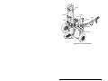
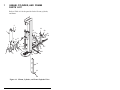
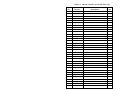
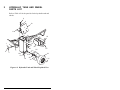
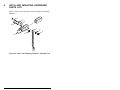
LOG SPLITTER
VERTICAL TYPE
20 TON
Part No. 0108-0104H
Operation and
Maintenance Manual
RNIN
WA
G
lkjh
hkjn
joh i
E USE r uoh ;lm
BEFORthe the jk;lk poj
dop oj yhojklj kpj
dhiug yt bjkj
gyg
[pl\
poio
bj l
hjohoiING USE h nhfgij
DUR bnmlk [p\[\
huig ijkp [p]]
p
I
hgu upo jtbvktv op jop
HFVHG
hioi junoitgb ip jip jk
FRREW Y
ji0 \ guit uyo i ‘
FGJ UFRJ ETRVJH
gutj you jlp
UYO
TUY GYOU TGYYGGHFJH
njt u po[k
BJH HOI GU
IGUGL
huo
HU GOIU YUY FYF
FGYYF HIOI I I
OIPP
HUO G YG UO UO
UGIUG FGYUG
HUO
ING
OW
M T MPH
IMU 35
AX
RE
E FO IBE
HU HUD CTU
N UI INSTRU HOUH
BEFIRE TING F FDYTIU
OPERA HYG I
IP
TH GYVJH GU KKOO
VBH UTR HIO
VHG
TION
FUNC RRUPT
INTE
WA
RN
ED
SPE
M
E
WEDGROL
CONT
RETURN
SPLIT
ING
STA
CLE Y
AR
WAR
NI
STA
Y CL
NG
EAR
LL-204-44
Copyright © Bil-Jax, Inc. 2006
VERTICAL TYPE LOG SPLITTER
This equipment is designed and manufactured in
compliance with the duties, responsibilities, and standards
set forth for manufacturers in the ANSI B71.7 standard in
effect at the time of manufacture.
This equipment will meet or exceed applicable OSHA
codes and ANSI B71.7 standards when used in accordance
with ANSI B71.7 and all other manufacturer’s
recommendations.
It is the responsibility of the user of this equipment to
follow all applicable ANSI, OSHA, Federal, State, and
local codes and regulations that govern the safe operation
of this equipment.
Table of Contents
1
2
3
4
5
6
7
Safety........................................................................................1
1
Introduction..................................................................1
2
Before Operation.........................................................3
3
During Operation .........................................................4
4
Fire Prevention............................................................5
5
Towing Safety..............................................................6
6
Maintenance Safety.....................................................7
7
Hydraulic Safety .........................................................8
8
Damaged Equipment Policy ......................................9
Introduction...........................................................................11
1
General Description ..................................................11
2
Specifications.............................................................12
Operation ...............................................................................13
1
Operation Zone .........................................................13
2
Operator Controls .....................................................14
3
Operating Procedure .................................................16
Maintenance ..........................................................................19
1
Scheduled Service Checks .......................................19
Replacement Decals .............................................................21
Parts List................................................................................25
1
I-Beam, Cylinder, and Frame Parts List ..................26
2
Hydraulic Tank and Wheel Parts List ....................28
3
Hydraulic Pump, Lines, and Valves Parts List .....30
4
Valve Linkage Parts List.........................................32
5
Engine and Mounting Hardware Parts List............34
6
Hitch and Mounting Hardware Parts List ..............36
Warranty ...............................................................................38
i
List of Illustrations
Figure 3-1.
Figure 3-2.
Figure 3-3.
Figure 3-4.
Figure 3-5.
Figure 5-1.
Figure 5-2.
Figure 6-1.
Figure 6-2.
Figure 6-3.
Figure 6-4.
Figure 6-5.
Figure 6-6.
Operation Zone.................................................................13
Operator Controls .............................................................14
Function Interrupt Control Assembly...............................15
Wedge Control Assembly ................................................15
I-Beam Lock Pin ..............................................................16
Replacement Decals .........................................................22
Decal Locations................................................................23
I-Beam, Cylinder, and Frame Exploded View. ................26
Hydraulic Tank and Wheel Exploded View.....................28
Hydraulic Pump, Lines, and Valves Exploded View .......30
Valve Linkage Exploded View ........................................32
Engine and Mounting Hardware Exploded View.............34
Hitch and Mounting Hardware Exploded View ...............36
List of Tables
Table 2-1.
Table 4-1.
Table 4-2.
Table 5-1.
Table 6-1.
Table 6-2.
Table 6-3.
Table 6-4.
Table 6-5.
Table 6-6.
ii
Specifications.....................................................................12
Daily Service Checks.........................................................19
Yearly Service Checks.......................................................20
Replacement Decals...........................................................21
I-Beam, Cylinder, and Frame Parts List ............................27
Hydraulic Tank and Wheel Parts List................................29
Hydraulic Pump, Lines, and Valves Parts List ..................31
Valve Linkage Parts List ...................................................33
Engine and Mounting Hardware Parts List........................35
Hitch and Mounting Hardware Parts List ..........................37
1
Safety
1
INTRODUCTION
Familiarity and proper training are required for the safe
operation of mechanical equipment. Equipment operated
improperly or by untrained personnel can be dangerous. Read
the operating instructions in this manual and become familiar
with the location and proper use of all controls. Inexperienced
operators should receive instruction from someone familiar
with the equipment before being allowed to operate the
machine. The use of intelligence and common sense in the
operation of mechanical equipment is the best practice in any
safety policy. Be professional and always observe the safety
procedures set forth in this manual.
All OSHA, ANSI, state and local codes and regulations
pertaining to this equipment should be obtained, read, and
thoroughly understood before attempting to operate this
equipment. Persons under the influence of drugs, alcohol, or
prescription medication should not be on or near this
equipment. Common sense should be implemented at all times
during the use of this equipment.
This manual covers the AU-5V20H 20 Ton Vertical Log
Splitter manufactured by bil-jax, inc. Additional safety,
operation, and maintenance information for the Honda GX 240
engine is available in the Honda Engines Owner’s Manual
provided with the splitter.
The information contained herein is not to be considered as
legal advice and is intended for informational purposes only.
This information is offered to alert bil-jax customers to
procedures that may be of concern to them.
1
This information is not intended to be all inclusive and is to be
followed in the use of bil-jax equipment only.
For any questions concerning the safe use of this equipment,
call 419.445.9675 before operating.
Safety Notes
This manual contains DANGERS, WARNINGS, CAUTIONS,
and NOTES that must be followed to prevent the possibility of
improper service, damage to the equipment, or personal injury.
DANGER
Dangers warn of equipment operation that could lead to
personal injury or death.
WARNING
Warnings describe conditions or practices that could lead
to personal injury or death.
CAUTION
Cautions provide information important to prevent
errors that could damage machine or components.
NOTE: Notes contain additional information important
to a procedure.
2
2
BEFORE OPERATION
Ensure the following general safety precautions are observed
before operating the splitter.
•
Read and understand this manual completely. For your
own safety and the safety of others, become familiar
with the splitter BEFORE attempting to operate it.
Failure to do so, or any deliberate misuse of the
splitter, may result in serious injury or death.
•
DO NOT allow any untrained adults to operate your
splitter unless they have read and understood this
manual or have been thoroughly instructed in the safe
use of the splitter.
•
DO NOT allow children to operate your splitter.
•
Always inspect your splitter for loose, damaged, or
worn parts before use. DO NOT use if any of these
conditions exist.
•
ONLY one person should load logs and operate the
splitter. If a helper is assisting in log loading, never
activate the controls unless all persons are in the
“operation zone” or clear of the area, a minimum of 10
feet away.
•
DO NOT operate your splitter under the influence of
alcohol, drugs, or other medication.
•
DO NOT operate if you feel tired, ill, dizzy, or
unsteady in any way.
•
DO NOT use your splitter for any other purpose than
splitting wood.
•
DO NOT attempt to move the splitter over hilly or
uneven terrain without a tow vehicle or other help.
•
DO NOT operate the splitter without wearing the
safety goggles provided with the splitter or equivalent
eye protection. Flying wood could cause serious injury
to your eyes.
•
DO NOT operate without wearing safety shoes.
Dropped logs may cause serious injury to feet.
3
3
•
DO NOT operate without wearing protective hearing
devices.
•
NEVER wear loose clothing, jewelry or gloves that
could be caught by moving parts. Keep clothing away
from all moving parts of splitter. Wear proper head
gear to keep loose hair away from moving parts.
DURING OPERATION
Ensure the following general safety precautions are observed
during the operation of the splitter.
4
•
DO NOT attempt to operate the splitter from outside
of the operation zone.
•
DO NOT use the wood splitter with the I-beam in any
position other than vertical. The splitter was designed
to split wood only in the vertical position. Using it in
any other position could cause serious injury to the
user or damage to the splitter.
•
DO NOT operate splitter on slopes, hills, or uneven
terrain. Operate only on level ground. The splitter
could tip over causing serious injury.
•
DO NOT operate splitter on slippery, muddy, or icy
surfaces.
•
ALWAYS block splitter wheels to prevent movement
while in use.
•
ALWAYS keep operation zone and adjacent area clear
for safe and secure footing. Remove split wood
immediately so that you do not stumble over it and
fall.
•
ALWAYS use both hands to operate the Function
Interrupt Valve and Wedge Controls. DO NOT use
any other means to operate the controls.
•
ALWAYS operate your splitter with all safety
equipment in place and all controls properly adjusted.
DO NOT modify or attempt to override or defeat the
safety devices.
4
•
NEVER place hand, foot, or other body part between
log and wedge or log and stripper. When loading
splitter, place hands on the sides of the log.
•
DO NOT attempt to split logs across the grain. Logs
split in this manner may snap away from the wedge
with enough force to cause injury.
•
NEVER attempt to split more than one log at a time.
One may fly out and cause injury.
•
NEVER attempt to load splitter while wedge is in
motion.
•
DO NOT step across the splitter while engine is
running. ALWAYS walk around.
•
NEVER straddle the splitter while in use. Any kind of
slip could cause serious injury.
•
ALWAYS split logs with ends cut square. A log that is
not cut square can be placed with the longest section
against the I-beam and the most square part placed
against the stop.
•
NEVER operate in an enclosed building or where
there is not adequate ventilation.
•
NEVER operate splitter without adequate light.
•
NEVER move the splitter while engine is running.
•
NEVER leave splitter unattended while engine is
running.
FIRE PREVENTION
Ensure the following safety precautions are observed to
prevent fires during the operation of the splitter.
•
The splitter is equipped with an internal combustion
engine and should not be used in or near any
unimproved forest, brush or grass covered areas unless
the exhaust system is equipped with a spark arrester. If
a spark arrester is used, it must be maintained in
effective working order. Check federal, state, and local
code for spark arrester requirements.
5
5
•
ALWAYS have a fire extinguisher available during
splitter operation as a precaution against flying sparks.
•
NEVER operate the splitter near flames or sparks.
Gasoline is extremely flammable.
•
DO NOT smoke while operating or refueling the
splitter. Gas fumes are explosive and extremely
flammable.
•
NEVER refuel a hot or running engine. Allow engine
to cool before refueling.
•
Only refuel splitter outdoors in a clear area free of
fumes and spilled fuel. ALWAYS use an approved
fuel container. ALWAYS replace gas cap securely.
•
If fuel is spilled, move splitter away from the area of
the spill to avoid creating a fire hazard.
•
Fuel should always be stored in an approved, tightly
sealed safety container. ALWAYS store container in a
cool, dry place away from any sources of ignition.
•
ALWAYS drain the fuel tank prior to long term
storage.
TOWING SAFETY
Ensure the following safety precautions are observed during
the towing of the splitter.
6
•
ALWAYS obey all state and local regulations when
towing on public roads and highways.
•
Before towing, ensure the I-beam is stowed in the
down position and secured with the lock pin.
•
Before towing, be certain the splitter is securely
attached to the towing vehicle and the safety chains
are in place. ALWAYS leave slack in chains for
turning allowance.
•
NEVER exceed 35 M.P.H when towing splitter.
Adjust towing speed for terrain and conditions. Use
extra caution when towing over bumpy or rough
terrain including railroad crossings.
6
•
ALWAYS allow for splitter length when turning
corners, parking, crossing intersections, and in all
other driving situations.
•
ALWAYS use caution when backing up splitter. It is
easy to jack-knife the splitter when backing up.
•
NEVER allow anyone to ride on the splitter during
towing.
•
NEVER transport cargo or logs on splitter during
towing.
•
ALWAYS disconnect the splitter from the towing
vehicle before operation.
MAINTENANCE SAFETY
Ensure the following safety precautions are observed when
maintenance is performed on the splitter.
•
Check for worn or damaged parts before each use.
Replace any worn or damaged parts immediately.
NEVER operate with worn or damaged parts.
•
ALWAYS perform maintenance procedures according
to manufacturer’s requirements. NEVER skip or short
change maintenance procedures.
•
ALWAYS keep all mechanisms, nuts, bolts, etc.
properly adjusted and lubricated according to the
manufacturer’s specifications.
•
ALWAYS shut engine off while repairing or adjusting
the splitter except as directed by the manufacturer.
•
Clean debris from splitter and engine regularly. This
must be done with the engine off.
•
NEVER alter the splitter in any way. DO NOT add to
the width or height of the wedge. DO NOT readjust
pressure valves from original manufacturer’s
specifications.
•
NEVER run the engine at excessive speeds. DO NOT
readjust from manufacturer’s preset specifications.
•
NEVER service or repair the splitter without first
removing the spark plug wire.
7
•
7
Use only manufacturer approved parts. Parts must
comply with strict manufacturer specifications. Only
parts purchased from the manufacturer can be
guaranteed to comply with these specifications.
HYDRAULIC SAFETY
Ensure the following safety precautions are observed when any
hydraulic system maintenance is being performed on the
splitter.
WARNING
Hydraulic system under high pressure. Escaping fluid
can have enough force to penetrate skin causing serious
personal injury, even death.
8
•
NEVER check for hydraulic system leaks with hands.
Leaks can be detected by passing cardboard or wood
over the suspected area and checking for discoloration
or fluid on the material used.
•
If injured by escaping fluid, consult a physician
immediately. Serious infection or reaction can develop
if proper medical treatment is not administered
immediately.
•
The hydraulic system of the splitter requires careful
inspection. Be sure to replace frayed, kinked, cracked,
or otherwise damaged hydraulic components to avert
total hydraulic system failure.
•
Before loosening or removing any hydraulic fitting or
line, relieve all pressure by shutting off the engine and
moving the control handle back and forth several
times.
•
NEVER remove the hydraulic reservoir while the
splitter is running. Hot oil under pressure could result
in serious injury.
•
NEVER adjust the pressure relief valve. The pressure
relief valve on the splitter is preset at the factory. Only
a qualified service technician should perform this
adjustment.
8
DAMAGED EQUIPMENT POLICY
Safety Statement
At bil-jax, we are dedicated to the safety of all users of our
products. Therefore, all bil-jax log splitters are designed,
manufactured and tested to comply with current applicable
Federal OSHA and ANSI codes and regulations.
Damage Policy
There may be occasions when a bil-jax log splitter is involved
in an incident that results in structural damage to the splitter.
This can seriously compromise the ability of the splitter to
perform in a safe manner. Therefore, whenever a bil-jax log
splitter is damaged structurally or when there is the possibility
of structural damage (this damage may be internal and is not
always visible to the naked eye), call the bil-jax Service
Department at 419.445.9675. The bil-jax Service Department
will decide if the splitter is required to be returned to our
facility at 125 Taylor Parkway, Archbold, Ohio, for
reconditioning or can be repaired by a qualified repair shop.
Damage Repair Notice
There may be occasions when a bil-jax log splitter is involved
in an accident resulting in non-structural damage. When this
occurs and repairs are made by the owner or area distributor,
please notify bil-jax of these non-maintenance repairs and
request a repair form to be filled out and returned to bil-jax.
9
10
2
Introduction
1
GENERAL DESCRIPTION
The Lumber-Jax 20 Ton Vertical Log Splitter, model AU5V20H manufactured by bil-jax, is designed and built to split
square cut logs up to 24 inches long and up to 8 inches in
diameter.
The splitter is powered by an 8 horsepower Honda GX240
engine. The gas engine drives a 2-stage hydraulic pump that
delivers up to 2500 psi to the hydraulic ram cylinder. During
operation, a steel wedge attached to the cylinder moves
downward splitting the cut log. Cylinder movement is
controlled by two hand controls on the splitter control panel.
The Lumber-Jax is designed to be towed by a standard tow
vehicle and is equipped with a standard 2-inch ball hitch rated
at 3500 pounds. The Lumber-Jax can be towed up to 35 mph
over normal road conditions.
Safety of operation is assured by proper inspection and
maintenance procedures as set forth in this manual. Carefully
read all the safety instructions contained in the Safety section
of this manual before operating the Lumber-Jax log splitter.
11
2
SPECIFICATIONS
Lumber-Jax 20 Ton Vertical Log Splitter
Model Number AU-5V20H
Serial Number __________________
Manufactured by:
bil-jax, inc.
125 Taylor Parkway
Archbold, Ohio 43502
419.445.8915
Table 2-1. Specifications
12
Force
20 tons
Engine
Honda GX240, 8 hp
Pump
2-Stage, 11 gpm (0.7 lps)
Cylinder
4 in. bore x 2 in. rod (10.2 x 5.1 cm)
Stroke
26 in. (66.1 cm)
Hydraulic
System
Pressure
2500 psi maximum
Extend Time
9 seconds
Retract Time
8 seconds
Total Cycle
Time
17 seconds
Frame
6 in. (15.3 cm) I-beam
Wedge Height
8 in. (20.3 cm)
Hitch
2 in. (5.1 cm) 3500 lbs. (1587.6 kg)
Wheel Size
5.3 in. x 12 in. (12.7 cm x 30.5 cm)
Overall Length
108 in. (274.3 cm)
Overall Width
45 in. (114.3 cm)
Overall Height
(Towed)
58 in. (147.3 cm)
Overall Height
(Operational)
77.25 in. (196.2 cm)
Overall Weight
755 lbs (342.5 kg)
3
Operation
OPERATION ZONE
LUMBER
JAX
The Operation Zone is an area located in front of a line
extending out 10 feet from the rear of the control panel and
180° around the front of the unit. Refer to Figure 3-1.
N
O
I
AT
R
PE
O
20 TON
1
WA
ZO
FORE
HUDECTUIBE
UI HU
INSTRU HOUH
BEFIREN ING FDYTIU
IP
HYGF
OPERAT
TH GY GUI KKOO
VBHVJH HIO
VHGUTR
NG
RNI
ihkjnlkjh
USE uohjoh
poj;lm
BEFORE
the ther jk;lk
dop oj yhojklj kpj
dhiug bjkj
gygyt
[pl\
poio
bj l
hjohoi USE nhfgij
DURING
bnmlkh
huig [p]][p\[\
hguijkp p jtbvktv jop
hioiupojunoitgb jip jkop
ji0 \ guit uyoip‘
gutj you jlpi
njt u po[k
huo
TOWIN
UM MPH
XIM 35
MA
G SP
EED
FVHGI
E
N
FRREWH
J ETRYH
FGJ
UYO TGYUFRHFJHVJ
TUY U
GL
GUYGG
BJHGYO
FYFIGU
HOI
HU GOIUI YUY
FGYYF HIOI
HUO G YGI UO UOOIPP
UGIUG FGYUG
HUO
ION
FUNCT RUPT
INTER
E
WEDG OL
CONTR
RETURN
SPLIT
WARN
ING
STAY
CLEAR
WAR
STAY
NING
CLEA
R
N
O
I
AT
R
PE
O
E
N
ZO
Figure 3-1. Operation Zone
DANGER
Always operate splitter while inside the operation zone.
Operating the splitter from outside the operation zone
may cause serious personal injury or death.
Always operate the splitter while inside the operation zone. If
a second individual is assisting in the loading and unloading of
wood, that person must be in the operation zone within
eyesight of the operator before wedge movement can begin.
13
2
OPERATOR CONTROLS
The operator controls are located on the control panel. The
Function Interrupt and the Wedge Control direct the movement
of the wedge during splitter operation. Refer to Figure 3-2.
Before operation of the splitter can begin, hardware for the
Function Interrupt and the Wedge Control must be assembled.
The hardware is located in the tool box attached to the unit. A
pair of needle-nose pliers and a 3/8 inch wrench or adjustable
wrench are needed for control hardware assembly.
CONTROL
PANEL
WEDGE
CONTROL
ING
RN
WA
jnlkjh
E
h ihk
RE US r uohjo j;lm
BEFO the the o jk;lk po
dop oj yh jklj kpj
dhiug t bjkj
gygy
l\
io [p
i po E
bj l
hjoho NG US nhfgij
DURI bnmlkh]][p\[\
huig kp [p
HGI
hguij o p jtbvktv p jop
WHFV
hioiupjunoitgboip jip jko
FRRE ETRY
ji0 \ guit uy i ‘
FGJ FRJ JH
UYO TGYU FJHV
gutj you jlp
u
L
TUY YOU YGGH
[k
njt po
UG
BJHGHOI GUIU
huo
FYFIG
HU F GO I YUY
FGYYO HIOI I UOOIPP
HU G G YG GUO
UGIUO FGYU
HU
FORE
HUDE UIBE
HU RUCT UH
EN UI INST IU HO
BEFIR ATING FDYT
IP
OPERGY HYGF I
TH JH GU O KKOO
VBHV TR HI
GU
VH
TION
FUNCRRUPT
INTE
M
ING
TOW
UM 5 MPH
AXIM 3
SPE
ED
GE
WED ROL
CONT
RN
RETU
SPLIT
WA
R
NIN
G
STA
YC
LE
AR
FUNCTION
INTERRUPT
TOOL BOX
Figure 3-2. Operator Controls
Function Interrupt Control Hardware Assembly
1. In the back of the control panel, connect the link to the
handle with the short clevis pin and cotter pin
provided in the hardware kit. Refer to Figure 3-3.
2. In the front of the control panel, attach the knob with
threaded stud to the handle with the 3/8-16 nut and
3/8-16 locking nut provided in the hardware kit.
Tighten both nuts to secure the knob to the handle.
Press the handle down to test Function Interrupt
control operation.
14
COTTER PIN
SHORT
CLEVIS PIN
FUNCTION
INTERRUPT
VALVE
HANDLE
LINK
KNOB
3/8-16
LOCKING NUT
3/8-16
NUT
Figure 3-3. Function Interrupt Control Assembly
Wedge Control Hardware Assembly
1. Slide the ball handle through the control panel so the
slot in the end of the ball handle rests against a pin in
back of the Wedge Control valve actuator. Refer to
Figure 3-4.
2. Align the front hole on the ball handle with the hole in
the actuator and secure with the long clevis pin and
cotter pin provided in the hardware kit. Move ball
handle up and down to test Wedge Control operation.
WEDGE
CONTROL
VALVE
COTTER
PIN
ACTUATOR
BALL
HANDLE
LONG
CLEVIS
PIN
Figure 3-4. Wedge Control Assembly
15
3
OPERATING PROCEDURE
Perform the following procedures to operate the Lumber-Jax
log splitter.
1. Read and follow all safety precautions contained in
Section 1 of this manual.
2. Position the splitter on a firm and level surface at the
work area. Block the wheels to prevent movement of
the splitter. Unhitch the splitter from the tow vehicle.
3. Ensure that all personal protective equipment such as
goggles, hearing protection, and safety shoes are being
worn.
4. Remove the lock pin from the splitter I-beam hold
down. Refer to Figure 3-5.
I-BEAM
HOLD
DOWN
LOCK PIN
Figure 3-5. I-Beam Lock Pin
WARNING
The splitter is designed to operate with the I-beam in the
vertical position only. Operating the splitter with the
I-beam in any other position may cause serious personal
injury or damage to the splitter.
5. Ensuring the I-beam path is clear, lift the I-beam into
the vertical position. Do not split logs with the I-beam
in any other position.
16
6. Check the engine oil and fuel levels. Refer to the
Honda Engines Owner’s manual in the tool box for
detailed information on the operation and service of
the engine.
7. Start the engine.
WARNING
Load only one log at a time, and with the grain parallel to
the wedge. Loading more than one log and/or against the
grain may cause wood to splinter. Flying debris can cause
serious personal injury.
8. Load only one log at a time with the grain parallel to
the wedge. Do not attempt to split more than one log at
a time. Do not attempt to split a log against the grain.
9. Adjust the stripper bars on each side of the wedge to
the height of the logs to be split. The stripper bars
prevent the wedge from becoming stuck in a partially
split log.
10. Always stay in the operation zone, Figure 3-1, when
operating the splitter controls.
11. Depress the Function Interrupt control with one hand
to activate the Wedge Control.
12. With the other hand, move the Wedge Control lever
down to “Split” a log, then up to “Return” the wedge
to the ready position.
13. When finished splitting all logs, raise the wedge to the
“Return” position and return the stripper bars to their
retracted position.
14. Stop the engine.
15. Move the I-beam into the stowed position and insert
the lock pin.
17
18
4
Maintenance
1
SCHEDULED SERVICE CHECKS
Daily Service Checks
Perform the following service checks daily before each use as
listed in Table 4-1.
Table 4-1. Daily Service Checks
Daily Service Checks
Service engine per instructions in the Honda Engines Owner’s
Manual.
Check ball hitch coupler for damage and missing parts. Ensure ball
hitch operates properly.
Check safety chains and hooks for wear and damage from
dragging. Ensure chains are properly attached to the coupler.
Check side to side movement of the wedge. Movement should be
no more that 1/4 inch. Adjust or replace wear plates as necessary.
Check the hydraulic system for leaks and damaged or worn hoses.
Check hydraulic oil level at the sight gage on the hydraulic tank.
Check all nuts, bolts, screws, and pins for proper tightness and
installation.
Check all safety devices and controls for proper working order.
Check that Operation Manual, Honda Engines Owner’s Manual,
instructional video, and two pairs of goggles are with unit.
Check that all decals are in place and fully readable.
Check tires for proper inflation.
19
Yearly Service Checks
Perform the following yearly service checks as listed in Table
4-2.
Table 4-2. Yearly Service Checks
Yearly Service Checks
Replace hydraulic oil. Clean out any debris in the bottom of the
hydraulic reservoir and sump strainer.
Clean, check, and pack wheel bearings with fresh grease.
20
5
Replacement Decals
Refer to Table 5-1, and Figures 5-1 and 5-2 for descriptions
and locations of decals on the Lumber-Jax log splitter.
Table 5-1. Replacement Decals
Description of Decal
Decal No.
Qty
0202-0340
Function Interrupt
1
0202-0341
Max. Towing Speed 35 mph
2
0202-0342
Lumber-Jax (Transfer type decal)
2
0202-0344
Warning...Stay Clear (Square)
1
0202-0348
20 Ton
1
0202-0380
Warning...Stay Clear While Raising...
3
0202-0381
Warning...Stay Clear
1
0202-0382
Wedge Control
1
0202-0383
Main Warning Decal
1
B06-00-0192
Operation/Service Manual Inside
1
21
MAX. TOWING SPEED
35 MPH
0202-0341
0202-0340
0202-0342
20 TON
0202-0348
0202-0344
STAY
CLEAR
CFU
202-380
0202-0381
0202-0380
0202-0382
B06-00-0192
0202-0383
Figure 5-1. Replacement Decals
22
20 TON
0342
0348
0340
0383
0341
0380
0381
RN
WA
ING
lkjh
hkjn
joh i
E USE r uoh ;lm
BEFORthe the jk;lk poj
dop oj yhojklj kpj
dhiug yt bjkj
gyg
[pl\
poio
bj l
hjohoiING USE h nhfgij
DUR bnmlk [p\[\
huig ijkp [p]]
I
hgu upo p jtbvktv op jop
HFVHG
hioi junoitgb ip jip jk
FRREWJ ETRY
i0 \ t uyo ‘
j
gui i
FGJ UFR HVJH
gutj you jlp
UYO
TUY GYOU TGYYGGHFJ
njt u po[k
BJH HOI GU
IGUGL
huo
HU GOIU YUY FYF
YF
FGY HIOI I
OIPP
HUO G YGI UO UO
UGIUG FGYUG
HUO
E
E FOR
HUD IBE
UI HUINSTRUCTUHOUH
BEFIREN TING F FDYTIU
OPERA HYG I
IP
TH GYVJH GU KKOO
VBH UTR HIO
VHG
TION
FUNC RRUPT
INTE
MA
G
WIN
TO H
UM MP
XIM 35
ED
SPE
E
WEDGROL
CONT
RETURN
SPLIT
0382
WA
RN
ING
STA
CLE Y
AR
WAR
NING
STA
Y CL
EAR
0192
0380
0344
Figure 5-2. Decal Locations
23
24
6
Parts List
25
1
I-BEAM, CYLINDER, AND FRAME
PARTS LIST
Refer to Table 6-1 for the parts list for the I-beam, cylinder,
and frame.
2
3
23
16
18
24
5
10
11
2
12
4
29
30
13
25
17
19
8
6
3
28
15
1
26
16
13
34
33
7 9
20 2
21
27
22
14
31
33
32
Figure 6-1. I-Beam, Cylinder, and Frame Exploded View.
26
Table 6-1. I-Beam, Cylinder, and Frame Parts List
Item
No.
Part No.
Description
Qty
1
0192-0021
Cylinder, Hydraulic 4 in. Bore
1
2
0090-0155
Pin, Cotter, 3/16 x 1-3/4 in.
3
3
0108-0010
Pin, Clevis, 3-1/2 in. (part of 1)
2
4
0108-0165
Wedge
1
5
0090-0991
Screw, Cap, 1/2-13 x 2-3/4 in.
8
6
0108-0197
Plate, Wear, Middle
2
7
0108-0152
Plate, Wear, Bottom
2
8
0090-0159
Nut, Hex, 1/4-20
6
9
0090-0697
Screw, Cap, 1/4-20 x 1 in.
6
10
0090-0212
Washer, Lock, 1/2 in.
8
11
0090-0169
Nut, Hex, 1/2-13
8
12
0068-061
Pin, Snap, 2 in.
3
13
0108-0002
Tube, Stripper
2
14
0108-0136
I-Beam
1
15
0090-0185
Nut, Lock, 5/16-16
2
16
0090-0037
Screw, Cap, 5/16-18 x 2-1/2 in.
1
17
0108-0162
Shock, Tube, Outer
1
18
0192-0060
Shock, Gas, Long
1
19
0108-0158
Shock, Tube, Inner
1
20
0108-0168
Pin, Pivot
1
21
0090-0032
Screw, Cap, 5/16-18 x 1-1/2 in.
1
22
0108-0140
Frame and Axle Weldment
1
23
B30-00-0009
Pad, Boom Support
1
24
0108-0154
Arm Rest, I-Beam
1
25
0090-0162
Nut, Hex, 3/8-16
2
26
0090-0210
Washer, Lock, 3/8 in.
2
27
0090-0053
Screw, Cap, 3/8-16 x 3 in.
2
28
0054-092
Cable, Assembly
1
29
0090-0419
Washer, Flat, 1/4 in.
1
30
0090-0344
Screw, Threadcut, 10-24 x 1/2 in.
1
31
0108-0196
Wear Strip
2
32
0090-0068
Screw, Cap, 1/2-13 x 1-3/4 in
4
33
0090-0574
Washer, Flat, 1/2 in.
8
34
0090-0192
Nut, Lock, 1/2-13
4
27
2
HYDRAULIC TANK AND WHEEL
PARTS LIST
Refer to Table 6-2 for the parts list for the hydraulic tank and
wheels.
8
9
10
11
12
13
4
5
17
6
2
23
21
20
21
25
18
26
7
3
22
24
14
15
16
3
1
21
28
15
27
19
17
18
30
29
31
32
33
34
35
Figure 6-2. Hydraulic Tank and Wheel Exploded View
28
Table 6-2. Hydraulic Tank and Wheel Parts List
Item No.
Part No.
Description
Qty
1
0090-0010
Screw, Cap, 1/4-20 x 1-1/2 in.
1
2
0108-0166
Shock, Tube, Inner
1
3
0090-0183
Nut, Lock, 1/4-20
11
4
0192-0061
Shock, Gas, Short
1
5
0090-0033
Screw, Cap, 5/16 x 1-3/4 in.
1
6
0090-0208
Washer, Lock, 5/16 in.
1
7
0090-0160
Nut, Hex, 5/16-18
1
8
0192-0025
Cap, Filler/Breather
1
9
0192-0058
Fitting, Bushing, Hex Reducer
1
10
0108-0163
Panel, Control, Weldment
1
11
0090-0005
Screw, Cap, 1/4-20 x 3/4 in.
10
12
0108-0149
Reservoir, Hydraulic Oil
1
13
0108-0188
Nut, Sight Gauge
1
14
0090-0049
Screw, Cap, 3/8-16 x 2-1/4 in.
2
15
0090-0422
Washer, Flat, 3/8 in.
4
16
0192-0047
Gauge, Sight
1
17
0090-0210
Washer, Lock, 3/8 in.
4
18
0090-0162
Nut, Hex, 3/8-16
4
19
0090-0042
Screw, Cap, 3/8-16 x 1 in.
2
20
0108-0095
Box, Plastic
1
21
0090-0415
Washer, Flat, #10
6
22
0090-0344
Screw, Threadcut, 10-24 x 1/2 in.
2
23
0054-092
Cable Assembly
2
24
0090-0182
Nut, Lock, #10-24
2
25
0090-236
Screw, Machine, #10, 3/4 in.
2
26
0192-0042
Hub, Group (items 27 thru 33)
2
27
B32-00-0009
Seal, Bearing
2
28
B25-00-0056
Bearing, Wheel
4
29
0192-0103
Hub, 5 Hole (w/Bearings, item 28)
2
30
0090-0882
Washer, Spindle
2
31
0090-0881
Pin, Cotter, 5/32 x 2 in.
2
32
0090-0278
Nut, Castle, 1-14
2
33
B32-00-0011
Cap, Hub
2
34
0192-0035
Assembly, Wheel, Tire
2
35
0090-0624
Nut, Lug
10
29
3
HYDRAULIC PUMP, LINES, AND
VALVES PARTS LIST
Refer to Table 6-3 for the parts list for the hydraulic pump,
lines, and valves.
2
1
3
1
4
1
7
5
6
6
8
9
11
13
12
5
16
14 5
6
5
18
15
10
1
6
17
5
19
5
20
21
Figure 6-3. Hydraulic Pump, Lines, and Valves
Exploded View
30
Table 6-3. Hydraulic Pump, Lines, and Valves Parts List
Item
No.
Part No.
Description
Qty
1
0192-0174
Fitting, 90° Elbow, 1/2 NPTM1/2 Bead
5
2
0192-0064
Hose, Hydraulic, #8 x 59 in.
1
3
0192-0066
Hose, Hydraulic, #8 x 30 in.
1
4
B05-02-0001
Hose, Suction, 3/4 in.
15 in.
5
0108-0092
Clamp, Hose, #20
6
6
0192-0053
Fitting, 90° Elbow, 3/4 NPTM
4
7
0192-0007
Valve, Directional, 3-Position
1
8
0192-0018
Valve, Function Interrupt
1
9
B02-02-0090
Fitting, Hex NIP, 8JICM-8ORN
1
10
0192-0065
Hose, Hydraulic, #8 x 36 in.
1
11
0192-0048
Fitting, Tee 3/4 in.
1
12
B02-02-0007
Fitting, 90° Elbow,
8JICM-8ORM
1
Fitting, 8ORM-8NPTFM
1
13
B02-02-0094
14
0192-0049
Fitting, 90° Elbow, JIC-3/4
1
15
0192-0087
Hose, Hydraulic, #8 x 10 in.
1
16
B05-02-0001
Hose, Suction, 3/4 in.
4 in.
17
0192-0058
Fitting, Bushing, Hex Reducer
1
18
0192-0015
Pump, Hydraulic, 2-Stage
1
19
0192-0092
Hose, Suction, 1 in.
12 in.
20
0192-0059
Fitting, 90° Elbow, Hose Bead
1
21
0082-0756
Strainer, Bushing, 1 x .75 NPT
1
31
4
VALVE LINKAGE PARTS LIST
Refer to Table 6-4 for the parts list for the valve linkage.
1
5
4
2
3
7
8
5
6
5
9
10
11
6
12
15
14
13
Figure 6-4. Valve Linkage Exploded View
32
Table 6-4. Valve Linkage Parts List
Item
No.
Part No.
1
0192-0007
Valve, Directional, 3-Position
(includes items 2-5)
1
2
0192-0051
Handle, Directional Valve
1
3
0090-0717
Knob, Ball, Black, 1 in. Dia.
1
4
0082-0784
Pin, Clevis, Directional Valve
2
5
0090-0143
Pin, Cotter, 1/16 x 3/4 in.
5
6
0108-0074
Pin, Clevis, Interrupt Valve
3
7
0090-0159
Nut, Hex, 1/4-20
1
8
0108-0070
Adapter, Mount, 1/4-20
1
9
0108-0072
Link, Connecting
1
10
0192-0018
Valve, Function Interrupt
1
11
0108-0075
Pin, Clevis, Pilot Stem
1
12
0108-0174
Handle, Function Interrupt Valve
1
13
0090-0188
Nut, Lock, 3/8 in.
1
14
0090-0162
Nut, Hex, 3/8-16
1
15
0090-0734
Knob, Ball, Black, 2-1/2 in.
1
Description
Qty
33
5
ENGINE AND MOUNTING HARDWARE
PARTS LIST
Refer to Table 6-5 for the parts list for the engine and
mounting hardware.
2
1
3
10
4
5
12
8
5
8
9
6
11
13
14
15
6
7
Figure 6-5. Engine and Mounting Hardware
Exploded View
34
Table 6-5. Engine and Mounting Hardware Parts List
Item
No.
Part No.
Description
1
0192-0012
Engine, Honda, GX240
1
2
0090-0035
Screw, Cap, 5/16 x 18 x 3 in.
1
3
0090-0420
Washer, Flat, 5/16 in.
1
4
0090-0046
Screw, Cap, 3/8-16 x 1-3/4 in.
3
5
0090-0421
Washer, Flat, 3/8 in.
7
6
0090-0210
Washer, Lock, 3/8 in.
7
7
0090-0162
Nut, Hex, 3/8-16
3
8
0090-0208
Washer, Lock, 5/16 in.
5
9
0090-0160
Nut, Hex, 5/16-18
1
10
0192-0030
Mount, Pump/Engine
1
11
0090-0043
Screw, Cap, 3/8-16 x 1-1/4 in.
4
12
0192-0026
Coupler, Half, AL-095-1
1
13
0192-0028
Coupler, Spider
1
14
0192-0027
Coupler, Half, AL090-1/2
1
15
0090-0032
Screw, Cap, 5/16-18 x 3/4 in.
4
Qty
35
6
HITCH AND MOUNTING HARDWARE
PARTS LIST
Refer to Table 6-6 for the parts list for the hitch and mounting
hardware.
1
2
3
4
3
2
6
5
6
Figure 6-6. Hitch and Mounting Hardware Exploded View
36
Table 6-6. Hitch and Mounting Hardware Parts List
Item
No.
Part No.
Description
Qty
1
0090-0081
Screw, Cap, 1/2-13 x 5 in.
1
2
0090-0574
Washer, Flat, 1/2 in.
2
3
B03-00-0017
Chain, Safety
2
4
0090-0463
Screw, Cap, 1/2-13 x 4 in.
1
5
0192-0099
Hitch, Ball, 2 in.
1
6
0090-0192
Nut, Lock, 1/2-13
2
37
7
Warranty
bil-jax warrants its log splitters for one year from the date of
delivery against all defects of material and workmanship,
provided the unit is operated and maintained in compliance
with bil-jax operating and maintenance instructions. bil-jax
will, at its option, repair or replace any unit or component part
which fails to function properly in normal use.
This warranty does not apply if the log splitter and/or its
component parts have been altered, changed, or repaired
without the consent of bil-jax or by anyone other than bil-jax
or its factory trained personnel, nor if the lift and/or its
components have been subjected to misuse, negligence,
accident or any conditions deemed other than those considered
as occurring during normal use.
Components not manufactured by bil-jax are covered by their
respective manufacturers’ warranties. A list of those
components and their warranties is available upon written
request to bil-jax.
bil-jax shall not in any event be liable for the cost of any
special, indirect, or consequential damages to any person,
product, or thing. This warranty is in lieu of all other
warranties expressed or implied. We neither assume nor
authorize any representative or other person to assume for us
any other liability in connection with the sale, rental, or use of
this product.
38
39
125 Taylor Parkway
Archbold, OH 43502
Phone (419) 445-8915
(800) 537-0540
Fax
(419) 445-0367
http://www.biljax.com