1
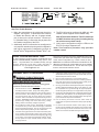
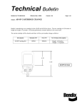
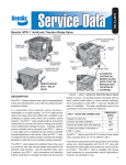
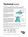
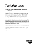
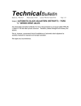
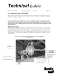
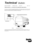
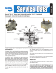
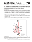
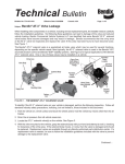
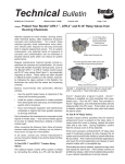
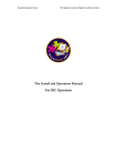
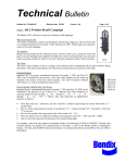
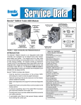
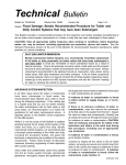
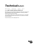
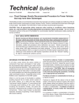
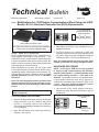
Technical Bulletin Bulletin No: TCH-013-022 Subject: Effective Date: 11/2/2012 Cancels: N/A Page: 1 of 2 Modifications for J1922 Engine Communications When Using non-J1922 Bendix® EC-30™ Electronic Controller Unit (ECU) Replacements For J1939 engine communications, add wires C3 and D3 1 C3 2 3 K J HGF REPLACEMENT ECUs HAVE A LABEL: ECU DOES NOT SUPPORT IN-CAB TRAILER ABS WARNING LAMP (PLC) OR J1922 ENGINE COMMUNICATIONS FIGURE 1 - BENDIX® EC-30™ ANTILOCK ECU Service replacement Bendix® EC-30™ service ECUs no longer support J1922 engine communications. If the original ECU on the vehicle used the J1922 engine link to control the retarder and/or engine traction control, this Bulletin covers the necessary procedures to enable the continued support of these functions. Before beginning service work, ask the engine OEM if the engine Electronic Control Module (ECM) can be upgraded to support J1939 engine communications. For vehicles where this option is available, follow the J1939 Upgrade Procedure, otherwise follow the Hard-Wire Procedure. Note: The J1939 upgrade procedure provides J1939 retarder control and ATC engine and brake control, while the hard-wire procedure only provides retarder control. In all cases follow the General Safety Guidelines shown on page two. D3 ED CBA FIGURE 2 - WIRING DIAGRAM FOR J1939 CONNECTION 3. Reconfigure the ECU by using a diagnostic tool or diagnostic software. 4. The ECU needs to be configured for ABS and Automatic Traction Control (ATC) and retarder control via J1939. Verify the proper configuration using the LEDs on the ECU, or by using a diagnostic tool. Note: The J1939 upgrade procedure provides J1939 retarder control and ATC engine and brake control. HARD-WIRE PROCEDURE NOTE: If the engine ECM can not be upgraded to support J1939 communications, the automatic traction control function — including both the brake and engine-limiting functions — will need to be disabled. The retarder control will now be hard-wired. A good-quality automotive relay will be required to complete this procedure and connect the ECU to the retarder. Step One: Disable Automatic Traction Control for Both the Engine and Brake 1. Gain access to the 18-pin harness connector. Remove the wires that were connected to the D2 and D3 pins. J1939 UPGRADE PROCEDURE 1. Add two 18-gauge twisted pair wires to the harness 30‑pin connector to pin C3 (J1939 H) and pin D3 (J1939 L). C3 and D3 connect to the J1939 bus. Consult the vehicle OEM for assistance in connecting to the J1939 bus. 2. Make the connections to the vehicle per the wiring diagram - See Figure 2. Traction Modulator Source 1 2 3 F ED CBA FIGURE 3 - 18-PIN CONNECTOR D2 D3 Traction Modulator Sink/ Common Bulletin No: TCH-013-022 Effective Date: 11/2/2012 Cancels: N/A Page: 2 of 2 FIGURE 4 - RELAY SWITCH WIRING DIAGRAM Step Two: Enable Retarder 2. Make the connections to the vehicle per the wiring diagram - See Figure 3. To allow the ECU to continue to disable the retarder, add one 18-gauge twisted pair of wires on the 30-pin connector. Connect pin K1 (Retarder Relay). Connect the relay to power and the retarder connection of the ECU. 3. Additionally, the ECU will need to be reconfigured to only expect a retarder relay using a self-configuration that can be performed by a diagnostic tool such as Bendix® ACom® Diagnostics or a Bendix® RDU™ unit. Bendix Technical Assistance Team For direct telephone technical support, call the Bendix Tech Team at 1-800-AIR-BRAKE (1-800-247-2725), option 2, then option 1. Representative are available Monday through Thursday, 8:00 A.M. to 6:00 P.M., Friday, 8:00 A.M. to 5:00 P.M., ET. Or, if you prefer, e-mail the Tech Team at [email protected] GENERAL SAFETY GUIDELINES WARNING! PLEASE READ AND FOLLOW THESE INSTRUCTIONS TO AVOID PERSONAL INJURY OR DEATH: When working on or around a vehicle, the following general precautions should be observed at all times. 1. Park the vehicle on a level surface, apply the parking brakes, and always block the wheels. Always wear safety glasses. 4. The ECU will now be configured for ABS only, with retarder control supplied via the retarder relay. Note: ATC has been disabled. The ATC dash lamp will NOT illuminate at any time (including during the vehicle start-up bulb check). 5. Verify proper configuration using the LEDs on the ECU or by using a diagnostic tool. Note: This hard-wire procedure only provides retarder control. Please have the following information available: Bendix product model number, part number and configuration, vehicle make and model, vehicle configuration (e.g. number of axles, tire size). Reference: The full Service Data sheet for the Bendix® EC-30™ ABS/ATC Controller is SD-13-4815 (BW1794) and is available for download on www.bendix.com. You can also order copies from the online Bendix Literature Center. 5. Following the vehicle manufacturer’s recommended procedures, deactivate the electrical system in a manner that safely removes all electrical power from the vehicle. 6. Never exceed manufacturer’s recommended pressures. 7. Never connect or disconnect a hose or line containing pressure; it may whip. Never remove a component or plug unless you are certain all system pressure has been depleted. 8. Use only genuine Bendix® brand replacement parts, components and kits. Replacement hardware, tubing, hose, fittings, etc. must be of equivalent size, type and strength as original equipment and be designed specifically for such applications and systems. 2. Stop the engine and remove ignition key when working under or around the vehicle. When working in the engine compartment, the engine should be shut off and the ignition key should be removed. Where circumstances require that the engine be in operation, EXTREME CAUTION should be used to prevent personal injury resulting from contact with moving, rotating, leaking, heated or electrically charged components. 9. Components with stripped threads or damaged parts should be replaced rather than repaired. Do not attempt repairs requiring machining or welding unless specifically stated and approved by the vehicle and component manufacturer. 3. Do not attempt to install, remove, disassemble or assemble a component until you have read and thoroughly understand the recommended procedures. Use only the proper tools and observe all precautions pertaining to use of those tools. 11. For vehicles with Automatic Traction Control (ATC), the ATC function must be disabled (ATC indicator lamp should be ON) prior to performing any vehicle maintenance where one or more wheels on a drive axle are lifted off the ground and moving. 10. Prior to returning the vehicle to service, make certain all components and systems are restored to their proper operating condition. 4. If the work is being performed on the vehicle’s air brake system, or any auxiliary pressurized air systems, make certain to drain the air pressure from all reservoirs before beginning ANY work on the vehicle. If the vehicle is equipped with a Bendix® AD‑IS® air dryer system or a dryer reservoir module, be sure to drain the purge reservoir. © 2012 Bendix Commercial Vehicle Systems LLC, a member of the Knorr-Bremse Group. 11/12. All Rights Reserved.