1
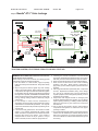
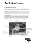
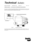
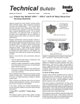
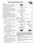
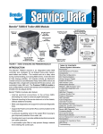
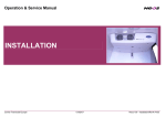
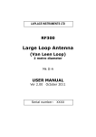
Technical Bulletin
Bulletin No: TCH-013-018
Subject:
Effective Date: 8/24/2009
Cancels: N/A
Page: 1 of 3
Bendix® AT-3™ Valve Leakage
When installing valve components on a vehicle, including service replacement parts, the installer needs to carefully
follow the installation guidelines. Not following these guidelines can lead to damage of the valve and reduced
vehicle braking. Bendix Commercial Vehicle Systems LLC has identified that some Bendix® AT-3™ solenoid
valve bodies have become damaged and may result in leakage. Bendix recommends that the crimp area
of the AT-3™ valve be inspected and replace the valve if this area has been found to have become loose.
See Figure 1.
The Bendix® AT-3™ solenoid valve is a specialized air brake valve which may be used for several functions,
depending on the specific vehicle needs. Most typically, the AT-3™ solenoid valve is used in the Bendix® ATC
automatic traction control and Bendix® ESP® stability systems. See Figure 2 for typical applications of the Bendix
AT-3™ solenoid valve. One or two of these valves may be installed on a vehicle.
Crimp Area
Valve Body
Solenoid Body
Supply Port
Permitted
Clamp
Location
Electrical
Connector
Clamp From
Both Sides of
Mounting Hole
Flange
Permitted
Clamp
Location
Never Clamp
Using Solenoid
Body
Mounting Holes
Delivery
Port
Service /
Exhaust
Port
FIGURE 1 - THE BENDIX® AT-3™ SOLENOID VALVE
To identify if the AT-3™ solenoid valve on your vehicle is damaged, perform the following inspection. Follow all
standard industry safety precautions, including, but not limited to, those included in this document.
1. Park the vehicle on a level surface and block the wheels and/or hold the vehicle by means other than the air
brakes.
2. Drain the air pressure from all vehicle reservoirs.
3. Locate the AT-3™ solenoid valve(s) on the vehicle. See Figure 2.
4. With the valve mounted on the vehicle, grasp the solenoid body with your hand and attempt to rock it, checking
for looseness of the crimp area. If the solenoid body moves, or rocks, then the valve is damaged and should
be replaced. Replacement valves are available through any Bendix authorized parts distribution center. If a
replacement valve is needed, be sure to follow the installation guidelines included with the valve to prevent
damage to the replacement valve.
Continued ...
Bulletin No: TCH-013-018
Subject:
Effective Date: 8/24/2009
Cancels: N/A
Page: 2 of 3
Bendix® AT-3™ Valve Leakage
From Trailer
Control Valve
ABS
Modulator
Quick
Release
Valve
Piloted
Relay Valve
Foot Brake
Valve
Tractor
Protection
Valve
Double
Check
Valve
AT-3™ Solenoid
Valve - Drive Axle
(ATC / ESP)
SER
DEL
Pressure
Reducing
Valve
Trailer Modulator Valve
ABS
Modulator
SUP
Relay
Valve
SUP
DEL
EXH
AT-3™ Solenoid Valve
(HSA-Hill Start Aid)
ABS
Modulator
SER
DEL
SUP
ABS
Modulator
AT-3™
Solenoid
Valve - Steer
Axle (ESP)
Supply
Secondary
Primary
PRIMARY
FIGURE 2 - EXAMPLE APPLICATIONS OF BENDIX® AT-3™ SOLENOID VALVE; 6X4 TRACTOR WITH
TRACTION CONTROL, ELECTRONIC STABILITY AND HILL START AID
WARNING! Please READ and follow these instructions to
avoid personal injury or death:
When working on or around a vehicle, the following general
precautions should be observed at all times.
1. Park the vehicle on a level surface, apply the parking
brakes, and always block the wheels. Always wear safety
glasses.
2. Stop the engine and remove ignition key when working
under or around the vehicle. When working in the engine
compartment, the engine should be shut off and the ignition
key should be removed. Where circumstances require that
the engine be in operation, EXTREME CAUTION should be
used to prevent personal injury resulting from contact with
moving, rotating, leaking, heated or electrically charged
components.
3. Do not attempt to install, remove, disassemble or
assemble a component until you have read and thoroughly
understand the recommended procedures. Use only the
proper tools and observe all precautions pertaining to use
of those tools.
4. If the work is being performed on the vehicle’s air brake
system, or any auxiliary pressurized air systems, make
certain to drain the air pressure from all reservoirs before
beginning ANY work on the vehicle. If the vehicle is
equipped with an AD-IS® air dryer system or a dryer
reservoir module, be sure to drain the purge reservoir.
5. Following the vehicle manufacturer’s recommended
procedures, deactivate the electrical system in a manner
that safely removes all electrical power from the vehicle.
6. Never exceed manufacturer’s recommended pressures.
7. Never connect or disconnect a hose or line containing
pressure; it may whip. Never remove a component or
plug unless you are certain all system pressure has been
depleted.
8. Use only genuine Bendix® replacement parts, components
and kits. Replacement hardware, tubing, hose, fittings,
etc. must be of equivalent size, type and strength as
original equipment and be designed specifically for such
applications and systems.
9. Components with stripped threads or damaged parts
should be replaced rather than repaired. Do not attempt
repairs requiring machining or welding unless specifically
stated and approved by the vehicle and component
manufacturer.
10. Prior to returning the vehicle to service, make certain all
components and systems are restored to their proper
operating condition.
11. For vehicles with Automatic Traction Control (ATC), the ATC
function must be disabled (ATC indicator lamp should be
ON) prior to performing any vehicle maintenance where
one or more wheels on a drive axle are lifted off the ground
and moving.
Bulletin No: TCH-013-018
Subject:
Effective Date: 8/24/2009
Cancels: N/A
Page: 3 of 3
Bendix® AT-3™ Valve Leakage
The following is for reference only and should not
be used in lieu of the instructions provided with the
service replacement valve.
ASSEMBLY
Note: All torques specified in this document are
assembly torques and can be expected to fall off slightly
after assembly. Do not re-torque after initial assembly
torques fall. For assembly, use hand tools or torque
limited drivers only. Do not use impact driver to install
any fittings. Use a professional grade thread sealant
on all air hose connections to this valve.
INSTALLATION
Bendix approves two methods of installation:
(a) either install the valve onto the vehicle with OEM
approved mounting bolts, and then attach the
fittings, or,
(b) bench installation of the fittings, using only the
clamp location shown in Figure 1, before installing
the valve on the vehicle.
1. Clean and inspect all air lines and electrical
harnesses for damage and replace as necessary.
Select one of the two fitting installation methods, either
install the valve onto the vehicle first, or clamp, as shown
in Figure 1, using a bench vise for steps 2 and 3.
2. With thread sealant applied, connect the (1/4-18
NPT) supply and delivery air lines to the valve to
an initial torque of 15 ± 3 ft. lbs. The fittings may be
oriented clockwise, no more than one (1) additional
turn to its final position.
3. For vehicles where the service / exhaust port is
used, apply thread sealant to the hose connector
and tighten to 18 ft. lbs. (25 N•m).
Where the fittings were installed using a bench vise,
now install the valve onto the vehicle.
4. In cases where the service / exhaust port is open to
the atmosphere, remember to install the valve with
this port oriented downwards (within 30 degrees of
vertical). Where used, re-install the snorkel tube
retained during disassembly. Be sure to check that
the snorkel tube has a constant downward slope.
Consider installing a snorkel tube for open service
ports in locations where road spray could enter the
valve.
5. Reconnect the wire harness to the solenoid using
the identification made during the REMOVAL step.
Be sure to check that the harness has sufficient tiewraps, etc. to prevent any damage during vehicle
operation.
6. Test valve as outlined in Operational and Leakage
Tests.
OPERATIONAL AND LEAKAGE TESTS
1. Chock the wheels, fully charge the air brake system
and apply the brakes.
2. Coat the valve with a soap solution; leakage of a
one-inch bubble in 3 seconds is permitted. Where
the service / exhaust port is open to the atmosphere,
do not spray the soap solution directly into this port,
or snorkel tube, where installed.
OPERATION TEST
Since this valve is used for different functions depending
on the vehicle, consult the vehicle Operator’s Manual
for further information. For vehicles where this valve is
being used for ATC functions, you may also refer to the
Antilock Traction Controller’s Service Data sheet (visit
www.bendix.com) for operational test(s) for traction
functionality. In addition, for certain vehicle air brake
systems, a PC with the Bendix® ACom™ Diagnostics
software (BW2329) may be used to test the valve.
BENDIX TECHNICAL ASSISTANCE TEAM
For direct telephone technical support, call the Bendix Tech Team at: 1-800-AIR-BRAKE
(1-800-247-2725), option 2 Monday through Friday, 8:00 A.M. to 6:00 P.M. EST, and follow
the instructions in the recorded message, or you may e-mail: [email protected].
©2009 Bendix Commercial Vehicle Systems LLC 8/09. All Rights Reserved. Printed in U.S.A.